Table of Contents
Advertisement
Quick Links
Advertisement
Table of Contents

Related Manuals for Mini?Cam Proteus Lite

Summary of Contents for Mini?Cam Proteus Lite
- Page 1 Original Instruction Manual Version C...
- Page 2 Mini-Cam Proteus Lite Version C...
- Page 3 Mini-Cam. Mini-Cam Limited Unit 4 Yew Tree Way, Golborne, Warrington, Cheshire WA3 3JD. Phone: +44 (0) 1942 444555 Company Registered in England & Wales • Company Registration No: 3728693 Version C Mini-Cam Proteus Lite...
-
Page 4: Table Of Contents
Connection of Cabling between Control Unit and Cable Reel .....25 Connection of Cabling between Cable Reel and Crawler ......26 Disconnecting Cabling between Cable Reel and Crawler ......27 Manual Elevator ..................28 Connection of Camera to Crawler ..............29 Mini-Cam Proteus Lite Version C... - Page 5 Connecting to your PC ..............52 File Sharing ..................53 Wincan Web ..................53 Share Status ..................54 Information and Care .................55 Cleaning ...................55 Maintenance ..................55 Technical Details - CCU208 .................56 RMPL250 - Cable Reel Connections and Descriptions ..............58 Cable Layering Arm ..................59 Version C Mini-Cam Proteus Lite...
- Page 6 Connections and Descriptions ..............73 Technical Details ALB300 ................73 Information and Care of Camera Modules ..........74 Pressurisation ...................74 Cleaning ...................74 Maintenance ..................74 Reporting Software Principle ......................76 Basic Usage ....................77 Quick User Guide Create a New Project ..................78 Mini-Cam Proteus Lite Version C...
- Page 7 Reviewing the Survey ................101 Viewing the Observations ...............101 Editing an Existing Observation ..............102 Creating a New Observation ..............103 Creating Reports ..................104 Creating Reports for the Whole Project ...........104 Creating Reports for a Selected Section ..........106 Version C Mini-Cam Proteus Lite...
- Page 8 WEEE Statement Information on Disposal for Business Users ..........109 In the European Union ................109 For Spain ....................109 Countries outside the EU ................109 Batteries Product Serial Numbers Useful Information Notes Mini-Cam Proteus Lite Version C...
-
Page 9: Warranty
Mini-Cam Limited is not responsible for direct, special, incidental or consequential damages resulting from any breach of warranty including lost profits, downtime, goodwill, damage to or replacement of equipment and/or property. Version C Mini-Cam Proteus Lite... -
Page 10: Introduction
Lite is the ideal starter kit for a one-man operation, integration into a small inspection van, or a low-cost option for larger companies to use for off-road, remote locations. Proteus Lite provides all the resources required to undertake efficient, easy to perform inspections, and with ProPIPE+ and WinCan Embedded software as standard, you can deliver accurate, detailed reports, instantly on-site. -
Page 11: Text Conventions
When describing control unit operation, sequential menu selections are described in the following format: Setup > Camera > Enable Backeye Camera > OK This example describes pressing the Setup key and selecting the Camera and Backeye options, and finally pressing the OK key. Version C Mini-Cam Proteus Lite... -
Page 12: Product Description
The system uses a control unit with twin joysticks, keyboard, and reporting software developed in-house by Mini-Cam. Built using high quality materials and state of the art technology the Proteus Lite inspection system is a robust and powerful tool for use in harsh ™ environments. Mini-Cam Proteus Lite Version C... -
Page 13: Ec Declaration Of Conformity
Safety Directive. The following are the stipulated operating and environmental conditions for said compliance: Residential, business, commercial, small-company and light industrial environments. This declaration is based on test report(s) of the relevant EMC testing laboratory. Version C Mini-Cam Proteus Lite... -
Page 14: System Overview
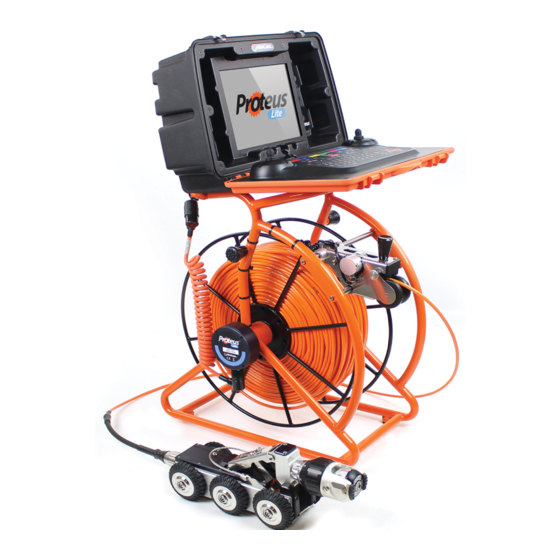
Lite inspection system consists of the following main components: ™ • Control Unit ( A ) • Cable Reel ( B ) • Crawler ( C ) • Camera ( D ) A typical configuration is shown in this illustration: *not to scale Mini-Cam Proteus Lite Version C... -
Page 15: Warnings, Safety Measures And Care
• This hazardous voltage may be exposed if the control unit, cable reel or crawler is opened while the system is operational. Therefore the modules of the system should only be opened by a Mini-Cam Service Centre . Version C Mini-Cam Proteus Lite... - Page 16 DANGER! Risk of deadly injuries from electrical current! Only the power supply supplied as part of the Proteus inspection ™ system can be used and should NOT be replaced by any other. Mini-Cam Proteus Lite Version C...
-
Page 17: Before First Use
For inspections in wastewater and freshwater use a separate inspection system for each. Bacteria can lead to an infection. All individuals employed for the work must be advised of the hazards and must be instructed in the required safety measures. Version C Mini-Cam Proteus Lite... - Page 18 Mini-Cam Ltd to obtain information on system components destined for this purpose. CAUTION! Suffocation hazard! Before and while lowering the crawler into the pipe system it is necessary to perform a safety test with a certified gas detector. Mini-Cam Proteus Lite Version C...
-
Page 19: Safety Measures
• Seek instruction for the handling of hazardous substances. • Adhere to the safety information described in this user manual. • The operator must wear safety equipment that is appropriate to the survey being performed (such as goggles, gloves, safety shoes, etc). Version C Mini-Cam Proteus Lite... - Page 20 • Only use the inspection system for work that is appropriate to the specifications • Observe the operational requirements for this inspection system as described in this user manual. • Keep the system clean. Observe the individual cleaning instructions for this purpose. Mini-Cam Proteus Lite Version C...
-
Page 21: Maintenance
The specific maintenance work steps will also be explained. NOTE! The operator of the system is responsible for the proper disposal! See information on page 109 on the return of equipment at the end of the useful life. Version C Mini-Cam Proteus Lite... -
Page 22: Cleaning
• Check O-rings for damage and replace if necessary and grease regularly with O-ring lubricant. • Clean the cable reel and control unit with a damp cloth. • Only clean the camera and light lenses with a specific lens cleaning cloth to prevent scratches. Mini-Cam Proteus Lite Version C... -
Page 23: Checking Plug And Socket Connections
Clean dirt and moisture from the pins and connectors using an electronic contact cleaner aerosol. NOTE! • Disconnect the power supply from the system. • Check the O-rings for damage and replace if necessary. • Grease the O-rings if necessary using O-ring lubricant. Version C Mini-Cam Proteus Lite... -
Page 24: Connecting The Proteus™ Lite System
NOTE! The fitting and removal of wheels is exactly the same procedure for all Proteus™ crawlers. The illustration above shows the CPL150. Mini-Cam Proteus Lite Version C... -
Page 25: Connection Of Cabling Between Control Unit And Cable Reel
2 Plug the female plug ( D ) of the link cable into the side of the cable reel ( E ). Notice the orientation of the plugs. Secure in place with locking ring ( F ). NOTE! To remove the connectors turn the retaining ring anti-clockwise. Version C Mini-Cam Proteus Lite... -
Page 26: Connection Of Cabling Between Cable Reel And Crawler
2 Turn the retaining ring ( B ) clockwise, as viewed from the cable, to lock the cable end connector into the socket ( D ). The retaining ring is not able to unscrew itself during use if cleaned and maintained correctly. Mini-Cam Proteus Lite Version C... -
Page 27: Disconnecting Cabling Between Cable Reel And Crawler
1 To unscrew the retaining ring you must pull the ring away from the crawler body before rotating anti-clockwise. NOTE! Always fit the protective caps when the crawler, camera or auxiliary module are not in use to protect from damage, ingress of dirt and moisture. Version C Mini-Cam Proteus Lite... -
Page 28: Manual Elevator
Use a 4mm Allen Key ( A ) to loosen the two hex bolts ( B ). Grip the elevator arm ( C ) firmly and pull upwards to the required height position. Secure the elevator using the 4mm Allen Key to tighten the hex bolts. Mini-Cam Proteus Lite Version C... -
Page 29: Connection Of Camera To Crawler
5 Turn the grub screw ( D ) to lock the retaining ring in position using 3mm Allen Key. DO NOT OVER TIGHTEN! 6 Removal is the opposite of fitting. NOTE! Grub screw has a mushroom head and cannot be fully removed. DO NOT OVER TIGHTEN! Version C Mini-Cam Proteus Lite... - Page 30 Proteus CPL150 Crawler with CAM026 Pan & Rotate Camera attached (see page 29 for instructions). Protective NOTE! Always fit the protective caps when the camera is not in use to protect from damage, ingress of dirt and moisture. Mini-Cam Proteus Lite Version C...
-
Page 31: Connection Of Auxiliary Module To Crawler
( B ) onto the camera housing. NOTE! Always fit the protective caps when the crawler, camera or auxiliary module are not in use to protect from ingress of dirt and moisture. Version C Mini-Cam Proteus Lite... -
Page 32: Pressurising The Proteus™ Lite Inspection System
The control unit displays the internal pressure reading for each of the pressurised modules when the system power is ON. CAUTION! Use a pressure reducing valve when pressuring a module. Never attempt to connect the gas bottle directly to a system module. Mini-Cam Proteus Lite Version C... -
Page 33: Instructions For Pressurising The Cpl150 Crawler
CCU section of this manual on specific instructions on how to access the pressure gauges. 5 Remove the pressure valve connection adaptor ( B) . 6 Refit the pressure valve protection cap ( A) . Image shows an example of the control unit crawler pressure gauge: Version C Mini-Cam Proteus Lite... -
Page 34: Testing The System
Press the Backeye button. Camera view will change to rear view. ii Turn the light intensity up and down. iii Press the Backeye button again. Camera view will revert to forward view. Mini-Cam Proteus Lite Version C... -
Page 35: Lowering The Crawler Into The Manhole
To retrieve the crawler from the chamber use the lowering rope ( A ) and hook ( B ) to attach to the crawler lowering handle ( C ). Lift the crawler out of the chamber, balancing the crawler by using the crawler cable ( D ). Version C Mini-Cam Proteus Lite... -
Page 36: Ccu208 - Control Unit
USB or SD card. The control unit can generate on screen text that is overlaid onto the recorded video in various colours and positions, allowing easy customisation. Mini-Cam Proteus Lite Version C... -
Page 37: Ccu Overview
9 Media function keys 3 Right joystick for camera control 10 Camera function keys 4 Speaker 11 Snapshot key 5 ON/OFF button 12 Recording and playback keys 6 ALL STOP button 13 Keyboard 7 Crawler function keys Version C Mini-Cam Proteus Lite... -
Page 38: On/Off Button
• The ALL STOP button can be used in case of emergency, to stop the crawler and disable the power NOTE! The ALL STOP button must be pressed to disable the power to the crawler before disconnecting any part of the system. Mini-Cam Proteus Lite Version C... -
Page 39: Power On Sequence
3 The control unit will now power down. 4 The system can now be disconnected. NOTE! Always fit the protective caps when the crawler, camera or auxiliary module is not in use to protect from ingress of dirt and moisture. Version C Mini-Cam Proteus Lite... -
Page 40: Crawler Function Keys
6 Sonde a Enable or disable sonde function (if purchased-optional). b Choose transmission frequency. NOTE! Moving the crawler joystick during Cruise mode will cancel the cruise control function. The operator will now have manual control. Mini-Cam Proteus Lite Version C... -
Page 41: Survey Function Keys
Survey function keys 1 Meterage Change meterage manually. Change position of meterage on the screen 2 Text Change text colour 3 S urvey Folder Start ProPIPE + or WinCan survey. Version C Mini-Cam Proteus Lite... - Page 42 Media function keys 1 Copy a Copy files from one media source to another 2 Storage media a Choose storage media - Internal/USB/SD card 3 Gallery a Browse surveys, videos and pictures Mini-Cam Proteus Lite Version C...
-
Page 43: Camera Function Keys
Camera function keys 1 Digital Zoom 2 Camera Illumination 3 Focus- 4 Focus+ 5 Camera Home a Automatically move camera to home position (CAM026 only) 6 Camera Settings Version C Mini-Cam Proteus Lite... -
Page 44: Snapshot Key
Press this key to take a JPG image of the live video or video during playback Recording and Playback keys These keys control the recording and playback of video files QWERTY keys These keys allow the user to enter text for on screen text or survey comments Mini-Cam Proteus Lite Version C... -
Page 45: Pressurising Operation Mode
To access the Pressurisation Operation Mode press the HELP key and select the module you want to pressurise. Image shows an example screen shot for the camera Version C Mini-Cam Proteus Lite... -
Page 46: Connections And Descriptions
3 External media protection cover a To protect the connectors from dirt and moisture. NOTE! Always fit the external media protection cover (3) into position to protect from ingress of dirt and moisture. Mini-Cam Proteus Lite Version C... -
Page 47: Rear View
3 Expansion Slot Protection Cover a To protect the expansion slot from ingress of dirt and moisture. NOTE! Always fit the expansion slot protection cover ( 3 ) into position to protect from ingress of dirt and moisture. Version C Mini-Cam Proteus Lite... -
Page 48: Wifi Module
It improves the speed of reporting without the need of exchanging SD cards or USB sticks. Mini-Cam Proteus Lite Version C... -
Page 49: Using Wifi
This feature allows the user to connect the CCU to WiFi. 1 Select WiFi from the Setup and Configuration drop-down menu. 2 A menu will be displayed giving options to connect to WiFi. 3 Select Stored F3 (Yellow Key) to view stored network URLs (addresses). Version C Mini-Cam Proteus Lite... - Page 50 4 Select Find WiFi... F1 (Red Key) to search for available networks. 5 Select the required network from the menu. 6 Select Connect F1 (Red Key) to connect to the selected network (you will have to type a WiFi password in if required). Mini-Cam Proteus Lite Version C...
- Page 51 8 The main display screen shows the WiFi status icon at the bottom right-hand side of the sidebar. WiFi NOT CONNECTED Red cross indicates no signal WiFi CONNECTED Vertical blue coloured bars indicate signal strength Version C Mini-Cam Proteus Lite...
-
Page 52: Connecting To Your Pc
ProPIPE Reports, or alternatively you can save them onto your PC. NOTE: If the CCU is not displayed after the first search, try searching again by hitting the Refresh button on the menu bar Mini-Cam Proteus Lite Version C... -
Page 53: File Sharing
5 Enter Login and Password, then press OK . The WinCanWeb will start the sending process. A message will be displayed with the sending progress, which will display Sent when the upload has finished. Version C Mini-Cam Proteus Lite... -
Page 54: Share Status
NOTE: To successfully share files, the CCU needs to remain on and connected to the internet until the sharing has finished. Mini-Cam Proteus Lite Version C... -
Page 55: Information And Care
It must be noted that although the cable reel and crawler are for use in wet environments the control unit is for indoor use but may also be used outdoor in very light rain. The external PSU is for indoor use only as marked on its label. Version C Mini-Cam Proteus Lite... -
Page 56: Technical Details - Ccu208
Product ID: CCU208 Dimensions: 430 x 280 x 150mm (L x W x D) Power Consumption: 30W (standalone) Weight: 5.5Kg (12.12lb) Temperature Range: -10°C ~ +40° C Environmental Protection: IP54 Charging Time 11 Hours (Maximum) Mini-Cam Proteus Lite Version C... -
Page 57: Rmpl250 - Cable Reel
• Unique cow-horn locators for easy fitting of the CCU • Meterage Roller • 250m Kevlar reinforced cable • Friction brake • Fold-away/Removable handle • Spring loaded connector • Link Cable • Powder coated tubular frame with rubber feet Version C Mini-Cam Proteus Lite... -
Page 58: Connections And Descriptions
Connections and Descriptions A Cow-horn locators for CCU B Cable layering arm/Meterage wheel C Friction brake D Spring loaded connector E Fold-away winding handle F 250m 6.8mm Kevlar reinforced cable G Interface box H Link cable Mini-Cam Proteus Lite Version C... -
Page 59: Cable Layering Arm
Kevlar reinforced cable. The layering arm is designed to open easily for cleaning and maintenance, a simple two-step procedure releases the rollers. Cleaning and Maintenance 1 T o release the rollers for cleaning and maintenance, start by unscrewing the t wo access pins ( A ). Version C Mini-Cam Proteus Lite... - Page 60 Grip the lower arm ( B ) firmly, and use the knob ( C ) on the top arm to raise the arm and open the assembly. To release the assembly ( D ) from the meter counter bar ( E ) squeeze the spring clips ( F ) while lifting the assembly. Mini-Cam Proteus Lite Version C...
-
Page 61: Friction Brake
Using the friction brake is a simple one handed operation with 3 options:. 1 The brake can be fully locked 2 The brake can be unlocked 3 The brake can applied as a friction brake to avoid unwanted pay-off of the cable. Friction Brake Version C Mini-Cam Proteus Lite... -
Page 62: Winding Handle
The winding handle is used for paying off and rewinding the cable. For safe storage and space saving, the grip handle can be folded inside the arm. For cleaning and maintenance the complete handle assembley can be unscrewed and removed from the frame. Winding Handle Mini-Cam Proteus Lite Version C... -
Page 63: Information And Care
Cleaning agents or solvents must not be used. These can damage the seals and other materials on the system. Only clean water should be used. CAUTION! The reel is rated to IP54 providing that the external media and expansion slot covers are fitted in place. Version C Mini-Cam Proteus Lite... -
Page 64: Proteus™ Crawler Cpl150
CPL150 can be used for pipe inspections from 150mm upwards. All six wheels of the crawler are driven by two motors ensuring that it is possible to move and steer the crawler on extremely difficult surfaces. Mini-Cam Proteus Lite Version C... -
Page 65: Cpl150 Connections And Descriptions
B Hex bolts to elevator release C Manual elevator D Camera housing E Auxiliary light connection protector F Pressurisation point G Camera (CAM026) H Connector for camera J Crawler wheel K Quick Release Mechanism L Sonde (available as optional extra) Version C Mini-Cam Proteus Lite... -
Page 66: Information And Care
Only clean water should be used. CAUTION! Risk of fatal injuries caused by electrical current! For all cleaning and maintenance work disconnect the system from the power supply. Mini-Cam Proteus Lite Version C... -
Page 67: Cam026 - Pan & Rotate Camera Module
• Motorised focus control • Internal pressure monitoring • Impact resistant with user replaceable rubber protectors The camera module is pressure-tight up to 500m bar. It is suitable for inspections up to 5m water depth. Version C Mini-Cam Proteus Lite... -
Page 68: Connections And Descriptions
Technical Details CAM026 Product ID: CAM026 Dimensions: 120 x 73 x 73mm (L x W x H) Power Consumption: Weight: 0.85Kg (1.87lb) Temperature Range: -20°C ~ +50° C Environmental Protection: Pressurised Internal Pressure: 0 to 500mBar Mini-Cam Proteus Lite Version C... -
Page 69: Pressurising Cam026
CCU section of this manual on specific instructions on how to access the pressure gauges. 5 Remove the pressure valve connection adaptor ( A) . 6 Refit the pressure valve protection cap ( B ). Image shows an example of the control unit crawler pressure gauge: Version C Mini-Cam Proteus Lite... -
Page 70: Cam027 - Axial Camera Module
• High resolution colour CCD image sensor • Powerful LED lighting with narrow beam width lenses • Motorised focus control The camera module is not pressurised but is suitable for inspections up to 5m water depth. Mini-Cam Proteus Lite Version C... -
Page 71: Connections And Descriptions
Technical Details CAM027 Product ID: CAM027 Dimensions: 63 x 52 x 52mm (L x W x H) Power Consumption: Weight: 0.25Kg (0.55lb) Temperature Range: -20°C ~ +50° C Environmental Protection: Pressurise Tested IP68 Internal Pressure: None Version C Mini-Cam Proteus Lite... -
Page 72: Alb300 - Auxiliary Module
It has the following features: • High resolution colour CCD image sensor • Powerful LED lighting with narrow beam width lenses The auxiliary module is not pressurised but is suitable for inspections up to 5m water depth. Mini-Cam Proteus Lite Version C... -
Page 73: Connections And Descriptions
Technical Details ALB300 Product ID: ALB300 Dimensions: 84 x 68 x 50mm (L x W x H) Power Consumption: Weight: 0.32Kg (0.70lb) Temperature Range: -20°C ~ +50° C Environmental Protection: Pressurise Tested IP68 Internal Pressure: None Version C Mini-Cam Proteus Lite... -
Page 74: Information And Care Of Camera Modules
High-pressure cleaners must not be used. It can cause considerable damage to the crawler, camera and other system components. Cleaning agents or solvents must not be used. These can damage the seals and other materials on the system. Only clean water should be used. Mini-Cam Proteus Lite Version C... -
Page 75: Reporting Software
WinCan Embedded and ProPIPE+ Reporting Software for Proteus and SOLOPro+ Systems ™ Version A Mini-Cam SOLOPro + Version C... -
Page 76: Principle
Principle WinCan Embedded and ProPIPE+ on the Proteus and SOLOPro+ CCUs allows ™ you to create and maintain your surveys collected together as “Projects”. Within a Project you can have many separate “Sections”. For example, a “Project” might be a housing estate, and each street within that housing estate could be a “Section”. -
Page 77: Basic Usage
Basic Usage The structure is: You can have multiple Projects, each has it’s own storage folder. A Project can contain multiple Sections. Each Section has Header Information and a Survey. A Survey can have multiple Observations and Photos, and a Video recording. -
Page 78: Quick User Guide
Quick User Guide Refer to this Quick User Guide when the CCU is directly available. The Quick Guide does not explain every screen, or key, or scenario, and relies on you physi- cally seeing it operating on the CCU as you work though the guide. In a separate section later in this document is a Detailed User Guide containing screenshots and more information. -
Page 79: Create A Section In The Project
Create a Section in the Project to create a New Section. Press then Enter the Section Name and comments then press to create the Section. Your newly created Section will then appear in your Project. Select the Project Section to use to highlight the Section name you require and press . -
Page 80: Start Your Survey
and pressing the relevant and/or key. When all Header Information pages have been completed press Now you can enter some Text Comments which will appear in the final report document along with the observations. After entering your comments press to prepare for starting the Survey. -
Page 81: Create A New Observation
Create a New Observation When you come to a point in your survey where you need to create a New Observation press which will automatically pause the recording and show a Control Menu. Now you can either enter the Defect Code select Survey Code Lookup which will give if you know it, or press to you a selection of Defect Category Folders to explore, then highlight the... -
Page 82: Review Your Survey
Review Your Survey At any time, you can review the Observations in your survey. Press and select Review Survey. This will show you each observation you have created with the meterage displayed along with the captured image. End Your Survey To end the survey press then in the control menu that appears select End Survey and press... -
Page 83: Create Your Report Documents
Create Your Report Documents To create an instant PDF report press . Then choose the style of report that you want. The report is saved into the Project’s folder along with the video and photos. You can copy the report onto a USB memory device using the Gallery Browser for later printing on a PC, or you can copy it to USB using the Project Export feature. -
Page 84: Detailed User Guide
Detailed User Guide Using Projects Each Project is stored in it’s own Folder in memory. The Folder contains all the information about that Project’s Sections, and their videos, photos, and report documents. Press the Projects key, and the Project Type choice appears. Choose The Projects List appears If you have any existing Projects, they will appear in the list. -
Page 85: Choose New Project Or An Existing Project
Choose New Project or an Existing Project • To create a New Project, press • Or to open an existing Project, highlight it using the arrows and then press If you chose to create a New Project Use the arrows to select which Inspection Standard you wish to use, then press Enter a Name for the Project. -
Page 86: The Projects List Appears
You may also enter Comments for the Project of you wish. Press to create the Project. The Projects List appears If you just created a New Project, it will appear in this list Choose a Project to open Highlight the Project using the arrows and press Mini-Cam SOLOPro + Version C... -
Page 87: The Project Is Now Opened
The project is now opened A summary of the Project is shown. A New Project will not yet have any Sections. An existing Project may already have Sections. to see existing Sections or create New Sections in the Project. Press Mini-Cam SOLOPro + Version C... -
Page 88: Using Project Sections
Using Project Sections Each Project can contain either just one, or multiple Sections. The list of Existing Sections is shown If the Project has any existing Sections, they will appear in the list. If the Project has no existing Sections, the list will be empty. You can choose to create a New Section in the Project, or open an Existing Section To create a New Section, press... -
Page 89: If You Chose To Create A New Section
If you chose to create a new section Enter a name for the Section. You may also enter comments for the Section of you wish. Press to create the Section. The Sections List appears If you just created a New Section, it will appear in this list. Choose a Section to open. -
Page 90: The Section Is Now Opened
The Section is now opened A summary of the Section is shown. If this is a New Section, you will need to perform the survey for the Section, so that you can create Survey Observations. to begin performing the survey and create Observations. Press If this is an Existing Section, it may already have had a survey performed for it, and will have existing Observations. -
Page 91: Preparing For The Survey
Preparing for the Survey Entering Survey Header Information If you chose to perform a survey for the Section: The Survey Header Information appears Type in, or select, the appropriate information for the survey. Anything marked with a is mandatory information that must be provided. There may be several pages of Header Information. -
Page 92: For Each Header Information Item, You Can Choose Whether
For each Header Information item, you can choose whether it is displayed briefly onto the camera picture “On Video” at the start of the survey. you would like it displayed constantly “On Project Bar” throughout the whole survey. Press the key, and the choices of the coloured keys change. - Page 93 After entering all the Header Information, you can enter some comments for the Survey Type in some Survey Comments if you wish Then press to prepare for performing the survey. Mini-Cam SOLOPro + Version C...
- Page 94 The system is now in Survey Standby, waiting for you to begin the survey. Video recording is ready, but is paused. Press the key, and position the inspection equipment ready for the survey. Mini-Cam SOLOPro + Version C...
-
Page 95: Beginning The Survey
Beginning the Survey When you are ready to start video recording, press the Record key. Video recording starts. Your selected “On Video” Header Information text about the survey appears on the camera screen, and is recorded onto video. After a short time, this information is removed. You can now perform the inspection Survey. -
Page 96: Performing The Survey
Performing the Survey Creating Defect Observations When you see a Defect, you can create an Observation for it. Press the Projects key, and the Survey Features menu appears. If you know the Defect Code, you can simply type it in. If you don’t know the code, you can search, or you can use the Lookup to find it. - Page 97 If you chose to Lookup the Defect Code: You see a list of the Defect Code categories to browse the Defect Code categories Use the arrows , and to find the Defect Code that you require. When you have found the Defect Code, press Mini-Cam SOLOPro + Version C...
- Page 98 Enter the information for the Observation Type in, or select, the appropriate information for the Observation. Anything marked with a is mandatory information that must be provided. There may be more than one page of Observation Information. When you have entered the information, you can store the Observation. Press to store without taking a photo.
- Page 99 If you chose to take a photo: Your entered Observation Text information is shown on the camera screen The system takes a photo, with this information on it. After a short time, the information is removed. Video recording then restarts automatically and you can now move on to find the next Defect.
-
Page 100: Ending The Survey
Ending the Survey Press the Projects key, and the Survey Features menu appears. Select End Survey and press You are asked to confirm you do want to end the survey. Press to confirm. Any other key cancels ending the survey. Mini-Cam SOLOPro + Version C... -
Page 101: Reviewing The Survey
Reviewing the Survey Viewing the Observations When you have selected a Section, the Section Information is shown. Press to Review the existing Observations for this Section. The Section Observations are shown. Mini-Cam SOLOPro + Version C... -
Page 102: Editing An Existing Observation
Use the arrow keys to select the Observation you are interested in. The screen shows the Observation information and the photo (if there is one). Press if you want to Edit and change the selected Observation. Press if you want to Delete the Observation (you will be asked to confirm the delete). -
Page 103: Creating A New Observation
Creating a New Observation When you have chosen to create a New Observation First select the Defect Code for that New Observation. This is done in the same way as when the Survey was originally performed. Either enter the Defect Code directly, or use Search, or use the Lookup. When you have selected the Defect Code for the new Observation, the Obser- vation Information is shown. -
Page 104: Creating Reports
Your New Observation now appears added into in the Review List of Observations. New created Observations don’t have photos. The Observations are sorted into ascending distance order. Creating Reports Creating Reports for the Whole Project When you have selected and opened a Project, the Project Information is shown. - Page 105 to generate Report Documents for the whole Project. Press Depending upon Project and Section complexity, this could take some minutes. Previews of the various Report Styles are displayed. Press the relevant coloured key to generate a report document of your chosen style.
-
Page 106: Creating Reports For A Selected Section
Creating Reports for a Selected Section When you have selected a Section, the Section Information is shown. Press to generate Report Documents of this Section. Previews of the various Report Styles are displayed. Press the relevant coloured key to generate a report document of your chosen style Most reports are generated as both RTF and PDF documents. - Page 107 style generates only RTF. The report documents are stored into the Project’s memory Folder, along with the Project’s video and photo files. Mini-Cam SOLOPro + Version C...
- Page 108 Mini-Cam Proteus Lite Version C...
- Page 109 Please contact the established collection system of your local authority for take-back of your used product. Countries outside the EU If you wish to dispose of your SOLOPro CCU, please contact your local authorities and ask for the correct method of disposal. Version C Mini-Cam Proteus Lite...
- Page 110 Unit 4, Yew Tree Way, Golborne, Warrington, Cheshire, WA3 3JD United Kingdom. email: info@minicam.co.uk Telephone +44 (0) 1942 444555 We will agree the necessary arrangements for the return, proper treatment and recycling of the waste industrial batteries. Mini-Cam Proteus Lite Version C...
- Page 111 For service and repair contact Mini-Cam Ltd Tel: +44 (0) 1942 444555 Email: service@minicam.co.uk International Customers: For service and repair contact your local Mini-Cam Approved Dealer View Mini-Cam “How To” videos on our YouTube Channel at: : MinicamTubeUK Version C Mini-Cam Proteus Lite...
- Page 112 Mini-Cam Proteus Lite Version C...
- Page 113 Notes Version C Mini-Cam Proteus Lite...
- Page 114 Notes Mini-Cam Proteus Lite Version C...
- Page 116 WA3 3JD United Kingdom Tel: +44 (0) 1942 444555 Email: info@minicam.co.uk www.minicam.co.uk ©2018 Mini-Cam Ltd. All rights reserved. Mini-Cam and Proteus names/logos are trademarks of Mini-Cam Ltd. WinCan is a trademark of CD Lab AG. Specifications subject to change without notice. Mini-Cam Ltd is a Halma Company.
Need help?
Do you have a question about the Proteus Lite and is the answer not in the manual?
Questions and answers