
Related Manuals for Mini?Cam SoloPro 360

Summary of Contents for Mini?Cam SoloPro 360
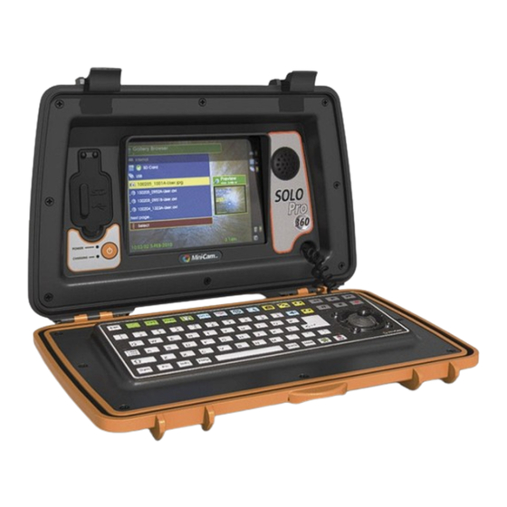
- Page 1 Pipeline Inspection System Users Guide Unit 4 Yew Tree Way Stonecross Park Golborne Warrington WA3 3JD United Kingdom Rev A - 04/2012 Page: 1...
- Page 2 Notice The information contained in this document is subject to change without notice. Mini-Cam Ltd. makes no warranty of any kind with regard to this material, including but not limited to, the implied warranties of merchantability and fitness for a particular purpose. Mini-Cam shall not be liable for errors contained herein or for incidental or consequential damages in connection with the furnishing, performance, or use of this material.
-
Page 3: Certification
This declaration is based on test report(s) of the relevant EMC testing laboratory. Operator Safety The SoloPro 360 Pan and Rotate camera has externally accessible moving parts. Please ensure that care is taken when handling the camera as, under certain circumstances, these parts can move without warning. -
Page 4: Fcc Declaration
FCC Declaration Note: This equipment has been tested and found to comply with the limits for a Class A digital device, pursuant to part 15 of the FCC Rules. These limits are designed to provide reasonable protection against harmful interference when the equipment is operated in a commercial environment. - Page 5 CONDITIONS OF THE LIMITED WARRANTY Disassembling the camera, coiler, control unit or any part of the system, without approval of the manufacturer, is forbidden! Non-compliance of this direction will result in the loss of the warranty. The beginning of the warranty period is the date of delivery. This limited warranty does not cover damage due to improper treatment of the system, inadequate maintenance, alteration, repair, normal wear and tear or external causes like lightning, fire or frost.
-
Page 6: Manual Conventions
WARNING Warning denotes a hazard. It calls attention to a procedure which, if not correctly performed or adhered to, could result in injury or loss of life. Do not proceed beyond a warning note until the indicated conditions are fully understood and met. CAUTION Caution denotes a hazard. -
Page 7: Table Of Contents
Table of Contents Certification......................3 CE Declaration ....................3 FCC Declaration ....................4 LIMITED WARRANTY ..................4 Manual Conventions ....................6 Preparing for Use .................... 9 What you'll find in this chapter ..............9 ... - Page 8 Service Centre ..................21 Gallery ......................22 What you'll find in this chapter .............. 22 Gallery Menu ..................22 Show/Play function ................23 Copy function ..................24 Rename ....................24 ...
-
Page 9: Preparing For Use
1 Preparing for Use 1.1 What you'll find in this chapter This chapter describes the process of getting the SOLO Pro 360 Pipeline Inspection System ready to use when you have just received it. 1.2 Initial Inspection Inspect the shipping container for damage. If the shipping container or cushioning material is damaged, keep it until you have verified that the contents are complete and you have tested your SOLO Pro 360 mechanically and electrically. -
Page 10: Physical Installation
more than 12 volts DC nominal. WARNING: Failure to ignore this will result in system damage and invalid any warranty. 1.5 Physical Installation To install the SOLO Pro 360 on to a push camera coiler align the two vertical pillars on the top of the coiler with the receptacles behind the aluminium plates on the lower rear of the SOLO Pro 360 unit and push down to locate. -
Page 11: Display Features
2 Display Features What you'll find in this chapter This chapter describes the characteristics of the front panel LCD display. 2.2 Introduction The front panel of the SOLO Pro 360 unit houses an 8” Liquid Crystal Display (LCD) which is used to display live and recorded video and on screen menus. -
Page 12: Status Icons
If po wer saving m mode is enable ed, the screen n backlight in ntensity will a utomatically reduce to a lo level if the keypad d is not used for a pre-set time period r returning to it ts normal inte ensity when a any key is pre... - Page 13 Rev A - 04/2012 Page: 13...
-
Page 14: Keyboard
3 Keyboard 3.1 What you'll find in this chapter This chapter describes how functions are selected from the keyboard. 3.2 Keyboard description. The keyboard may be divided into several sections as shown in Fig 3.1 (below). Zoom Key Illumination Sonde Control Key Snapshot Key Control Key Gallery browser... -
Page 15: Text Control Keys
Text Con ntrol Keys Thes e three keys a are used to c reate a repor rt pro-forma b by altering th e free text th at appears on n the scree en. This free t text is recorde ed on top of t the survey vid deo. -
Page 16: Snapshot Key
e current zoo om factor. Th is may be use ed whilst view wing live video o, recording, aying back re ecorded video Snapsho t Key his key genera ates a snapsh ot picture of the video cur rrently being displayed. -
Page 17: Text Entry Keyboard
his key is the F Function key y which allow s special func ctions to be se elected. An xample is the onscreen Tim me, Date and Meterage tex xt. By pressing followed d by key in the top row t this will allow w you to chan nge the colou... -
Page 18: Setup Menus
Thus the default filename can be set to be the company or industry standard and all recorded files will automatically be given a unique filename based on this default. An example filename is shown below:- 100106_1059-Minicam.avi Rev A - 04/2012 Page: 18... -
Page 19: Time And Date
This indicates that the file was recorded on the 6th January 2010 and started at 10:59. Mini-Cam is the default filename and .avi shows that the file is in the motion video AVI format Video File Format .AVI (MPEG4) is a motion video file which can be played back using WinCan v7 and v8, Windows Media Player and most other third party readers. -
Page 20: Power Saving
4.6 Power Saving This menu allows the user to set the power saving features of the SOLO Pro 360. Camera and LCD Dimming The camera illumination and LCD backlight will dim after a period of inactivity. The options are: Never / 5 / 15 / 30 minutes. Automatic Shutdown When the SOLO Pro is powered only by internal batteries this feature will power down the SOLO Pro after a period of inactivity. -
Page 21: Service Centre
greyed out in the menu. 4.9 Service Centre This menu option is for sole use by Mini-Cam and its authorised dealers. As such, this option is password protected. Rev A - 04/2012 Page: 21... -
Page 22: Gallery
5 Gallery 5.1 What you'll find in this chapter This chapter describes how the key is used to access and manipulate recorded survey video files. 5.2 Gallery Menu Pressing the key displays a menu that shows which of the three main memory types is being used and the contents of that memory type. -
Page 23: Show/Play Function
Selected memory type The ‘tick’ next to one of the memory types shows which one is selected for viewing and where the video files are automatically recorded to. To change the selected memory type, move the cursor so that a new memory type is highlighted in yellow. -
Page 24: Copy Function
5.4 Copy function With the copy function the user to copy all files from one memory type to another, e.g. Copy all files from the Internal memory to the external USB memory. It is also possible to copy a daily directory or individual file directly to another media. To use this function open the Gallery Browser and highlight the source memory, daily directory, or file then press down on the joystick. -
Page 25: Un-Mounting External Memory
5.7 Un-mounting external memory Before any external memory device (SD card or USB memory stick) is removed from the unit, it must be un-mounted. To do this open the Gallery and select the memory which needs to be removed using the up and down actions on the joystick. -
Page 26: Recorder Control Keys
Recorder r Control Keys What yo u'll find in n this chapt This chapter desc ribes the func ctions of the Recorder Con ntrol Keys and d how these can be used t make e recordings a and control t he playback o of stored surv veys. -
Page 27: Fast Rewind
to in crease to the e fastest playb back speed of f 12 times no rmal speed (x x12). To retur rn to normal playb back speed p ress play key To re educe the fas t forward spe eed, press the e rewind key , each pres ss reducing th... -
Page 28: Text Entry, Symbols And Graphics
Text Ent ry, Symbo ols and G Graphics What yo u'll find in n this chapt This chapter des scribes the w way in which h free text an nd onscreen n graphics m may be entere ed on to th he screen fo r recording with the sur... -
Page 29: Pages
appe ear at the curs sor position a and the curso or will automa atically move one place to the left ready y for the n next characte Press sing ‘carriage return’ will c cause the curs sor to move d down and ba ck to the beg ginning of the... -
Page 30: Pan & Rotate Camera
8 Pan & Rotate Camera 8.1 What you’ll find in this chapter This chapter describes the operation and control of the Pan & Rotate camera on the SOLO Pro 360. 8.2 Basic camera operation When the SOLO Pro 360 CCU is first switched on the joystick is in a default cursor mode to drive the on screen text and menu system. -
Page 31: Camera Pressurisation
Pressing the menu key when the joystick camera control is enabled will automatically disable it to allow the operator control of the menu system. The operator must enable the joystick camera control manually afterwards. 8.3 Camera Pressurisation To pressurise the Pan & Rotate camera it must be connected to the SOLO Pro 360. If not already done so, follow the guide in section 8.2 to get the camera working first. - Page 32 Attention: Your product is marked with this symbol. It means that used electrical and electronic products should not be mixed with general household waste. There is a separate collection system for these products. Information on Disposal for Business Users: Attention: If you want to dispose of this equipment, please do not use the ordinary dust bin! Used electrical and electronic equipment must be treated separately and in accordance with legislation that requires proper treatment, recovery and recycling of...
Need help?
Do you have a question about the SoloPro 360 and is the answer not in the manual?
Questions and answers