Table of Contents
Advertisement
Quick Links
®
Flavor Burst
Integrated Cabinet
Compatible with Taylor C201 Cart
- Operations Manual Supplement
Models: CTP 80SS-INT
CTP 80BLD-INT
CTP 80BEV-INT
CTP 80FCB-INT
Manufactured by
Flavor Burst Company
499 Commerce Drive
Danville, IN 46122
For general information and to locate a
distributor near you, call or visit our
website:
Phone: (317) 745-2952
Toll Free Number: (800) 264-3528
Fax: (317) 745-2377
www.flavorburst.com
For pricing, ordering and support, contact
one of our qualified distributors.
This supplement is not a full operations manual. It does not contain complete
information on installing and maintaining your new system. The purpose of
this manual supplement is to provide you with additional information and
instruction, such as diagrams and part lists, which are either not included or
are different from what is shown in the standard manual. Read through these
installation and maintenance instructions first and then refer to your standard
manual for the rest of the instructions. Be sure to also refer to your standard
model to get complete information needed for your system.
All manuals and supplements are available on
©2015 Flavor Burst Company
All Rights Reserved
PLEASE READ FIRST!
Printed in September
www.flavorburst.com
Printed in
The United States of America
Advertisement
Table of Contents

Subscribe to Our Youtube Channel
Related Manuals for Flavor Burst CTP 80SS-INT

Summary of Contents for Flavor Burst CTP 80SS-INT
- Page 1 ® Flavor Burst Integrated Cabinet Compatible with Taylor C201 Cart - Operations Manual Supplement Models: CTP 80SS-INT CTP 80BLD-INT CTP 80BEV-INT CTP 80FCB-INT Manufactured by Flavor Burst Company 499 Commerce Drive Danville, IN 46122 For general information and to locate a...
- Page 2 PAGE INTENTIONALLY LEFT BLANK...
-
Page 3: Table Of Contents
TABLE OF CONTENTS FCC ID……………………………...………………………………………….………………...3 Introduction……………………………...………………………………………….………….4 Safety Precautions……………………………..…………….………..……..….…………..4 Environmental Notices………………...………………………………………….………….5 Parts Identification/Function……...……………………….……..…..……….……..….…..7 Equipment Setup……………………………………………………...…..……….……..….36 Installing the Integrated Cabinet, Unit Syrup Line and Pump Harness Cable…..36 Filling the Sanitizer Tank………………………………………….……………..…40 EQUIPMENT SETUP – Continued……………………………………………..…41 Other Important Information…………….…….…...……………………..…...……..…..42 Ordering/Service Information…………….…….…...………………………...……..…..43... -
Page 4: Fcc Id
FCC ID 必须要加的警告语: This device complies with Part 15 of the FCC Rules. Operation is subject to the following two conditions: (1) this device may not cause harmful interference, and (2) this device must accept any interference received, including interference that may cause undesired operation. Changes or modifications not expressly approved by the party responsible for compliance could void the user's authority to operate the equipment. -
Page 5: Introduction
Failure to follow this instruction may result in very simple. Select a flavor from the Touch electrocution or damage to the machine. Panel and draw the product. The Flavor Burst Consult your electrician. system will automatically flavor the product at the spout. -
Page 6: Environmental Notices
HAZARD COMMUNICATION STANDARD (HCS) – The procedure(s) in this manual NOTE: Access to the service area is restricted to persons having safety / hygiene include the use of chemical products. These knowledge and practical experience of the chemical products will be highlighted in appliance. - Page 7 PAGE INTENTIONALLY LEFT BLANK...
-
Page 8: Parts Identification/Function
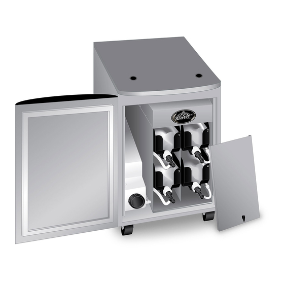
General Cabinet Overview (See Figure 1) ITEM PART NO. DESCRIPTION QTY. FUNCTION TOUCH PANEL ASSEMBLY WITH ELE 905A Flavor Burst unit command center. BRACKET ELE 434 POWER CABLE Supplies the electronics board with power. FOR “SS” SYSTEMS: Injects syrups into the product. - Page 9 *The Modified Back Panel may be included with the Taylor C201 if the Flavor Burst system was purchased in conjunction with the Taylor cabinet. If integrated cabinet system was bought separately, the Modified Back Panel should be included with the Flavor Burst cabinet to replace the existing one on your Taylor C201 mobile cabinet.
- Page 10 PAGE INTENTIONALLY LEFT BLANK...
- Page 11 General Cabinet Overview 26000 “FCB” SYSTEMS “BEV” SYSTEMS “BLD” SYSTEMS “SS” SYSTEMS “SS” AND “BLD” “SS” AND SYSTEMS “BLD” “SS” & “BLD” “BEV” & “FCB” SYSTEMS SYSTEMS SYSTEMS “SS” SYSTEMS 13-1 “BLD” SYSTEMS 13-2 13-3 “BEV” SYSTEMS 13-4 “FCB” SYSTEMS Figure 1...
- Page 12 Integrated Cabinet (See Figure 2) ITEM PART NO. DESCRIPTION QTY. FUNCTION Connects and secures the side and CAB 357 PANEL STABILIZER BRACKET interior panels of the internal cabinet. CAB 304L LEFT SIDE CABINET PANEL Holds left side syrup rails. CAB 304R RIGHT SIDE CABINET PANEL Holds right side syrup rails.
- Page 13 Integrated Cabinet (See Figure 2) ITEM PART NO. DESCRIPTION QTY. FUNCTION Transports syrup from bags to the 9- SYR 927 INTERNAL 9-TUBE ASSEMBLY Tube Assembly. FAS 2024 8-32 X 1/4 PAN HEAD SCREW Secures various parts within the system. CAB 355 SYRUP PUMP SHELF Secures the pumps within the cabinet.
- Page 14 “SS” Injector Assembly and Related Parts (See Figure 3A) ITEM PART NO. DESCRIPTION QTY. FUNCTION FOR “SS” SYSTEMS: Injects syrups into the INJECTOR ASSEMBLY WITH SYRUP product. INJ 424TS LINES, ADAPTER, & BRACKET *1 for 80SS systems. **0 for 80BEV, 80BLD, & 80FCB systems. Connects flavor line to inject syrups into INJ 422 INJECTOR HEAD ASSEMBLY...
- Page 15 “SS” Injector Assembly and Related Parts (Continued) ITEM PART NO. DESCRIPTION QTY. FUNCTION INJ 323TS INJECTOR ASSEMBLY - NO HEAD Powers Injector system. INJ 330TS INJECTOR MOTOR ASSEMBLY 1 ea. Supplies power to Motor which turns gears. Gears turn Gear Cartridge for even syrup INJ 331 INJECTOR GEARBOX ASSEMBLY 1 ea.
- Page 16 “BLD” Blending Assembly and Related Parts (See Figure 3B) ITEM PART NO. DESCRIPTION QTY. FUNCTION FOR “BLD” SYSTEMS: Blends syrups into FLAVOR BLEND BLENDING the product. INJ 424VBLD ASSEMBLY WITH SYRUP LINES, *1 for 80BLD systems. ADAPTER, & BRACKET **0 for 80SS, 80BEV, & 80FCB systems. ADPT 101A BLENDING ADAPTER W/ O-RINGS Attaches Blending Assembly to freezer door.
- Page 17 “BLD” Blending Assembly and Related Parts (Continued) ITEM PART NO. DESCRIPTION QTY. FUNCTION MIS 3143 SUSPENSION BRACKET ASSEMBLY Secures Blending Assembly to freezer door. FAS 2107 BLENDING BRACKET KNOB 1 ea. Secures the two bracket pieces. Attaches to freezer door bolts to hang MIS 3143A SUSPENSION BRACKET PART A 1 ea.
- Page 18 “BEV” Blending Assembly and Related Parts (See Figure 3C) ITEM PART NO. DESCRIPTION QTY. FUNCTION FOR “BEV” SYSTEMS: Blends syrups into VERTICAL BLENDING ASSEMBLY the product. INJ 424VTS WITH SYRUP LINES, ADAPTER, & *1 for 80BEV systems. BRACKET **0 for 80SS, 80BLD, & 80FCB systems. Connects flavor line to inject syrups into INJ 422 BLENDING HEAD ASSEMBLY...
- Page 19 “BEV” Blending Assembly and Related Parts (Continued) ITEM PART NO. DESCRIPTION QTY. FUNCTION INJ 323TS BLENDING ASSEMBLY - NO HEAD Powers Blending system. INJ 330TS BLENDING MOTOR ASSEMBLY 1 ea. Supplies power to Motor which turns gears. Gears turn Gear Cartridge for even syrup INJ 331 BLENDING GEARBOX ASSEMBLY 1 ea.
- Page 20 “FCB” Door Spout Assembly and Related Parts (See Figure 3D) ITEM PART NO. DESCRIPTION QTY. FUNCTION FOR “FBC” SYSTEMS: Dispenses product ADPT MODIFIED FCB FREEZER SPOUT blended with syrups. TY80S-FCB ASSEMBLY *1 for 80FCB systems. **0 for 80SS, 80BEV, & 80BLD systems. MODIFIED DOOR SPOUT FCB 112 Dispenses product mixed with flavorings.
- Page 21 “FCB” Door Spout Assembly and Related Parts 26003D FOR “FCB” SYSTEMS Figure 3D...
- Page 22 Soft Serve Syrup Pump and Related Parts (See Figure 4A) ITEM PART NO. DESCRIPTION QTY. FUNCTION FOR “SS” & “BLD” SYSTEMS: Pumps SOFT SERVE SYRUP PUMP syrup from flavor bags into flavor lines. SYSTEM *8 for 80SS & 80BLD, systems. **0 for 80BEV &...
- Page 23 Beverage Syrup Pump and Related Parts (See Figure 4B) ITEM PART NO. DESCRIPTION QTY. FUNCTION FOR “BEV” & “FCB” SYSTEMS: Pumps BEVERAGE SYRUP PUMP syrup from flavor bags to flavor lines. SYSTEM *8 for 80BEV & 80FCB systems. **0 for 80SS & 80BLD, systems SHAKE SYRUP PUMP 1 ea.
- Page 24 Sanitizer Pump and Related Parts (See Figure 5) ITEM PART NO. DESCRIPTION QTY. FUNCTION FOR “SS” and “BLD” SYSTEMS: Flushes MIS 3028- SANITIZER FLUSH TUBE flavor lines with sanitizer when attached. ASSEMBLY – SOFT SERVE INT *1 for 80SS & 80BLD systems. **0 for 80BEV &...
- Page 25 Sanitizer Pump and Related Parts (Continued) 26005 “SS” & “BLD” “BEV’ MODELS “FCB” MODELS MODELS TO SANITIZER TANK TO 9-TUBE LEAD TO SANITIZER TANK Figure 5...
- Page 26 Syrup Tray, Sanitizer Tank, 9-Tube Assembly Lead, and Casing (See Figure 6) ITEM PART NO. DESCRIPTION QTY. FUNCTION Transports syrup from bags to the 9-Tube SYR 927 INTERNAL 9-TUBE ASSEMBLY Assembly. Transports syrup and sanitizer from SYR 900 4' 9-TUBE ASSEMBLY TUBES 9 ea.
- Page 27 Syrup Tray, Sanitizer Tank, 9-Tube Assembly Lead, and Casing 26008 PUMPS Figure 6...
- Page 28 Electronic Parts and Connections (See Figure 7) ITEM PART NO. DESCRIPTION QTY. FUNCTION FLAVOR 10 COLOR TOUCH PANEL ELE 905 Control system for the unit. FOR “SS” & “BLD” SYSTEMS: Secures the TOUCH PANEL MOUNTING BRACKET Touch Panel to the freezer. MIS 3214 ASSEMBLY *1 for 80SS &...
- Page 29 Electronic Parts and Connections (Continued) ITEM PART NO. DESCRIPTION QTY. FUNCTION FOR “FCB” SYSTEMS: Activates the syrup pumps when draw handle is activated. ELE 530 FCB SPIGOT SWITCH ASSEMBLY KIT *1 for 80FCB systems. 0 for 80SS, 80BLD, & 80BEV systems. MIS 3179 FCB MAGNETIC ACTUATOR PIN 1 ea.
- Page 30 *The Modified Back Panel (#1) may be included with the Taylor C201 if the Flavor Burst system was purchased in conjunction with the Taylor cabinet. If the your integrated cabinet system was bought separately, the Modified Back...
- Page 31 Electronic Parts and Connections 26002 14-1 14-2 Figure 7...
- Page 32 “SS” Spare Parts Kit (See Figure 8A) ITEM PART NO. DESCRIPTION QTY. FUNCTION FOR “SS” SYSTEMS: Houses extra spare parts and wear items. SPR 5800A SPARE PARTS KIT – SOFT SERVE *1 for 80SS systems. **0 for 80BLD, 80BEV, & 80FCB systems. CW 137 DRIVE MOTOR GEAR Turns gear box gears, powered by the motor.
- Page 33 “BLD” Spare Parts Kit (See Figure 8B) ITEM PART NO. DESCRIPTION QTY. FUNCTION FOR “BLD” SYSTEMS: Houses extra spare SPARE PARTS KIT – SOFT SERVE parts and wear items. SPR 5800BLD BLEND *1 for 80BLD systems. **0 for 80SS, 80BEV, & 80FCB systems. Turns the gear box gears, powered by the CW 137 DRIVE MOTOR GEAR...
- Page 34 “BEV” Spare Parts Kit (See Figure 8C) ITEM PART NO. DESCRIPTION QTY. FUNCTION FOR “BEV” SYSTEMS: Houses extra spare SPARE PARTS KIT – parts and wear items. SPR 5800BEV TOUCHSCREEN BEVERAGE *1 for 80BEV systems. **0 for 80SS, 80BLD, & 80FCB systems. ELE 444 1 AMP, 1 1/4"...
- Page 35 “FCB” Spare Parts Kit (See Figure 8D) ITEM PART NO. DESCRIPTION QTY. FUNCTION FOR “FCB” SYSTEMS: Houses extra spare parts and wear items. SPR 5800FCB SPARE PARTS KIT FOR FCB *1 for 80FCB systems. **0 for 80SS, 80BEV, & 80BLD systems. ELE 444 1 AMP, 1 1/4"...
- Page 36 PAGE INTENTIONALLY LEFT BLANK...
-
Page 37: Equipment Setup
Included is a modified back panel that replaces NOTE: INSPECT ALL WEAR ITEMS AND the Taylor cabinet back panel to accommodate REPLACE IF NECESSARY. Flavor Burst’s tubing and electronics wiring. Follow the instructions below to set up the NOTE: THE FOLLOWING PROCEDURES Flavor Burst cabinet and connections. - Page 38 Connect the harness to the port on the 26403 electronics board labeled “BANK A” or “PWRCONN2”. 26436 4. Angle the Flavor Burst cabinet inside the Taylor cabinet, taking care not to pinch or damage the tubing and pump wires. 26404 8. Locate the 9-Tube Lead under the electronics panel and remove the dust cap.
- Page 39 11. Slide the coupler casing over the connection 14. Slide the integrated cabinet as far into the and screw each coupler nut into each end of Taylor cabinet as it will go with the lip of the the casing. Tighten the coupler nuts to electronics panel hanging over the edge, secure the connection.
- Page 40 17. Clean, rinse and dry the Taylor cabinet’s 20. Locate the power entrance module cable on inside corner brace on the same side the 9- the inside of the Taylor back panel. It has Tube Assembly is installed. Use detergent two thin cables attached to a small white water, clean water and single service plastic connector.
-
Page 41: Filling The Sanitizer Tank
Sanitizer Tank. The tank system delivers solution to specific areas of the 26412 ® Flavor Burst system such as the Spout Assembly and syrup lines during certain functions. In order to utilize these clean-in- place functions, keep an adequate supply of approved sanitizer solution in the Sanitizer Tank at all times. -
Page 42: Equipment Setup - Continued
EQUIPMENT SETUP – Continued 4. Set the Sanitizer Tank upright and remove the cap. Continue with the EQUIPMENT SETUP instructions in your standard operations 26242 manual(s). For systems flavoring two different product types, refer to each type of manual for setup on that freezer. -
Page 43: Other Important Information
OTHER IMPORTANT INFORMATION Consult your standard manual for important information and instructions on these topics: Daily Opening Procedures Daily Closing Procedures Replacing the Syrup Flavors Scheduled Maintenance Color Touch Panel Overview Directory of Cleaning Procedures ... -
Page 44: Ordering/Service Information
For more information, contact your local ® authorized Flavor Burst distributor. Flavor Burst is a registered trademark of the Flavor Burst Company. Taylor is a registered trademark of the Taylor Company. All rights reserved.
Need help?
Do you have a question about the CTP 80SS-INT and is the answer not in the manual?
Questions and answers