Table of Contents

Related Manuals for FRC OPTIMUM

Summary of Contents for FRC OPTIMUM
- Page 1 LGT100 Rev0309 Document Number: XM-LGT1PM-R0A GENERAL LIGHTING OPTIMUM FOCUS NIGHTMASTER FIRE RESEARCH CORPORATION www.fireresearch.com 26 Southern Blvd., Nesconset, NY11767 TEL ( 631 ) 724-8888 FAX ( 631 ) 360-9727 TOLL FREE 1-800-645-0074...
-
Page 2: Table Of Contents
Install Quick Release Bracket for Portable Model 700 ........22 Install Brow Mount Models 800, 850 ..............24 MAINTENANCE ..................... 26 Bulb Replacement Optimum and Focus .............. 26 Cleaning ....................... 26 Bulb Replacement NightMaster................28 Bulb Replacement Triple Cluster ................. 28 NO-SCRATCH FOR MODEL 530 TELESCOPIC POLE ........ - Page 3 Figure 8. Install Portable Light Quick Release Bracket .......... 23 Figure 9. Install Contour and Flat Brow Mounts ............. 25 Figure 10. Bulb Replacement Optimum and Focus ..........27 Figure 11. Bulb Replacement NightMaster ............. 29 Figure 12. No-Scratch ..................... 31 Figure 13.
-
Page 4: Introduction
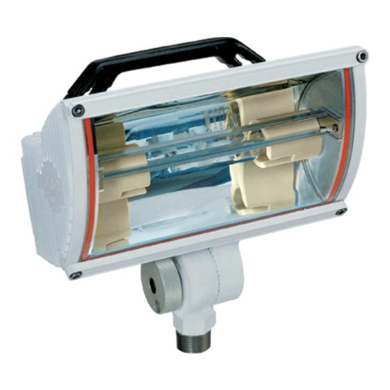
Overview OPTIMUM Lampheads utilize a super-efficient design to offer a maximum transfer of light from bulb to scene. The newest addition to the FRC lighting series includes HIR and HID bulb options not available on classic Focus lights. FOCUS Low Profile Lampheads introduced the concept of re-directing light with 50 parabolic curved and aimed surfaces. -
Page 5: Specifications
LGT100 Rev0309 Specifications Note: All Optimum, Focus, and NightMaster lampheads are available seperately or as part of a lighting assembly. Table 1. Lamphead Guide Series O=Optium Lapmhead Bulb Type Watts Volts Amps F=Focus Style L=NightMaster O, F O, F 12.5 6.25... -
Page 6: Safety Summary
LGT100 Rev0309 SAFETY SUMMARY FRC lighting products are engineered and manufactured with safety in mind. It is critical that FRC scene lights are installed, maintained, and operated correctly. Read and understand all instructions before installing, performing maintenance, or operating. All components, equipment, and installation procedures shall conform to NFPA 1901, Standard for Automotive Fire Apparatus and NFPA 70 National Electrical Code. - Page 7 LGT100 Rev0309 Operation Safety Precautions Operate portable lighting products only from the type of power source indicated on the identification label. During operation use the handle to move the light, the housing will be extremely hot. Ensure that all lighting components are clear of obstructions when raising telescopic poles.
-
Page 8: Installation Instructions
LGT100 Rev0309 INSTALLATION INSTRUCTIONS Install Lamphead on Telescopic Pole Lampheads and telescopic poles are shipped apart and need to be assembled Note: The 512 telescopic pole must be installed before the lamphead is attached if the small diameter hole is used. Refer to Install Models 510, 512 Top Mount Telescopic Poles. -
Page 9: Figure 1. Assemble Lamphead And Telescopic Pole
WHITE GREEN SILVER BRAID Green Wire Optimum lamphead only. Slide the lamphead assembly onto the pole. Make sure that the wires are not caught and squeezed by the lip of the pole. Loop the excess wire in a zig-zag to take up the slack and tuck into the pole Dimension A should be less than 0.015"... -
Page 10: Install Recessed Mount Models 200, 230, 250
LGT100 Rev0309 Install Recessed Mount Models 200, 230, 250 1. Measure and mark mounting location for cutout. 2. Cut out mounting hole. 3. Place the light in position to check for fit and mark mounting screw locations. 4. Double check the clearance around and behind the light housing. Recessed lights require a minimum of 3 inch clearance between wall insulation and the light housing. -
Page 11: Table 2. Recessed Mount Dimensions
LGT100 Rev0309 Table 2. Recessed Mount Dimensions Model FCA200- D15, H30, S30, S50, S72, S75 5 5/8 9 3/4 4 1/4 D30, M10, M12, M15 17 1/2 5 5/8 16 1/8 4 1/4 OPA200- S30, S50, S72, S75 5 5/8 9 3/4 4 1/4 M10, M12, M15, R90... -
Page 12: Install Aerial Mount Models 300
LGT100 Rev0309 Install Aerial Mount Models 300 Before mounting check the identification label on the lamphead for specific voltage and current requirements. Check that the length of the power cord is correct. Note: Before drilling holes place the light in position to check for fit. Ensure that the lamphead will clear all obstructions. -
Page 13: Figure 3. Install Under Aerial Mount
LGT100 Rev0309 Adjust the lamphead angle by loosing the nuts at the bracket pivot point. Required Clearance Aimed directly forward 4 inches Aimed at 30° downward 6.5 inches Aimed at 45° downward 6.75 inches Aimed directly down 7.5 inches Note: It is best to use the lamphead and attached brackets as a template to mark mounting holes. -
Page 14: Install Top Mount Telescopic Pole Models 510, 512
LGT100 Rev0309 Install Top Mount Telescopic Pole Models 510, 512 When positioning a telescopic pole ensure that the lamphead will clear all obstructions and the twist lock will be accessible. Note: The 512 telescopic pole should be installed before the lamphead is attached. -
Page 15: Figure 4. Install Top Mount Telescopic Pole
LGT100 Rev0309 1 3/4" Top Mount Diameter Cutout 1 7/8" Flange Diameter 3 1/4" Round or Square Flange 2 5/8" Hardware Recommendations Drawings may not be to scale. For 510, 512 mounts: DO NOT USE AS A TEMPLATE 1/4-20 SS 1 5/8"... -
Page 16: Install Side Mount Telescopic Pole Models 530, 540, 542
LGT100 Rev0309 Install Side Mount Telescopic Pole Models 530, 540, When positioning a telescopic pole ensure that the lamphead will clear all obstructions and the twist lock will be accessible. 1. Place the light in position to check for fit and freedom of operation. 2. -
Page 17: Figure 5. Install Side Mount Telescopic Pole
LGT100 Rev0309 530, 540, 542 Side Mount Brackets 3" 2 1/8" 1 1/2" 3" Side Mount Bracket Footprint The footprint is the same for all side mount and steady rest brackets. Drawings may not be to scale. DO NOT USE AS A TEMPLATE Hardware Recommendations For 530, 540, 542 mounts: 530, 540, 542... -
Page 18: Install Pedestal Mount Models 570, 580
LGT100 Rev0309 Install Pedestal Mount Models 570, 580 When positioning a pedestal mount light ensure that the lamphead will clear all obstructions. 1. Place the light in position to check for fit and freedom of operation. 2. Mark the footprint of the mounting flange/bracket. 3. -
Page 19: Figure 6. Install Pedestal Mount
LGT100 Rev0309 5/8" Diameter Pedestal Mount Cutout Flange Diameter 3 1/2" 2 7/8" Hardware Recommendations For 570, mounts: 1/4-20 SS Drawings may not be to scale. DO NOT USE AS A TEMPLATE Side Mount Brackets Hardware Recommendations For 580, mounts: 5/16-18 SS 3"... -
Page 20: Install Quick Release Bracket Set For Tripod Models 600, 642, 656
Install Quick Release Bracket Set for Tripod Models 600, 642, 656 The quick release mounting bracket set will hold an FRC tripod securely on the vehicle. The mounting bracket set consists of a lower base into which the bottom of the tripod legs rest, and an upper locking bracket, which has a quick release knob on the right side. -
Page 21: Figure 7. Install Tripod Quick Release Bracket Set
LGT100 Rev0309 Align the left sides of the brackets and the left side mounting Total distance from holes for the tripod to top to bottom of fit correctly. mount brackets: 43 1/2" for 600, 656 30 1/4" for 642 The pull knob Tripods with must be to the Focus lampheads... -
Page 22: Install Quick Release Bracket For Portable Model 700
LGT100 Rev0309 Install Quick Release Bracket for Portable Model 700 The quick release brackets will hold an FRC portable lamphead securely to the vehicle or a telescopic pole. Pull the quick release knob to install or remove the portable light. -
Page 23: Figure 8. Install Portable Light Quick Release Bracket
LGT100 Rev0309 Quick Release Bracket for Hardware Recommendations For 703 mounts: Flat Surface Mountingt 5/16-18 SS 2" 3 1/8" Base with Focus lamphead 3 3/8" 2 1/4" shown on a 703 quick release bracket. Quick Drawings may not be to scale. Release DO NOT USE AS A TEMPLATE Quick... -
Page 24: Install Brow Mount Models 800, 850
LGT100 Rev0309 Install Brow Mount Models 800, 850 Before mounting check the identification label on the lamphead for specific voltage and current requirements. Check that the length of the power cord is correct. Note: Before drilling holes place the light in position to check for fit. Ensure that the lamphead will clear all obstructions. -
Page 25: Figure 9. Install Contour And Flat Brow Mounts
LGT100 Rev0309 FCA800 TYPICAL INSTALLATION Contour Mount OPA800 Note: It is best to use the lamphead and attached brackets as a template to mark mounting holes. Hardware Recommendations For 800, 850 mounts: 1/4-20 or 5/16-18 SS FCA850 Flat Mount OPA850 Figure 9. -
Page 26: Maintenance
3. Hold the glass in place while removing the bezels. Remove the four cap head screws and remove the bezels. Remove the glass. Note: Optimum gasket is attached, the Focus gasket may come off. 4. Slide the bulb sideways into the spring contact and lift it out from the opposite side. -
Page 27: Figure 10. Bulb Replacement Optimum And Focus
Failure to do so may result in racking the glass when the screws are tightened. FOCUS Housing LAMPHEAD Gasket Bulb Glass Bezel Screw Splice in gasket should be down. Figure 10. Bulb Replacement Optimum and Focus... -
Page 28: Bulb Replacement Nightmaster
LGT100 Rev0309 Bulb Replacement NightMaster 1. Ensure power is OFF and the lamphead is cool to the touch prior to replacing the bulb. 2. Ensure the replacement bulb has the same voltage and wattage rating. 3. Loosen the two screws on each side of the lamphead. Open the glass cover (the gasket may also come off). -
Page 29: Figure 11. Bulb Replacement Nightmaster
LGT100 Rev0309 NIGHTMASTER LAMPHEAD Screw Glass Glass Cover Cover Hinge Smaller NightMaster lampheads will have two screws on the side. Larger lampheads will have two screws on the top. NIGHTMASTER Black White Triple Cluster Wire Wire PAR 46 Bulb Wire Rear View of Bulb Figure 11. -
Page 30: No-Scratch For Model 530 Telescopic Pole
LGT100 Rev0309 NO-SCRATCH FOR MODEL 530 TELESCOPIC POLE Install No-Scratch Guide Collar and Guide Rail 1. Install the telescopic pole according to instructions for side mouint telescopoic pole. Note: It is recommended that the Steady Rest Bracket be installed with the No-Scratch option. -
Page 31: Figure 12. No-Scratch
LGT100 Rev0309 As the Pole is Raised the guide collar disengages from the guide rail and the lamphead is free to rotate 360°. As the Pole is Lowered the guide collar engages the guide rail and prevents the pole from being lowered unless the lamphead is correctly aligned. -
Page 32: Raised Pole Warning Switch And Indicator
LGT100 Rev0309 RAISED POLE WARNING SWITCH AND INDICATOR Overview The raised pole warning switch is a normally closed magnetic switch mounted on the outer pole. A magnet, mounted on the inside of the inner pole, keeps the switch contact open when the pole is in the down position (see Diagram 1). When the light is raised the magnet moves with the inner pole away from the switch and the contact closes (see Diagram 2). -
Page 33: Description
LGT100 Rev0309 Description Specifications Switch Contact Single Pole Single Throw (SPST) Position Normally Closed (NC) Current 0.25 AMPS Power 3 WATTS CAUTION: If the switch is to be used with a higher current application a relay must be provided to avoid switch failure. Indicator Type 1891... -
Page 34: Parts List
LGT100 Rev0309 Parts List Part Number Description LT-S100 Kit, Raised Pole Warning, 510 Poles . LT-S347SW . Switch Assembly, Top Flange, Magnetic, NC . LT-S347C-SW . Switch Assembly, Top Flange C/E, Magnetic, NC . LT-S337 . Magnet, Inner Pole . LT-SZL606 . - Page 35 LGT100 Rev0309 This page intentionally left blank.
Need help?
Do you have a question about the OPTIMUM and is the answer not in the manual?
Questions and answers