Table of Contents
Advertisement
Quick Links
Advertisement
Table of Contents

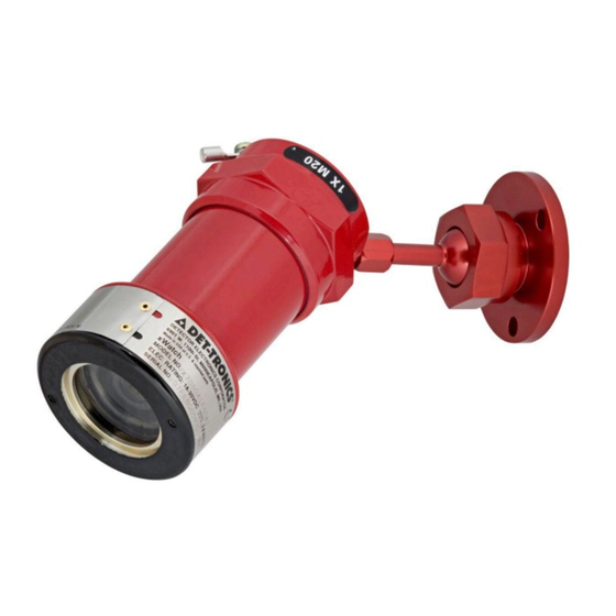
Summary of Contents for Carrier DET-TRONICS xWatch X7050
- Page 1 Instructions xWatch Explosion-Proof Camera ® Model X7050 Rev: 3/12 95-8600...
-
Page 2: Table Of Contents
Table Of Contents DESCRIPTION . . . . . . . . . . . . . . . . . . . . . . . . . . . . . . . . . . . . . . . . . . . . 1 FEATURES . -
Page 3: Description
INSTRUCTIONS xWatch Explosion-Proof Camera ® Model X7050 IMPORTANT Be sure to read and understand the entire i n s t r u c t i o n m a n u a l b e fo re i n s ta l l i n g o r operating the system. -
Page 4: General Application Information
GENERAL APPLICATION The monitor end must terminate the video cable with 100 INFORMATION ohms. Since most monitors have a built-in termination resistor of 75 ohms instead of 100 ohms, a balun or other The xWatch Explosion-Proof Camera Model X7050 has matching network (video converter) must be used. -
Page 5: Specifications
SPECIFICATIONS CERTIFICATIONS— OPERATING TEMPERATURE— ® –20°C to +70°C APPROVED HAZARDOUS LOCATION RATING— For complete approval details for the xWatch Explosion –40°C to +75°C Proof Camera Model X7050, refer to the appropriate Appendix: STORAGE TEMPERATURE— –30°C to +80°C Appendix A - FM/CSA Appendix B - ATEX/IECEx. -
Page 6: Important Safety Notes
IMPORTANT SAFETY NOTES INSTALLATION WARNING CAUTION Do not open the camera assembly in a hazardous Installation and wiring of the Model X7050 Camera area when power is applied. The device contains should be performed only by qualified personnel. no serviceable components and should not be opened, except during installation and setup. -
Page 7: Camera Location
CAMERA LOCATION Video Cable Considerations Cameras should be positioned to provide the best Proper video cable will ensure that the best quality video unobstructed view of the area to be monitored. If the is displayed on a remote monitor. Because composite camera is to monitor the same area as the detector, video frequencies span the range of 25 Hz to 6 MHz, it should be mounted as close to the detector as... -
Page 8: Wiring Procedure
WIRING TERMINAL BLOCK CAMERA MODULE INDEX PIN O-RING (2) HOUSING COVER TERMINAL CAP QUICK CONNECT PLUG (4) A2366 Figure 5—Exploded View of xWatch Camera WIRING PROCEDURE 4. Check all field wiring to be sure that the proper CAUTION connections have been made. Power must not be applied to the device while opening the housing or while plugging in or 5. -
Page 9: Aiming The Camera
AIMING THE CAMERA LEVELING THE CAMERA In installations where the Model X7050 Camera is used If the image on the monitor does not appear to be level, for monitoring the same hazardous area as a single this can be corrected by rotating the camera module detector, the recommended procedure for ensuring within the xWatch Camera. -
Page 10: Converting A C7050 Flame Detector To A Model X7050
CONVERTING A C7050 FLAME 3. Remove the existing UV module from the C7050 DETECTOR TO A MODEL X7050 detector. CAMERA 4. Disconnect the existing wiring at the controller. Connect the grounding strap between the new The Model X7050 Camera module can be installed in index pin and the terminal mounting screw per the place of the UV tube module in an existing C7050 Flame instructions. -
Page 11: Troubleshooting
TROUBLESHOOTING MAINTENANCE The xWatch Camera is not designed to be repaired in the CLEANING field. If it is determined that the problem is caused by The camera requires no periodic calibration or servicing. an electronic defect, the device must be returned to the However, the camera lens should be cleaned on a regular factory for repair. -
Page 12: Device Repair And Return
DEVICE REPAIR AND RETURN REPLACEMENT PARTS Part Number Description Prior to returning devices, contact the nearest local Detector Electronics office so that a Return Material 009448-003 Model DE2020N – Identification (RMI) number can be assigned. Replacement Camera Module, 2.33 mm, NTSC written statement describing the malfunction must 009448-004 Model DE2020P –... -
Page 13: Xwatch Model Matrix
xWATCH MODEL MATRIX MODEL DESCRIPTION X7050 xWatch Explosion Proof Camera TYPE MATERIAL Aluminum Stainless Steel (316) TYPE THREAD TYPE 1/2’ NPT TYPE VIDEO OUTPUT NTSC TYPE FIELD OF VIEW Wide FOV (90°), 2.3 mm Lens* Normal FOV (50°), 4.3 mm Lens Narrow FOV (30°), 8.0 mm Lens TYPE APPROVALS... -
Page 14: Appendix A - Fm / Csa Approval
APPENDIX A FM / CSA APPROVAL FM CERTIFICATION CERTIFICATE OF COMPLIANCE - Hazardous (Classified) Location Electrical Equipment Explosion-proof for Class I, Division 1, Groups B, C, and D; and dust ignition-proof for Class II/III, Division 1, Group E, F, and G T5 Ta = 75°C hazardous (classified) locations, indoors and outdoors (Type 4X). APPLICABLE STANDARDS Electrical and Electronic Test, Measuring and Process Control Equipment, Class 3810, 2005. -
Page 15: Appendix B - Atex / Iecex Approval
APPENDIX B ATEX / IECEx APPROVAL ATEX CERTIFICATION 0539 II 2 G ® APPROVED Ex d IIC T5 Gb FM07ATEX0053 T5 (Tamb = –40°C to +75°C) IP66. EN Standards: EN 60079-0: 2009 EN 60079-1: 2007 EN 60529: 1991+A1: 2000. Special Conditions for Safe Use: None. - Page 16 Det-Tronics manufacturing system is certified to ISO 9001— Corporate Office Phone: +1 952 .941 .6665 the world’s most recognized quality management standard . 6901 West 110 Street Toll-free: +1 800 .765 .3473 Minneapolis, MN 55438 USA Fax: 952 .829 .8750 www.det-tronics.com det-tronics@carrier .com...

Need help?
Do you have a question about the DET-TRONICS xWatch X7050 and is the answer not in the manual?
Questions and answers