Advertisement
Quick Links
BD-Sensors-Str.1; 95199 Thierstein
Phone: +49 (0) 92 35 / 98 11 0 | www.bdsensors.de
Operating Manual
Differential pressure transmitter
DMD 331 and DMD 341
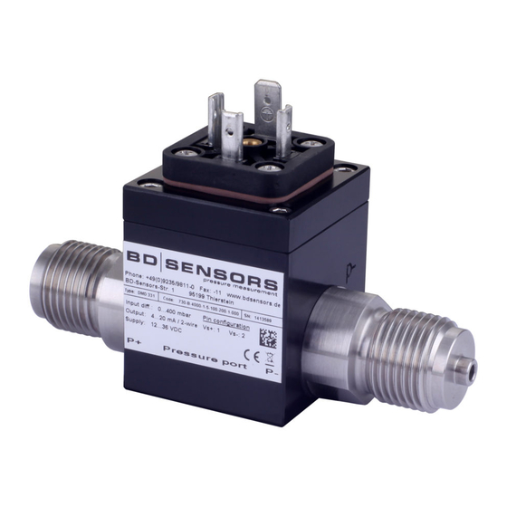
DMD 331
READ THOROUGHLY BEFORE USING THE DEVICE
KEEP FOR FUTURE REFERENCE
ID: BA_ DMD331_DMD341_E | version: 09.2019.0
1. General and safety-related information on
this operating manual
This operating manual enables safe and proper handling of the
product, and forms part of the device. It should be kept in close
proximity to the place of use, accessible for staff members at any
time.
All persons entrusted with the mounting, installation, putting into
service, operation, maintenance, removal from service, and
disposal of the device must have read and understood the
operating manual and in particular the safety-related information.
Complementary to this operating manual the current data sheet
has to be adhered to.
Download this by accessing www.bdsensors.de or request it by
e-mail or phone: info@bdsensors.de
phone: +49 (0) 92 35 / 98 11 0
In addition, the applicable accident prevention regulations, safety
requirements, and country-specific installation standards as well
as the accepted engineering standards must be observed.
1.1
Symbols used
-
Type and source of danger
-
Measures to avoid the danger
Warning word
Warning word
Meaning
-
Imminent danger!
-
Non-compliance will result in
DANGER
death or serious injury.
-
Possible danger!
-
Non-compliance may result in
WARNING
death or serious injury.
-
Hazardous situation!
-
Non-compliance may result in
CAUTION
minor or moderate injury.
NOTE
- draws attention to a possibly hazardous situation that
may result in property damage in case of non-compliance.
Precondition of an action
1.2 Staff qualification
Qualified persons are persons that are familiar with the
mounting, installation, putting into service, operation,
maintenance, removal from service, and disposal of the
product and have the appropriate qualification for their
activity.
This includes persons that meet at least one of the following
three requirements:
-
They know the safety concepts of measuring and
automation technology and are familiar therewith as
project staff.
-
They are operating staff of the measuring and
automation systems and have been instructed in the
handling of the systems. They are familiar with the
operation of the devices and technologies described
in this documentation.
-
They are commissioning specialists or are employed
in the service department and have completed
training that qualifies them for the repair of the
system. In addition, they are authorized to put into
operation, to ground, and to mark circuits and devices
according to the safety engineering standards.
All work with this product must be carried out by qualified
persons!
1.3 Intended use
The devices are used to convert the physical parameter of
pressure into an electric signal.
The differential pressure transmitter DMD 331 and DMD 341 are
intended for industrial applications. For both sided pressure
admission, the difference of the pressure between positive and
negative side is established and converted into a proportional
electrical signal. They are intended e.g. in engineering and plant
construction for filter controlling and flow measurement as well as
in hydraulic applications.
The user must check whether the device is suited for the selected
use. In case of doubt, please contact our sales department:
info@bdsensors.de | phone: +49 (0) 92 35 / 98 11 0
BD|SENSORS assumes no liability for any wrong selection and
the consequences thereof!
Permissible media for DMD 331 are gases and liquids or for
DMD 341 non-aggressive gases and pressured air are,
which are compatible with the media wetted parts described in
the data sheet.
The technical data listed in the current data sheet are engaging
and must absolutely be complied with. If the data sheet is not
available, please order or download it from our homepage:
http://www.bdsensors.de
Danger through incorrect use
- In order to avoid accidents, use the
device only in accordance with its
WARNING
intended use.
1.4 Limitation of liability and warranty
Failure to observe the instructions or technical regulations,
improper use and use not as intended, and alteration of or
damage to the device will result in the forfeiture of warranty and
liability claims.
1.5 Safe handling
NOTE -
Do not use any force when installing the device to
prevent damage of the device and the plant!
NOTE -
Treat the device with care both in the packed and
unpacked condition!
NOTE -
The device must not be altered or modified in any way.
NOTE -
Do not throw or drop the device!
NOTE -
Excessive dust accumulation (over 5 mm) and
complete coverage with dust must be prevented!
NOTE -
The device is state-of-the-art and is operationally
reliable. Residual hazards may originate from the device if it is
used or operated improperly.
1.6 Scope of delivery
Check that all parts listed in the scope of delivery are included
free of damage, and have been delivered according to your
purchase order:
- differential pressure transmitter
- mounting instructions
1.7 UL approval (for devices with UL marking)
The UL approval was effected by applying the US standards,
which also conform to the applicable Canadian standards on
safety.
Observe the following points so that the device meets the
requirements of the UL approval:
- The device must be operated via a supply with energy
limitation (acc. to UL 61010) or an NEC Class 2 energy supply.
- Maximum operating range: see data sheet
2. Product identification
The device can be identified by its manufacturing label. It
provides the most important data. By the ordering code the
product can be clearly identified.
Type designation
Ordering code
Serial number
Fig. 1: Example of manufacturing label
NOTE -
The manufacturing label may not be removed!
3. Mounting
3.1 Mounting and safety instructions
Danger of death from airborne parts,
leaking fluid, electric shock
-
Always mount the device in a
depressurized and de-energized
DANGER
condition!
Danger of death from improper
installation
-
Installation must be performed only by
appropriately qualified persons who
DANGER
have read and understood the user
manual.
NOTE
- Treat any unprotected diaphragm with utmost care; this
can be damaged very easily.
NOTE -
Provide for a cooling section if the device is used in a
steam line.
NOTE -
Do not mount the device in a pneumatic flow rate!
NOTE -
When installing the device, avoid high mechanical
stresses on the pressure port! This will result in a shift of the
characteristic curve or to damage, in particular in case of very
small pressure ranges and devices with pressure ports made of
plastic.
NOTE -
For the connection of the pressure lines, a sealing has
to be installed by the operator.
NOTE -
For the pipe assembly, a stress free installation must
be observed.
NOTE -
Consider for the installation of DMD 331 that the
pressure ports must not be turned against the housing!
NOTE -
Do not remove the packaging or protective caps of the
device until shortly before the mounting procedure, in order to
exclude any damage to the diaphragm and the threads!
Protective caps must be kept! Dispose of the packaging properly!
NOTE -
The specified tightening torques must not be exceeded!
NOTES -
for mounting outdoors or in a moist
environment:
- Please note that your application does not show a dew point,
which causes condensation and can damage the pressure
transmitter. There are specially protected pressure transmitters
for these operating conditions. Please contact us in such case.
- Connect the device electrically straightaway after mounting or
prevent moisture penetration, e.g. by a suitable protective cap.
(The ingress protection specified in the data sheet applies to
the connected device.)
- Select the mounting position such that splashed and
condensed water can drain off. Stationary liquid on sealing
surfaces must be excluded!
- For devices with cable socket, the outgoing cable must be
routed downwards. If the cable needs to be routed upwards,
this must be done in an initially downward curve.
- Mount the device such that it is protected from direct solar
radiation. In the most unfavourable case, direct solar radiation
leads to the exceeding of the permissible operating
temperature.
- If installing the device outdoor and there is any danger of
lightning or overpressure, we suggest putting an overpressure
protection unit between the supply / switch cabinet and the
device to prevent damage.
3.2 General mounting steps
1. Connect the reference pressures according to the following
installation steps. Therefore, keep in mind that
- the higher pressure has to be connected with input
"+" (DMD 331) or "P1" (DMD 341)
- lower pressure has to be connected with input
"-" (DMD 331) or "P2" (DMD 341)
2. Fix the device according to your demands on the holder or
holding angle intended for it. For mounting the device,
mounting threads (M4 – 10 deep) are provided.
For DMD 341, in addition, the possibility is given to mount
the device by using the two holes (Ø 4.5 mm).
The exact position is defined in the data sheet.
3.3 Installation steps for DMD 331
G 1/2" according to EN 837
The sealing surfaces are perfectly smooth and clean.
(R
6.3)
Z
For each pressure port a suitable cooper gaskets,
corresponding to the diameter of the threads which should
be screwed in, is used. (seals are not included in the scope
of delivery)
1
Screw the fittings into the threads by hand.
2
To tighten the fittings properly, hold the DMD 331 on the
spanner flat SW 22 of the respective pressure port with one
hand and then tighten it (max. 50 Nm).
G 1/4" internal thread
Suitable seals for the measured fluid and the pressure to be
measured are available.
The sealing surfaces of the fittings are perfectly smooth and
clean. (R
6.3)
Z
1
Screw the fittings into the threads by hand.
2
To tighten the fittings properly, hold the DMD 331 on the
spanner flat SW 22 of the respective pressure port with one
hand and then tighten it. The torque depends on the
counterpart (permissible tightening torque for the device is
20 Nm max).
G 7/16" UNF
The pressure ports of the differential pressure transmitter
are sealed in a way that is suitable for your application.
(seals are not included in the scope of delivery)
1
Screw your fittings by hand onto the threads.
2
To tighten the fittings properly, hold the DMD 331 on the
spanner flat SW 22 of the respective pressure port with one
hand and then tighten it (max. 30 Nm).
3.4 Installation steps for DMD 341
G 1/8" Internal thread
The pressure ports of the differential pressure transmitter
are sealed in a way that is suitable for your application.
(seals are not included in the scope of delivery)
1
Screw the fittings into the threads as far as possible.
2
Tighten the fittings properly (max. 10 Nm).
tube nozzle Ø 6.6 x 11
1
Slip your flexible tubes ( 6 mm) onto the tube nozzles as
far as possible.
4. Electrical Connection
4.1 Connection and Safety Instructions
Danger of death from electric shock
-
Always mount the device in a
depressurized and de-energized
condition!
- Operate the device only within the
DANGER
specification! (data sheet)
- Improper installation may result in
electric shock.
The supply corresponds to protection class III
(protective insulation).
NOTE -
for device with ISO 4400 plug and socket
-
Please note that the socket has to be mounted properly to
ensure the ingress protection mentioned in the data sheet.
Please check if the delivered seal is placed between plug
and cable socket. After connecting the cable fasten the
cable socket on the device by using the screw.
-
It must be ensured that the external diameter of the
used cable is within the allowed clamping range
(Ø 4 ... 6 mm). Moreover you have to ensure that it lies in
the cable gland firmly and cleftlessly!
NOTE -
Use a shielded and twisted multicore cable for the
electrical connection.
4.2 Electrical Installation
Establish the electrical connection of the device according to the
technical data shown on the manufacturing label, the following
table and the wiring diagram.
Pin configuration:
ISO 4400
M12x1 (4-pin)
Electrical connection
Supply +
1
Supply –
2
Signal + (only 3-wire)
3
ground pin
Shield
Brad Harrison
cable colour
Electrical connection
(IEC 60757)
Mini Change
Supply +
A
WH (white)
Supply –
B
BN (brown)
Signal + (only 3-wire)
GN (green)
-
GNYE
Shield
C
(green-yellow)
Wiring diagrams:
2-wire-system (current)
supply +
p
I
supply –
3-wire-system (current/voltage)
supply +
p
supply –
A / V
I/U
signal +
5. Commissioning
Danger of death from airborne parts,
leaking fluid, electric shock
-
Operate the device only within the
DANGER
specification! (according to data sheet)
The device has been installed properly
The device does not have any visible defect
The device is operated within the specification.
(see data sheet and EC type-examination certificate)
Please note that for starting up, the device has to be stressed by
pressure simultaneously at both pressure ports. Otherwise the
sensor could be damaged. For one-sided pressure admission, the
permissible static pressure (one-sided) must be attended. Please
take this out of the current data sheet.
6. Maintenance
Danger of death from airborne parts,
leaking fluids, electric shock
-
Always service the device in a
DANGER
depressurized and de-energized
condition!
Danger of injury from aggressive fluids
or pollutants
-
Depending on the measured medium,
this may constitute a danger to the
operator.
WARNING
-
Wear suitable protective clothing
e.g. gloves, safety goggles.
If necessary, clean the housing of the device using a moist cloth
and a non-aggressive cleaning solution.
The cleaning medium for the media wetted parts (pressure port /
diaphragm / seal) may be gases or liquids which are compatible
with the selected materials. Also observe the permissible
temperature range according to the data sheet.
Deposits or contamination may occur on the diaphragm /
pressure port in case of certain media. Depending on the quality
of the process, suitable maintenance intervals must be specified
by the operator. As part of this, regular checks must be carried
out regarding corrosion, damage to the diaphragm and signal
shift.
If the diaphragm is calcified, it is recommended to send the
device to BD SENSORS for decalcification. Please note the
chapter "Service/Repair" below.
NOTE
- Wrong cleaning or improper touch may cause an
irreparable damage on the diaphragm. Therefore, never use
pointed objects or pressured air for cleaning the diaphragm.
7. Troubleshooting
Danger of death from airborne parts,
leaking fluids, electric shock
-
If malfunctions cannot be resolved, put
the device out of service (proceed
DANGER
according to chapter 8 up to 10)
NOTE
- Improper action and opening can damage the device.
Therefore, repairs on the device may only be executed by the
manufacturer!
In case of malfunction, it must be checked whether the device
has been correctly installed mechanically and electrically. Use the
following table to analyse the cause and resolve the malfunction,
if possible.
Fault: no output signal
Possible cause
Fault detection / remedy
connected incorrectly
inspect the connection
line break
inspect of all line connections
inspect the ampere meter (fine-
defective ampere meter
wire fuse) or the analogue input
(signal input)
of the PLC
Fault: analogue output signal too low
Possible cause
Fault detection / remedy
verify the value of the load
load resistance too high
resistance
verify the output voltage of the
supply voltage too low
power supply
inspect the power supply and
defective energy supply
the applied supply voltage at the
device
Fault: shift of output signal
Possible cause
Fault detection / remedy
recommendation: send the
1
diaphragm is contaminated or
device to BD SENSORS for
2
damaged
service / repair
3
Fault: wrong or no output signal
4
Possible cause
Fault detection / remedy
electrical connection is
check the connections
damaged
ensure that the higher
reverse polarity of the pressure
pressure has to be connected
ranges
with input "p+" (DMD 331) or
"P1" (DMD 341)
A
V
S
V
S
Advertisement

Related Manuals for BD Sensors DMD 331


Summary of Contents for BD Sensors DMD 331
- Page 1 The device is operated within the specification. 1.7 UL approval (for devices with UL marking) To tighten the fittings properly, hold the DMD 331 on the 1. General and safety-related information on (see data sheet and EC type-examination certificate)
- Page 2 8. Removal from Service Notes: Danger of death from airborne parts, ___________________________________________________________________________________________________ leaking fluids, electric shock ___________________________________________________________________________________________________ Disassemble the device in a depressurized and de-energized DANGER ___________________________________________________________________________________________________ condition! Danger of injury from aggressive ___________________________________________________________________________________________________ media or pollutants ___________________________________________________________________________________________________ - Depending on the measured medium, this may constitute a danger to the ___________________________________________________________________________________________________ operator.