Table of Contents
Advertisement
Quick Links
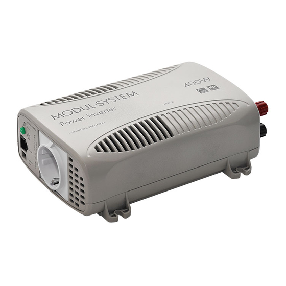
True Sinewave Power Inverter
21040-03
Owner's Manual
For safe and optimum performance, the Power Inverter must be used properly. Carefully read
and follow all instructions and guidelines in this manual and give special attention to the
CAUTION and WARNING statements.
PLEASE KEEP THIS MANUAL FOR FUTURE REFERENCE
Disclaimer
While every precaution has been taken to ensure the accuracy of the contents of this guide,
Modul-System assumes no responsibility for errors or omissions. Note as well that
specifications and product functionality may change without notice.
Important
Please be sure to read and save the entire manual before using your Modul-System Power
Inverter. Misuse may result in damage to the unit and/or cause harm or serious injury. Read
the manual in its entirety before using the unit and save the manual for future reference.
True Sinewave Series:
21040-03
12V 400W 230VAC True Sinewave Inverter
P/N: MSIN400W Rev 1.3
Service Contact Information
Email: info@modul-system.com
Phone:
+46 31 746 87 00
Web:
www.modul-system.com
1. INTRODUCTION
Thank you for purchasing the Modul-System Power Inverter. With our state of the art, easy to
use design, this product will offer you reliable service for providing AC power for your vehicle,
trailer or container. The Modul-System Power Inverter can run many AC-powered appliances
when you need AC power anywhere.
This manual will explain how to use this unit safely and effectively. Please read and follow
these instructions and precautions carefully.
IMPORTANT SAFETY INFORMATION
This section contains important safety information for the Modul-System Power Inverter. Each
time, before using the Modul-System Power Inverter, READ ALL instructions and cautionary
markings on or provided with the inverter, and all appropriate sections of this guide.
The Modul-System Power Inverter contains no user-serviceable parts. See Warranty section
for how to handle product issues.
WARNING: Fire and/or chemical burn hazard
• Do not cover or obstruct any air vent openings and/or install in a zero-clearance compartment.
WARNING: Failure to follow these instructions can result in death or series injury
• When working with electrical equipment or lead acid batteries, have someone nearby in case
of an emergency.
• Study and follow all the battery manufacturer's specific precautions when installing, using
and servicing the battery connected to the inverter.
• Wear eye protection and gloves.
• Avoid touching your eyes while using this unit.
• Keep fresh water and soap on hand in the event battery acid comes in contact with eyes. If
this occurs, cleanse right away with soap and water for a minimum of 15 minutes and seek
medical attention.
• Batteries produce explosive gases. DO NOT smoke or have an open spark or fire near the
system.
• Keep unit away from moist or damp areas.
• Avoid dropping any metal tool or object on the battery. Doing so could create a spark or
short circuit which goes through the battery or another electrical tool that may create an
explosion.
WARNING: Shock Hazard. Keep away from children!
• Avoid moisture. Never expose unit to snow, water etc.
.
• Unit provides household AC, treat AC output sockets the same as regular wall AC sockets at
home.
WARNING: Explosion hazard!
• DO NOT use the Modul-System Power Inverter in the vicinity of flammable fumes or gases
(such as propane tanks or large engines).
• AVOID covering the ventilation openings. Always operate unit in an open area.
EMC INFORMATION
This equipment has been tested and found to comply with the limits for CE EMC standard.
These limits are designed to provide reasonable protection against harmful interference in a
residential installation. This equipment generates, uses and can radiate radio frequency
energy and, if not installed and used in accordance with the instructions, may cause harmful
interference to radio communications. However, there is no guarantee that interference will not
occur in a particular installation. If this equipment does cause harmful interference to radio or
television reception, which can be determined by turning the equipment off and on, the user is
encouraged to try to correct the interference by one or more of the following measures:
• Re-orient or relocate the receiving antenna.
• Increase the separation between the equipment and the receiver.
• Connect the equipment into an outlet on a circuit different from that to which the receiver is
connected.
• Consult the dealer or an experienced radio/TV technician for help.
LIMITATIONS ON USE
Do not use in connection with life support systems or other medical equipment or devices.
2. PRODUCT DESCRIPTION
The Modul-System Power Inverter package includes the items list below.
(Schuko - CEE 7/4)
• Power Inverter base unit
• Owner's manual
• Cable boots
• Lighter plug cable
• Battery clips cable
3. INSTALLATION
WARNING: Modul-System recommends that all wiring be done by a certified technician or
electrician to ensure adherence to the applicable electrical safety wiring regulations and
installation codes. Failure to follow these instructions can damage the unit and could also
result in personal injury or loss of life.
CAUTION: Before beginning your power inverter Installation, please consider the following:
• The Power Inverter base unit should be used or stored in an indoor area away from direct
sunlight, heat, moisture or conductive contaminants.
• When placing the unit, allow a minimum of 80 mm of space around the unit for optimal
ventilation.
Understanding the unit features
Installation Preparation
Typical wiring block diagram of the Power Inverter:
Battery Bank:
• The use of deep cycle battery is highly recommended for power inverter application
• For battery size, you need to identify how long you wish to operate the load(s). Modul-
System does recommend that you purchase as much battery capacity as
minimum of 40AH.
See more on "Estimated Run time and Load" in Section 4.
• Please use 12V Battery Bank system for the 21040-03 Power inverter. Using 24V or higher
voltage Battery Bank System will damage the inverter and may cause fire.
Fuse or Circuit Breaker:
• DC-rated fuse or DC-rated circuit breaker connected along the DC positive line is required.
• Select a fuse or circuit breaker with 40A minimum rating.
• Based on the size of the battery bank chosen on the 12V system above, determine the
overall short circuit current rating of the battery bank from the battery manufacturer. The
fuse or circuit breaker chosen has to be able to withstand the short circuit current that may
be generated by the battery bank.
Disconnect Switch:
• Select a Disconnect Switch with the same or higher rating of the selected fuse or circuit
breaker from the above.
• The Disconnect Switch is used to disconnect the DC power between the power inverter
and the battery bank during service, maintenance or trouble shooting.
Installing the Power Inverter System
WARNING: Electrical Shock Hazard
The unit green 'On/Off' switch does not disconnect the DC power from the battery. Use the DC
Disconnect Switch or disconnect the DC input cables connection to disconnect the DC power
from the battery before working on any circuits connected to the unit. Failure to follow these
instructions can result in death or serious injury.
CAUTION: Unit Damage
Reversing the battery connection to the DC Input terminals will damage the unit and it cannot
be repaired. Damage caused by reverse polarity connection is not covered by the warranty.
Power Inverter Installation
Using the provided Accessories for temporary use
Lighter Plug Cable:
CAUTION: Due to the limitations of the 12V lighter plug socket in vehicles, the unit should be
used with the DC cable with lighter plug only to supply AC power to products that require
150W (120VAC/1.3A or 230V/0.65A) or less. If the appliance requires more than 150W, use
the DC Battery Clips Cable for battery connection.
• Attach the red ring-type connector to the positive (+) DC terminal (red) on the power
inverter and connect the black ring type connector to the negative (-) DC terminal (black)
on the Power inverter.
• Tighten the nut on each DC terminal.
• Insert the lighter plug of this cable to the fused 12V lighter plug socket.
• Unit is ready for use.
Battery Clips Cable:
CAUTION: Please be sure all the connections are tight before the use of the unit.
• Attach the red ring-type connector to the positive (+) DC terminal (red) on the power
inverter and connect the black ring type connector to the negative (-) DC terminal (black)
on the Power inverter.
• Attach the negative (black) clip to the negative (-) battery terminal.
• Attach the positive (red) clip to the fuse or circuit breaker of the 12V battery bank as
indicated on 'Installation Preparation' diagram.
• Unit is ready for use.
possible, with a
Advertisement
Table of Contents

Related Manuals for Modul-System True Sinewave Series


Summary of Contents for Modul-System True Sinewave Series
- Page 1 1. INTRODUCTION Understanding the unit features Thank you for purchasing the Modul-System Power Inverter. With our state of the art, easy to use design, this product will offer you reliable service for providing AC power for your vehicle, trailer or container. The Modul-System Power Inverter can run many AC-powered appliances when you need AC power anywhere.
- Page 2 Small Freezer (8.8 cu. ft.) 15 hrs • The Power On/Off push button on the remote shares the same function as the green department at info@modul-system.com or phone +46 31 746 87 00 before returning product. 20” LCD TV 100W 11.5 hrs...
Need help?
Do you have a question about the True Sinewave Series and is the answer not in the manual?
Questions and answers