Advertisement
AP141 5-GH
I
NSTALLATION
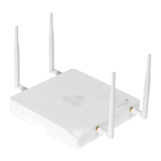
This guide explains how to install an Aerohive AP141 5-GHz directional point-to-point antenna and connect it
to an AP141 access point. The AH-ACC-141-ANT-5 (MARS part number M300310400015) is an indoor
dual-band lightweight antenna that is well suited for applications where a 120° H-plane and a 70° E-plane
are optimal. These antennas are typically corner-mounted in pairs, facing each other and with no
obstructions between them..
For the latest product documentation, compliance information, and software updates, visit
www.aerohive.com/support.
K
C
, R
IT
ONTENTS
EQUIRED
The AP141 5-GHz directional antenna kit includes the following items:
•
AP141 5-GHz 5-dBi antenna (Aerohive part number AH-ACC-141-ANT-5, MARS part number
M300310400015)
•
(4)1.25" x 1/8" (32 mm x 3 mm) cross-head screws
•
(4) 1.25"" (32mm) drywall and concrete wall anchors
To install this antenna, you will need the following accessories and tools:
•
Cross-head screwdriver, drill with a 1/8" (32mm) bit, and hammer
•
RF test meter for 5-GHz devices
S
I
AFETY
NSTRUCTIONS AND
Read and follow these safety instructions and hazard warnings before installing this antenna. Keep these
instructions for future reference.
To comply with radio frequency exposure limits, do not place this antenna within 26" (65 cm) of
people.
To install this antenna, you must be a qualified installation professional, licensed or certified in
accordance with local regulations.
Use only attachments and accessories specified by Aerohive.
Do not locate the antenna near overhead power lines or other electric light or power circuits, or
where it can come into contact with such circuits. During installation, exercise extreme care not to
come into contact with these circuits, which can cause serious injury or death. For proper installation
of the product, refer to national and local electrical codes: NFPA (National Fire Protection
Association) 70, National Electrical Code Article 810 (U.S.); Canadian Electrical Code, Part I, CSA 22.1
and Section 54 (Canada); and if local or national electrical codes are not available, refer to IEC
(International Electrotechnical Commission) 364, Part 1 through 7 (other countries).
Do not connect or disconnect antennas or cables from the AP141 during periods of lightning activity.
© 2012 Aerohive Networks, Inc.
All rights reserved.
P/N 330089-01
D
Z
IRECTIONAL
G
UIDE
A
CCESSORIES
S
H
ITE
AZARD
A
NTENNA
,
T
AND
OOLS
W
ARNINGS
1
Advertisement
Table of Contents

Related Manuals for Aerohive Networks AP141


Summary of Contents for Aerohive Networks AP141
- Page 1 NSTALLATION UIDE This guide explains how to install an Aerohive AP141 5-GHz directional point-to-point antenna and connect it to an AP141 access point. The AH-ACC-141-ANT-5 (MARS part number M300310400015) is an indoor dual-band lightweight antenna that is well suited for applications where a 120° H-plane and a 70° E-plane are optimal.
- Page 2 IRECTIONAL NTENNA To provide unobstructed RF coverage, mount the AP141 antenna so that it has at least a three-foot (one-meter) clearance from any nearby obstructions. For best coverage, these antennas are typically installed in pairs, directly facing each other, and with no obstructions between them.
- Page 3 Connecting the Antenna to the AP141 Connect the antenna cables to the 5-GHz jacks on the AP141, as shown in the illustration below. You can use 2.4 GHz antennas in addition to the 5-GHz directional antenna. Always install a 50-Ohm load terminator on any unused antenna connector.
- Page 4 AP141 5-GHz Directional Antenna Installation Guide...
Need help?
Do you have a question about the AP141 and is the answer not in the manual?
Questions and answers