
Related Manuals for Brasch GDCP-Touch

Summary of Contents for Brasch GDCP-Touch
- Page 1 GDCP-Touch Installation / Operation Manual Brasch Environmental Technologies, LLC 140 Long Road, Suite 101 Chesterfield, Missouri 63005 314-291-0440 www.braschenvtech.com...
-
Page 2: Table Of Contents
Table of Contents Introduction...........................5 General Description........................5 Features and Benefits......................6 Technical Specifications........................7 Product Specifications......................7 Target Gas Specifications......................8 Carbon Monoxide.........................8 Nitrogen Dioxide........................8 Operation Safety Notice........................9 Types of Notices........................9 Quick Start Guide........................10 Step 1 – Mounting........................10 Step 2 – Input Wiring......................10 Step 3 – Remote Transmitter Wiring..................11 Step 4 –... - Page 3 Relay Screen........................26 Passcode Entry Screen......................27 Settings Menu........................27 Factory Default Settings......................28 Adjusting the Hardware Settings....................29 Changing the Sensor Address...................29 Changing the Relay Board Address...................29 Changing the Analog Output Scale..................29 Adjusting the Software Settings.....................30 Adding/Removing Sensors....................30 Adding/Removing Relays....................30 Adding/Removing Zones....................31 Adjusting the Setpoints......................31 Adjusting the Delays......................32 Adjusting the Activation Type.....................32 Adjusting the Zone Display Type..................33...
- Page 4 Checking and Replacing Fuses....................46 Common Installation/Operation Mistakes................47 Ventilation Components Connected to the Wrong Relays..........47 Relay Levels Set Incorrectly....................47 Improper Communication Wiring..................47 Setpoint Level Set at Wrong Concentration...............47 Delay Period Set Incorrectly....................48 Setting the Proportional Output Incorrectly................48 Bias/Termination Switches in the Wrong Position..............48 Relay Activation Type Set Incorrectly.................49 Panel Not Grounded......................49 Transmitter Mounted in an Unsatisfactory Location............49...
-
Page 5: Introduction
The GDCP-Touch housing has a NEMA 4X rating and is supplied with knockouts so that the control panel can mount directly to a standard four inch conduit box. A hinged cover secured by two screws makes it easy to gain access to the touchscreen for system configuration. -
Page 6: Features And Benefits
Features and Benefits • Limitless Possibilities ◦ Fully Configurable Zones, Relays, Setpoints, Delays, and Outputs ◦ Scalable System Size via Relay Expansion Packs • Increased Control ◦ On-Demand Ventilation Control by Gas Concentration, Timer Schedule, or User Input ◦ 7” Full-Color LCD Touch Screen •... -
Page 7: Technical Specifications
Technical Specifications Product Specifications Input Power 24 VAC, 50/60 Hz, 0.75 A Optional: 120 VAC, 50/60 Hz, 0.3 A via GDCP-PowerPack Installation Category II (local level, over-voltage transients less than 500V) Storage Temperature -50°C to 120°C (-58°F to 248°F) Operating Temperature -20°C to 70°C (-4°F to 158°F) Humidity 10% to 90% (non-condensing) -
Page 8: Target Gas Specifications
Brasch Environmental Technologies, LLC has designed their transmitters so that the measurement ranges for each target gas meet the agencies’ requirements. Each target gas, for which Brasch currently produces a transmitter, is listed below along with the relevant concentration specifications. -
Page 9: Operation Safety Notice
Operation Safety Notice Certain procedures and operations detailed in this manual require that specific precautions be taken prior to beginning the procedure or operation. When precautions are required, a notice will be printed in an appropriate location in the manual. The user is urged to read and understand all such notices. -
Page 10: Quick Start Guide
Contact Brasch Environmental Technologies, LLC before connecting power to the control panel or transmitters if you are unsure of the correct power requirement. -
Page 11: Step 3 - Remote Transmitter Wiring
Connect the incoming power conductor to 18-24VAC, the return conductor to 18-24RET, and the ground conductor to the green screw. Refer to page 15 for further information. Step 3 – Remote Transmitter Wiring The control panel does not supply power to the remote transmitters. However, power may be daisy chained through the control panel to the transmitters. -
Page 12: Step 5 - External Alarms
silkscreen next to the terminal blocks as well as in the diagram on page 54. The relay state is labeled for the physical state of the relay when the control panel is not powered. In the default configuration, all relays will operate independently of one another. To use multiple-speed fans, you will need to assign different relay levels in the settings and invert the wiring connections to avoid damaging ventilation equipment. -
Page 13: Installation
Installation Mounting the Control Panel The control panel is the central hub for monitoring and controlling all of the transmitters. However, it does not necessarily need to be mounted in a centralized location. It should be mounted indoors in a dry location where authorized users will have easy access and the display can be easily read. - Page 14 • Do not locate any transmitter further than 4000 feet from a control panel or expansion pack. • The types of gases each unit is designed to monitor have densities approximately equal to that of air. For maximum safety, mount the unit at the average breathing height – approximately 5 to 7 feet from the floor.
-
Page 15: Connecting The Power Supply
surface with screws. Securely tighten the fitting nut on the inside of the conduit box so it will not loosen over time. • Attach the housing to a solid support base using screws through the internal housing mounting holes. This method requires removal of the housing cover to gain access to the mounting holes. -
Page 16: Connecting The Remote Transmitters
Contact Brasch Environmental Technologies, LLC before connecting power to the control panel and transmitters if you are unsure of the correct power requirement. -
Page 17: Connecting The Ventilation System
CAUTION It is very important that the power and signal connections between each transmitter and between the transmitters and the control panel be correct. If the connections are wired incorrectly, damage to both the transmitters and the control panel will occur. Use a cable with color-coded conductors and make sure that the same conductor connects to the same terminal on each transmitter and the control panel. -
Page 18: Connecting The External Alarm
Figures 1 and 2 on page 20 show typical alarm wiring. Connecting the Voltage or Current Proportional Output The GDCP-Touch and GDCP-ExpansionPack include circuits that provide either a current loop or voltage proportional output. Each output produces a linear response over the full scale range of the average of all connected sensors in a zone. -
Page 19: Performing A System Test
Performing a System Test The manual overrides on this control panel can be used to open and close the relays to verify that ventilation and warning equipment is connected properly. This feature can be accessed by navigating to Settings > Relay Settings> Relay #. Selecting “On” or “Off” will activate and deactivate the relays accordingly. -
Page 20: Typical Installation Diagrams
Typical Installation Diagrams Figure 1: Wiring – Two Fan Ventilation System with Common Alarm Figure 2: Wiring – Two-Speed Fan Ventilation System IOM03 Rev 1.1 – May 18, 2021... - Page 21 Figure 3: Wiring – Transmitter Connection – Daisy Chain (Dedicated Power) Figure 4: Wiring – Transmitter Connection – Daisy Chain (GDCP-PowerPack) IOM03 Rev 1.1 – May 18, 2021...
- Page 22 Figure 5: Wiring – Transmitter Connection – Star Configuration Figure 6: Wiring – Analog Output IOM03 Rev 1.1 – May 18, 2021...
-
Page 23: Operation
Sensor Map. Relays Every GDCP-Touch has four internal control relays with the option to add up to 32 total relays via GDCP-ExpansionPacks. The Relay Map tells the panel which relays to use for controlling equipment. -
Page 24: Zones
Analog Output Each GDCP-Touch and GDCP-ExpansionPack is equipped with one analog output that generates a 4-20 mA, 2-10 VDC, 1-5 VDC, or 0.2-1 VDC signal. This signal is proportional to the average concentration of target gas present in the assigned zone. It may be used for monitoring gas or for controlling a VFD. -
Page 25: Navigating The User Interface
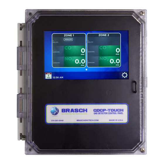
Navigating the User Interface Home Screen The Home Screen is where the control panel will be most of the time. This page is the central hub for displaying all of the information available on the panel. While not interacting with the panel, the Home Screen will automatically scroll through each configured zone. -
Page 26: Zone Screen
Zone Screen The Zone Screen gives more information about a zone. Here, the user can see each relay configured to that zone and each sensor configured to that relay. Sensor icons will display the current gas concentration value. As with the Home Screen, the zone concentration values will change colors depending on the setpoints. -
Page 27: Passcode Entry Screen
Passcode Entry Screen Upon pressing the “Settings” icon, the user will be asked for a passcode. This passcode is assigned at the factory and included in the packaging with every order. Entering the passcode will allow the user to make changes to the system. After 5 minutes of inactivity, the panel will automatically return to the Home Screen and the passcode will need to be reentered. -
Page 28: Factory Default Settings
Factory Default Settings Unless otherwise specified on the order form, the following settings will be used to configure the control panel. Setting Default Sensors All Sensors Configured Relays 4 Relays Relay 1 (Low Alert) All Sensors On-Delay 1 minute Off-Delay 1 minute Setpoint 35 PPM CO / 1.0 PPM NO... -
Page 29: Adjusting The Hardware Settings
Each transmitter ordered will be assigned a number 1 through 128 as applicable, alternating between Carbon Monoxide and Nitrogen Dioxide. Transmitter numbering should not be changed without first consulting Brasch technical support. Adjusting the Hardware Settings Changing the Sensor Address The sensor address is set by SW1 on the right side of each sensor board using a binary counting system. -
Page 30: Adjusting The Software Settings
Adjusting the Software Settings Adding/Removing Sensors To configure the sensors, navigate to Settings > Sensor Map. Active sensors will appear in green while inactive sensors will appear in gray. Each sensor icon will also include the gas type and current value (if present). If a sensor is not communicating with the control panel, it will default to gas type “CO”. -
Page 31: Adding/Removing Zones
Adding/Removing Zones Only zones that are configured will appear on the Home Screen. To add a zone, go to Settings > Zone Settings and select “Add/Remove Zone”. Press “Add Zone” in the pop-up window. There must always be at least one zone present for the system to function. A maximum of 32 zones may be configured. -
Page 32: Adjusting The Delays
Adjusting the Delays On-delays and off-delays can be set for each relay to adjust the duration before energizing/de- energizing the contacts. Navigate to Settings > Relay Settings > Relay #. Then tap “Setpoint Delay” and use the arrows to adjust the values. If no delay is desired, set the delay time to “0:00”. -
Page 33: Adjusting The Zone Display Type
To adjust the activation type for a relay, go to Settings > Relay Settings > Relay # and select “Activation Type”. To adjust the activation type for a zone alarm, go to Settings > Zone Settings > Zone # and select “Alarm Settings”. Not all activation types will always be available. Adjusting the Zone Display Type The zone display controls what gas concentration values are shown on the Home Screen. -
Page 34: Assigning Relays
will only dissociate that sensor from the current relay. Any other assignments will remain in effect. Assigning Relays In order for a relay to display its information, it must be assigned to a zone. To assign a relay, go to Settings > Zone Settings > Zone #. Then tap “Add Relay to Zone”. This will bring up the Relay Map to display all currently configured relays. -
Page 35: Changing Relay Levels
go to Settings > Zone Settings > Zone # > Analog Output and select “None” from the pop-up window. Changing Relay Levels Relay levels are used to coordinate the operation of multiple relays on a single zone. Relays of the same level can remain engaged at the same time. Relays of a higher level will disengage relays of a lower level when engaging themselves. -
Page 36: Setting Manual Overrides
Setting Manual Overrides Each relay can be manually overridden to force it either on or off. To access these options, navigate to Settings > Relay Settings > Relay #. Under “Relay Override Status”, selecting “On” will open a pop-up window to force the relay into its active state – as if its setpoint was exceeded. -
Page 37: Setting Automatic Overrides
Setting Automatic Overrides Each relay can schedule up to four separate times for an automatic override. Of these times, three may be used to force the relay into an active state while one may be used to force it into an inactive state. -
Page 38: Configuring Bacnet
Should too many changes be made that cause the panel to operate in an undesirable manner, Two options are available to reset the GDCP-Touch under Settings > Reset Options. “Reset to Default” will erase any custom sensor, relay, or zone settings while leaving all assignments intact. -
Page 39: Using The Analog Outputs
21 on page 59 of this manual. As an example, a Brasch Carbon Monoxide Transmitter has a full scale output of 200 PPM CO. For the 4-20 mA output mode with a single sensor configured, 0 PPM CO would equal 4 mA while 200 PPM CO would equal 20 mA. -
Page 40: Obtaining The Best Operation
Obtaining the Best Operation Carbon Monoxide and/or Nitrogen Dioxide Transmitters This panel is designed to control the ventilation system in response to a rising concentration of the target gas at its transmitters. No two installations will be exactly the same. Different ventilation components, the number of gas producing sources, air flow patterns inside the room, the total room volume, and the exact location of the transmitters influence how effective the system is in controlling the target gas concentration. -
Page 41: Maintenance
Maintenance Testing the Response to the Target Gas Carbon Monoxide and/or Nitrogen Dioxide Transmitters Testing these transmitters requires that the target gas be applied to the sensor using one of two methods. Gas can be applied from a tank of air containing a known concentration of the target gas or from the exhaust of an operating engine to produce a level of target gas sufficient to elicit a response from the control panel. -
Page 42: Replacing The Sensor
However, sufficient response can be obtained to determine that the transmitter is working. Brasch Environmental Technologies recommends testing the transmitters once every six months to ensure proper response and accuracy. Replacing the Sensor The sensor’s useful lifetime depends greatly upon its operating conditions. -
Page 43: Suggested Repair Parts
This control panel contains few field serviceable parts. However, the battery and fuses are replaceable in the field. While an open fuse may indicate problems with the circuitry, fuses may also open because of power surges or ventilation component failure. Brasch recommends that the following parts be available for replacement. -
Page 44: Troubleshooting
Troubleshooting Error Messages The GDCP-Touch is programmed to display error messages to indicate a problem condition with the unit. The bottom center of the Home Screen will scroll through each message present. When an error occurs, the alarm will chirp and a silence button will replace the calendar icon to allow a user to mute the alarm. -
Page 45: Sensor # Sensor Missing
When this error message appears, replace the sensor board. Sensor # Sensor Missing If no gas sensor is present on the sensor board, this error message will appear on the display. Verify that there is a sensor on the sensor board and that it is fully seated in its socket. If not, place the sensor firmly into the socket. -
Page 46: Checking And Replacing The Battery
The real-time clock circuitry is powered by a single CR1220 lithium-ion battery. This circuit is responsible for maintaining the date and time settings while the GDCP-Touch does not have power. If the date and time settings reset after a power cycle, the CR1220 battery may need to be replaced. -
Page 47: Common Installation/Operation Mistakes
Improper communication wiring, or exceeding the number of nodes on a single bus, can cause communication between the panel and transmitters to be inconsistent. The GDCP-Touch uses Modbus RTU over RS-485 for communication. All standard guidelines apply for this type of wiring. -
Page 48: Delay Period Set Incorrectly
concentration to that which produces the most efficient ventilation system operation while protecting people in the monitored area. Setting the concentration too high can create a situation in which the target gas concentration becomes dangerous, or the area contains too much smoke from engine exhaust. -
Page 49: Relay Activation Type Set Incorrectly
Brasch strongly recommends that the control panel be grounded according to applicable wiring codes. However, if this is not possible, using a stylus or otherwise ensuring that the touch input is at the same potential as the floating ground will improve touch accuracy and responsiveness. -
Page 50: Limited Warranty
If service or repair of your Brasch product becomes necessary, an authorization request for returning the product to the Brasch factory must be obtained from our sales office. If you are an end user, please contact your Brasch representative or distributor to initiate this request. -
Page 51: Appendix
Models and Descriptions Transmitter Model and Description Each Brasch Gas Transmitter is given a model that describes the type(s) of target gas(es). This model appears on the front panel label. Use the following list to completely identify a transmitter once you know the model. -
Page 52: Figures And Diagrams
Figures and Diagrams Figure 7: Home Screen Layout – Normal Figure 8: Home Screen Layout – Alarm IOM03 Rev 1.1 – May 18, 2021... - Page 53 Figure 9: Transmitter Front Cover Layout Black +UNREG White Black -UNREG Blue -COMM Brown +COMM Figure 10: Transmitter Wiring Connections IOM03 Rev 1.1 – May 18, 2021...
- Page 54 4-20 mA JP2 JP3 2-10 VDC JP2 JP3 1-5 VDC JP2 JP3 0.2-1 VDC JP2 JP3 Figure 11: Transmitter Proportional Output Settings Sensor 1 Sensor 2 Sensor 3 Sensor 4 Figure 12: Sensor Address Assignment IOM03 Rev 1.1 – May 18, 2021...
- Page 55 Sensor Switch Sensor Switch Sensor Switch Sensor Switch Address Position Address Position Address Position Address Position 0000000 0100000 1000000 1100000 0000001 0100001 1000001 1100001 0000010 0100010 1000010 1100010 0000011 0100011 1000011 1100011 0000100 0100100 1000100 1100100 0000101 0100101 1000101 1100101 0000110 0100110 1000110...
- Page 56 Relay Wiring (TS3-TS6) Figure 14: Relay Contact Connections AC Input Wiring (TS1 & TS2) Figure 15: Input Power Connections IOM03 Rev 1.1 – May 18, 2021...
- Page 57 -COMM +COMM ISO GND Isolated COMM (TS7) Figure 16: Transmitter Connection – Input Non-isolated COMM (TS8 & TS11) Figure 17: Transmitter Connection – Output IOM03 Rev 1.1 – May 18, 2021...
- Page 58 Relay Board # Figure 18: Relay Board Address Assignment Isolated Resistors Non-isolated Resistors Figure 19: Relay Board Bias/Termination Resistors IOM03 Rev 1.1 – May 18, 2021...
- Page 59 2-10 VDC 1-5 VDC 0.2-1 VDC 4-20 mA Figure 20: Analog Output Settings Carbon Monoxide Output (mA) Nitrogen Dioxide Output (mA) Figure 21: Analog Output Graphs (4-20 mA) IOM03 Rev 1.1 – May 18, 2021...
- Page 60 Figure 22: Mounting Dimensions (Not to Scale) IOM03 Rev 1.1 – May 18, 2021...
- Page 61 Figure 23: Control Panel Assembly – Exploded Inside View IOM03 Rev 1.1 – May 18, 2021...
- Page 62 Figure 24: Control Panel Assembly - Exploded Outside View IOM03 Rev 1.1 – May 18, 2021...
- Page 63 The above figures are not complete lists of all possible desensitizing or contaminating gases or substances. Take caution to evaluate the probable effect of a contaminant not included in the above list. Contact Brasch Environmental Technologies technical support to learn more. IOM03...
- Page 64 Website: www.braschenvtech.com Technical Support Contact Information Phone: 314-291-0440 ext. 1006 Fax: 314-291-0646 Email: customerservice@braschenvtech.com Website: www.braschenvtech.com/support-for-existing-systems Revision: 1.1 Issue Date: May 18, 2021 Document Number: IOM03 © Brasch Environmental Technologies, LLC All Rights Reserved IOM03 Rev 1.1 – May 18, 2021...
Need help?
Do you have a question about the GDCP-Touch and is the answer not in the manual?
Questions and answers