Table of Contents
Advertisement
Quick Links
2/22/2018
DYNAMIXEL
PLATFORM
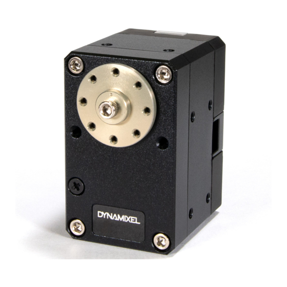
XM430-W210
1. Specifications [+]
2. Control Table [+]
3. How to Assemble [+]
4. Maintenance [+]
5. Reference [+]
Back to Top ▲
http://emanual.robotis.com/docs/en/dxl/x/xm430-w210/
ROBOTIS e-Manual
STEAM
SOFTWARE
XM430-W210
1. Specifications
Item
MCU
Position Sensor
Motor
Baud Rate
Control
Algorithm
Degree of
Precision
Operating
Modes
Weight
Dimensions (W x
H x D)
Gear Ratio
Stall Torque
Custom Search
PARTS
FAQ
Specifications
ST CORTEX-M3 (STM32F103C8 @ 72Mhz, 32Bit)
Contactless absolute encoder (12Bit, 360°)
Maker : ams(www.ams.com), Part No : AS5045
Coreless Motor
9600 bps ~ 4.5 Mbps
PID control
0.088°
Current Control Mode
Velocity Control Mode
Position Control Mode (0° ~ 360°)
Extended Position Control Mode
Current-based Position Control Mode
PWM Control Mode (Voltage Control Mode)
82g
28.5mm x 46.5mm x 34mm
212.6 : 1
2.7N.m @ 11.1V, 2.1A
3.0Nm @ 12.0V, 2.3A
3.7Nm @ 14.8V, 2.7A
Edit on GitHub
1/34
Advertisement
Table of Contents

Subscribe to Our Youtube Channel
Related Manuals for Robotis DYNAMIXEL XM430-W210

Summary of Contents for Robotis DYNAMIXEL XM430-W210
- Page 1 2/22/2018 ROBOTIS e-Manual Custom Search DYNAMIXEL PLATFORM STEAM SOFTWARE PARTS XM430-W210 Edit on GitHub 1. Specifications [+] 2. Control Table [+] 3. How to Assemble [+] 4. Maintenance [+] 5. Reference [+] Back to Top ▲ XM430-W210 1. Specifications...
-
Page 2: Performance Graph
2/22/2018 ROBOTIS e-Manual Item Specifications 70rpm @ 11.1V No Load Speed 77rpm @ 12.0V 95rpm @ 14.8V XM430-W210 Operating -5°C ~ +80°C Temperature Input Voltage 10.0 ~ 14.8V (Recommended : 12.0V) Standby Current 40mA Command Digital Packet Signal Back to Top ▲... -
Page 3: Control Table
2/22/2018 ROBOTIS e-Manual When connecting to power supply, it is recommended Caution using ROBOTIS controller or SMPS2DYNAMIXEL. Do not connect or disconnect DYNAMIXEL when power is being supplied. XM430-W210 2. Control Table The Control Table is a structure of data implemented in the DYNAMIXEL. - Page 4 2/22/2018 ROBOTIS e-Manual stands for read only access permission. Data with the read only property cannot be changed by the WRITE Instruction. Read only property(‘R’) is generally used for measuring and monitoring purpose, and read write property(‘RW’) is used for controlling DYNAMIXEL.
- Page 5 2/22/2018 ROBOTIS e-Manual Size Initial Address Data Name Description Access (Byte) Value Minimum Input Min Voltage Limit Voltage Limit Maximum PWM XM430-W210 PWM Limit Limit Maximum Current Current Limit 1193 Limit Maximum Acceleration Limit 32767 Accleration Limit Back to Top ▲...
- Page 6 2/22/2018 ROBOTIS e-Manual Size Initial Address Data Name Description Access (Byte) Value Feedforward 2nd Gain of Feed- 2nd Gain Forward Feedforward 1st Gain of Feed- XM430-W210 1st Gain Forward DYNAMIXEL Bus Watchdog Watchdog Goal PWM Target PWM Value Goal Current Target Current Value Back to Top ▲...
- Page 7 2/22/2018 ROBOTIS e-Manual Size Initial Address Data Name Description Access (Byte) Value Indirect Indirect Address 3 Address 3 … … … … … … XM430-W210 Indirect Indirect Address 26 Address 26 Indirect Indirect Address 27 Address 27 Indirect Indirect Address 28 Back to Top ▲...
-
Page 8: Firmware Version
2/22/2018 ROBOTIS e-Manual Size Initial Address Data Name Description Access (Byte) Value Indirect Data Indirect Data 31 … … … … … … XM430-W210 Indirect Data Indirect Data 54 Indirect Data Indirect Data 55 Indirect Data Indirect Data 56 Back to Top ▲... -
Page 9: Drive Mode
2/22/2018 ROBOTIS e-Manual Value Baud Rate Margin of Error 4.5M 0.000% 0.000% 0.000% XM430-W210 0.000% 0.000% 115,200 0.000% 1(Default) 57,600 0.000% Back to Top ▲ 9,600 0.000% Less than 3% of the baud rate error margin will not affect Note to UART communication. - Page 10 2/22/2018 ROBOTIS e-Manual Operating Value Description Mode DYNAMIXEL only controls current(torque) regardless of speed and position. This mode Current is ideal for a gripper or a system that only Control XM430-W210 uses current(torque) control or a system Mode that has additional velocity/position controllers.
- Page 11 2/22/2018 ROBOTIS e-Manual PWM is the abbreviation for Pulse Width Modulation that Note modulates PWM Duty to control motors. The PWM Control Mode changes pulse width to control average supply voltage to the motor and this technique is widely used in the motor control field.
- Page 12 2/22/2018 ROBOTIS e-Manual 2. 4. 9. Protocol Version(13) Users can select Dynamixel protocol version (1.0 and 2.0). It is recommended to use an identical protocol version for multiple Dynamixels. XM430-W210 Protocol Value Compatible Dynamixels Version AX Series, DX Series, RX Series, EX Series, MX...
- Page 13 2/22/2018 ROBOTIS e-Manual This value limits operating temperature. When the Present Temperature(146) that indicates internal temperature of Dynamixel is greater than the Temperature Limit(31), the Over Heating Error Bit(0x04) and Hardware Error Bit(0x80) in the Hardware Error Status(70) will be set.
- Page 14 2/22/2018 ROBOTIS e-Manual This value indicates maximum current(torque) output limit. Goal Current(102) can’t be configured with any values exceeding Current Limit(38). The Current Limit(38) is used in Torque Control Mode and Current-based Position Control Mode, therefore decreasing Current Limit(38) will result in XM430-W210 decreasing torque of DYNAMIXEL.
- Page 15 2/22/2018 ROBOTIS e-Manual Unit Value Range 0.088° 0 ~ 4,095(1 rotation) Max Position Limit(48) and Min Position Limit(52) are only Note used in Position Control Mode with a single turn. XM430-W210 2. 4. 19. Shutdown(63) The Dynamixel can protect itself by detecting dangerous situations that could occur during the operation.
- Page 16 2/22/2018 ROBOTIS e-Manual Manual.) If Shutdown occurs, LED will flicker every second.(Firmware v41 or above) XM430-W210 2. 4. 20. Torque Enable(64) Controls Torque ON/OFF. Writing ‘1’ to this address will turn on the Torque and all Data in the EEPROM area will be protected.
- Page 17 2/22/2018 ROBOTIS e-Manual 2. 4. 23. Registered Instruction(69) Value Description REG_WRITE instruction is not received REG_WRITE instruction is received XM430-W210 If ACTION instruction is executed, the value will be changed Note to 0. 2. 4. 24. Hardware Error Status(70) This value indicates hardware error status. The Dynamixel can Back to Top ▲...
- Page 18 2/22/2018 ROBOTIS e-Manual If Shutdown occurs, use below method to reboot Note Dynamixels. 1. H/W REBOOT : Turn off the power and turn on again 2. S/W REBOOT : Transmit REBOOT Instruction (For more XM430-W210 details, please refer to the [Reboot] section of Protocol e- Manual.)
- Page 19 2/22/2018 ROBOTIS e-Manual XM430-W210 stands for Anti-windup Gain and ‘β’ is a conversion Note coefficient of position and velocity that cannot be modified by users. For more details about the PID controller, please refer to Back to Top ▲ PID Controller at wikipedia.
- Page 20 2/22/2018 ROBOTIS e-Manual 2. Goal Position(116) is converted to target position trajectory and target velocity trajectory by Profile Velocity(112) and Profile Acceleration(108). 3. The target position trajectory and target velocity trajectory is stored at Position Trajectory(140) and Velocity XM430-W210 Trajectory(136) respectively.
- Page 21 2/22/2018 ROBOTIS e-Manual 4. Goal PWM(100) sets a limit on the calculated PWM output and decides the final PWM value. 5. The final PWM value is applied to the motor through an Inverter, and the horn of DYNAMIXEL is driven.
- Page 22 2/22/2018 ROBOTIS e-Manual packet. If the value of Bus Watchdog (98) is changed to ‘0’, Bus Watchdog Error will be cleared. For details of Range Error, please refer to the protocol of Note the e-Manual. XM430-W210 The following are examples of the operation of the Bus Watchdog function.
- Page 23 2/22/2018 ROBOTIS e-Manual Unit Value Range about 2.69[mA] -Current Limit(38) ~ Current Limit(38) Applying high current to the motor for long period of time Note might damage the motor. XM430-W210 2. 4. 30. Goal Velocity(104) In case of Velocity Control Mode, Goal Velocity(104) can be used to set a target velocity.
- Page 24 2/22/2018 ROBOTIS e-Manual Unit Value Range Description 0.229 rpm 0 ~ Velocity Limit(44) ‘0’ stands for an infinite velocity The Profile is an acceleration/deceleration control method to reduce vibration, noise and load of the motor by controlling XM430-W210 dramatically changing velocity and acceleration.
- Page 25 2/22/2018 ROBOTIS e-Manual distance difference between target position and current position). 4. Selected Profile type is stored at Moving Status(123).(Refer to the Moving Status(123)) 5. Dynamixel is driven by the calculated target trajectory from XM430-W210 Profile. 6. Target velocity trajectory and target position trajectory from Profile are stored at Velocity Trajectory(136) and Position Trajectory(140) respectively.
- Page 26 2/22/2018 ROBOTIS e-Manual be calculated as below equation. = 64 * {Goal Velocity(104) / Profile Acceleration(108)} 2. 4. 33. Goal Position(116) Target position can be set with Goal Position(116). From the XM430-W210 front view of Dynamixels, CCW is an increasing direction whereas CW is a decreasing direction.
- Page 27 2/22/2018 ROBOTIS e-Manual This value indicates whether Dynamixel is in motion or not. If absolute value of Present Velocity(128) is greater than Moving Threshold(24), Moving(122) is set to ‘1’. Otherwise, it will be cleared to ‘0’. However, this value will always be set to ‘1’...
- Page 28 2/22/2018 ROBOTIS e-Manual This value indicates current Current. For more details, please refer to the Goal Current(102). 2. 4. 39. Present Velocity(128) This value indicates current Velocity. For more details, please XM430-W210 refer to the Goal Velocity(104)](#goal-velocity). 2. 4. 40. Present Position(132) This value indicates present Position.
- Page 29 2/22/2018 ROBOTIS e-Manual This value indicates present voltage that is being supplied. For more details, please refer to the Max/Min Voltage Limit(32, 34). 2. 4. 44. Present Temperature(146) XM430-W210 This value indicates internal temperature of Dynamixel. For more details, please refer to the Temperature Limit(31).
-
Page 30: How To Assemble
2/22/2018 ROBOTIS e-Manual Indirect Address Description Range EEPROM address can’t be assigned to Indirect 64 ~ 661 Address XM430-W210 In order to allocate Data in the Control Table longer than Note 2[byte] to Indirect Address, all address must be allocated to Indirect Address like the above Example 2. -
Page 31: Maintenance
2/22/2018 ROBOTIS e-Manual Dynamixel X-Series cable assembly through hollow case Caution Organize the entangled cable before assembling the back case. Do not assemble the back case with entangled cable. The entangled cable can be squashed by the case and cause XM430-W210 communication error. - Page 32 2/22/2018 ROBOTIS e-Manual The horn is installed on the front wheel gear serration of the DYNAMIXEL whereas the bearing set is installed on the back. XM430-W210 Back to Top ▲ 4. 1. 1. Installing the Horn Place the thrust horn washer into the actuator before inserting the horn.
-
Page 33: Quick Start
2/22/2018 ROBOTIS e-Manual XM430-W210 5. Reference Compatibility Guide Note Back to Top ▲ 5. 1. Quick Start 5. 1. 0. 1. Prerequisites Power supply to DYNAMIXEL(12V SMPS / Controllers) PC with Windows or OSX Connection between PC and DYNAMIXEL (Micro USB cable) 5. - Page 34 2/22/2018 ROBOTIS e-Manual X_430_std_ref.pdf Download © 2018 ROBOTIS. Powered by Jekyll & Minimal Mistakes. XM430-W210 Back to Top ▲ http://emanual.robotis.com/docs/en/dxl/x/xm430-w210/ 34/34...
Need help?
Do you have a question about the DYNAMIXEL XM430-W210 and is the answer not in the manual?
Questions and answers