Table of Contents
Advertisement
PVPVE-190911-EN
Installation, operation, and maintenance
instructions for Flowrox valves
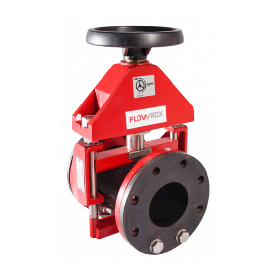
Open Valve (PV)
& Enclosed Valve (PVE)
These instructions must be read carefully and understood
prior to the installation, use, and servicing of this
product.
N O T E
FLOWROX OY
P.O. Box 338
FI-53101 Lappeenranta, Finland
Tel. +358 (0)201 113 311, fax +358 (0)201 113 300
E-mail: sales@flowrox.com
Web: www.flowrox.com
Advertisement
Table of Contents

Related Manuals for FLOWROX PV 80


Summary of Contents for FLOWROX PV 80
- Page 1 PVPVE-190911-EN Installation, operation, and maintenance instructions for Flowrox valves Open Valve (PV) & Enclosed Valve (PVE) These instructions must be read carefully and understood prior to the installation, use, and servicing of this product. N O T E FLOWROX OY P.O.
-
Page 2: Table Of Contents
Model and spare part codes ............... 14 7.1.1 Valve model selection ................14 7.1.2 Sleeve model selection ................15 7.1.3 Sleeve materials for Flowrox valves ............15 APPENDIXES ................18 APPENDIX A: PV- Open Body Assembled ............18 APPENDIX B: PVE-Enclosed Body Assembled ........... 19... -
Page 3: General
1 GENERAL 1.1 General safety instructions for PV & PVE valves In this manual, the following symbols are used to highlight the parts requiring particular attention: SYMBOL DESCRIPTION Risk to personal safety: Neglecting the safety measures can cause serious personal injury or death. DAN GE R Electrical safety: Neglecting the safety measures can cause serious... -
Page 4: Introduction To Device
All valve bodies are flange ended. The standard flange drillings can be made to meet all standards (e.g. DIN, ANSI, BS, AS, JIS). The face to face dimensions of Flowrox valves are according to ANSI/ISA 75.10.02: • 165 mm for valves DN25…DN65 •... -
Page 5: Open Body Valve Pv
2.2.1 Open body valve PV In the open body model the body and the actuator are connected only to one of the end flanges (Fig. 1.). The construction allows a slight deviation in the pipe angle and the valve can act as a vibration absorber. -
Page 6: Valve Function
2.3 Valve function When the valve closes the actuator moves. Do not put tools or parts of your body between the moving valve parts. Note the injury risks (see drawings 3A and 3B). DAN GE R Note the dangerous places (see drawings 3A and 3B)! When the pinch valve closes, two pinch bars, moved by the actuator, squeeze the sleeve,... -
Page 7: Transportation, Storage And Lifting
Normally, a visual inspection of the valve is sufficient. However, if valve has been damaged during transport, contact your nearest Flowrox sales office immediately. 3.2 Storage The sleeves must be stored as follows: •... -
Page 8: Installation
A lengthwise angle deviation of max. 5º in the pipe is allowed (Fig. 5). Fig. 5. Fig. 6. Deviation in the center line of the pipe (C), (Fig. 6): PV 80…100 max. 5 mm PV 125...250 max.10 mm PV 300…500 max. -
Page 9: Enclosed Body Model (Pve)
4.2 Enclosed body model (PVE) Make sure that no inappropriate items get between the valve body and the actuator. 4.3 Both models (PV and PVE) The valve nominal size means the inner diameter of the sleeve. The pipe inner diameter should match this diameter as closely as possible. -
Page 10: Operation
5 OPERATION 5.1 First use Flowrox valves are normally delivered fully assembled and ready to use. Check the condition of the valve visually. After installation to the pipeline, check that all connections are leak-proof. 5.2 During operation During the operation the valve does not normally require any maintenance. The sleeve change is described in 6.2. -
Page 11: Maintenance
6 MAINTENANCE 6.1 Schedule The sleeve is the only part of the valve which is in contact with the medium flowing in the pipeline. With regular sleeve changing, the likelihood of malfunctions in the process decreases. Wear resistance of the sleeve depends on the circumstances of the process and may vary a lot. -
Page 12: Changing Valve Sleeve With Enclosed Model Valve Pve
Put in the new sleeve by pressing the rubber flange on the opposite sides together, pushing its edge as far as possible through the steel flange and wrenching the rest of the sleeve through the flange e.g. with a pry bar / bending iron (see Fig. 9). The rubber flange of the sleeve allows bending. -
Page 13: Adjusting The Valve
6.3 Adjusting the valve After every sleeve change, the closing of the valve has to be checked and adjusted. A wrong adjustment may shorten the lifetime of the sleeve and cause leakage from the valve when the actuator is in the closed position. Control the valve functions (see 2.3). - Page 14 Fig. 10.1. Fig. 10.2. Fig. 10.3. DIMENSION X [mm] PRESSURE CLASS (Bar) VALVE SIZE (mm) 6…10 16…25 25…100 125…250 300…500 Fig. 11. 550…...
-
Page 15: Troubleshooting
In case you cannot find the solution to your problem in the above table, please turn to the nearest Flowrox representative. The serial number and type identification of the valve in question will help getting the prompt answer. -
Page 16: Technical Data
7 TECHNICAL DATA 7.1 Model and spare part codes 7.1.1 Valve model selection PRESSURE FLANGE BODY SHAPE OF OPENING TYPE SIZE (DN) ACTUATOR CLASSES AUXILIARIES DRILLINGS MATERIAL FLANGE TAGS (PN) PV = open 25-1000 M=handwheel 1= 1bar 1 = - 0 = Cast iron / types 1 - 4 L = opening... -
Page 17: Sleeve Model Selection
X = Other, must _/VAC = Vacuum sleeve be specified In spare sleeve orders, please use 4- or 5- figure code marked on the sleeve. 7.1.3 Sleeve materials for Flowrox valves STANDARD SLEEVE MATERIALS FOR FLOWROX VALVES TEMPERATURE RUBBER QUALITY APPLICATION EXAMPLES... - Page 18 • Impermeable to gas Vegetable oils Abrasive media Abrasive materials Polyurethane applications -10°C - +80°C Diluted chemicals • With PU lining Hydrocarbons or solid PU Oils, Lubricants For more information on sleeve materials for Flowrox valves, contact your nearest Flowrox representative.
- Page 19 Opening tags Reinforcing cords Wear-resistant inner lining...
-
Page 20: Appendixes
8 APPENDIXES 8.1 APPENDIX A: PV- Open Body Assembled FLOWROX 1. Valve body 6. Allen screw 2. Flange 7. Valve plate 3. Upper pinch bar 8. Drive screw 4. Lower pinch bar 9. Fix. parts for opening tags 5. Hex. nut... -
Page 21: Appendix B: Pve-Enclosed Body Assembled
8.2 APPENDIX B: PVE-Enclosed Body Assembled FLOWROX 1. Valve body 7. Allen screw 13. Drive screw 2. Upper pinch bar 8. Hex nut 14. Sticker open-closed 3. Lower pinch bar 9. Hex nut 15. Sealing 4. RCH-bushing 10. Washer 16. Fix. parts for opening tags 5.
Need help?
Do you have a question about the PV 80 and is the answer not in the manual?
Questions and answers