
Subscribe to Our Youtube Channel
Related Manuals for Adimec Q-12 CoaXPress Series


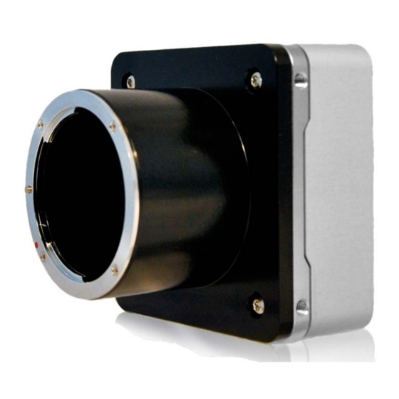
Summary of Contents for Adimec Q-12 CoaXPress Series
- Page 1 OPERATING AND USER MANUAL ________________________________________________________________________________________________________________ Operating and user manual Q-12 CoaXPress series rev2.1...
-
Page 2: Revision History
OPERATING AND USER MANUAL Q-12 CoaXPress series ________________________________________________________________________________________________________________ REVISION HISTORY Revision Page Description of revision Complete revision from the 1.x revision to include the Q-12A180 CXP issue 2.0 camera. Revision history added. Added remark about defect pixels and max frame rate in binned mode. -
Page 3: About Adimec
Our high resolution cameras offer a unique combination of excellence in image quality, speed, and reliability. With optimized functionality for the needs of specific applications, Adimec cameras exceed general purpose. Adimec is a reliable partner with a focus on establishing long term relationships through a worldwide network of highly qualified engineers. -
Page 4: Table Of Contents
OPERATING AND USER MANUAL Q-12 CoaXPress series ________________________________________________________________________________________________________________ TABLE OF CONTENTS REVISION HISTORY .............................. 2 ABOUT ADIMEC ..............................3 TABLE OF CONTENTS ............................4 INTRODUCTION .............................. 5 ........................5 RODUCT HIGHLIGHTS .......................... 5 BOUT THIS MANUAL ..................6 IST OF FREQUENTLY USED ABBREVIATIONS ................ -
Page 5: Introduction
OPERATING AND USER MANUAL Q-12 CoaXPress series ________________________________________________________________________________________________________________ 1 INTRODUCTION The Quartz CMOS camera described in this manual provides 12 Mpx resolution through a CoaXPress interface. The sensor has a global shutter architecture, combined with CCD like image quality and reliability. Unlike competitors who are offering general purpose cameras, our products are developed with the specific needs of OEMs and their applications in mind. -
Page 6: List Of Frequently Used Abbreviations
1.4 Waste Electrical and Electronic Equipment With regard to waste electrical and electronic equipment (WEEE), Adimec wishes to follow the Directive 2002/96/EC of the European Parliament and of the Council. The purpose of this Directive is, as a first priority, the prevention of waste electrical and electronic equipment (WEEE), and in addition, the reuse, recycling and other forms of recovery of such wastes so as to reduce the disposal of waste. -
Page 7: Liability
Adimec Advanced Image Systems B.V. cannot be held responsible for any technical or typographical errors and reserves the right to make changes to the product and manuals without prior notice. Adimec Advanced Image Systems B.V. makes no warranty of any kind with regard to the material contained within this document, including, but not limited to, the implied warranties of merchantability and fitness for a particular purpose. -
Page 8: Safety Precautions
OPERATING AND USER MANUAL Q-12 CoaXPress series ________________________________________________________________________________________________________________ 2 SAFETY PRECAUTIONS NOTE: A CMOS sensor camera is a sensitive device. Please read the following precautions carefully before continuing unpacking or operating the camera. NOTE: It is advised to unpack and handle the camera in a clean ESD protected working area. - Page 9 Adimec. Cameras without RMA number will be rejected. Once the camera is arrived at Adimec the camera will be investigated to proof possible repair or grant your warranty claim. In case of repair the repair costs will be quoted. After your approval of the repair cost camera will be repaired and returned.
-
Page 10: Quick Start Guide
A general quick start guide is therefore difficult to provide. NOTE: The Adimec support department has a couple of frame grabbers available. Inform at support@adimec.com which frame grabber specific quick install guides are available or can be created. -
Page 11: Interfaces
OPERATING AND USER MANUAL Q-12 CoaXPress series ________________________________________________________________________________________________________________ 4 INTERFACES In this chapter the electrical interfaces as well as the optical interface are described. 4.1 Connector overview Figure 4-1: Camera back overview. Table 4-1: Camera connections. Connector Connector type Description... -
Page 12: Electrical Interfaces
OPERATING AND USER MANUAL Q-12 CoaXPress series ________________________________________________________________________________________________________________ 4.2 Electrical interfaces 4.2.1 Power and CoaXPress connectors The CoaXPress interface supports communication in two directions. Power, control data and trigger signals are transferred from the frame grabber to the camera and video data is transferred from the camera to the frame grabber. - Page 13 OPERATING AND USER MANUAL Q-12 CoaXPress series ________________________________________________________________________________________________________________ 4.2.2 CoaXPress status LEDs Next to the CoaXPress connector a multi-color LED status indicator is present. The meaning for each LED indication is shown in Table 4-3, while Table 4-4 lists the frequencies of the fast and slow flashes.
- Page 14 ________________________________________________________________________________________________________________ 4.2.3 Adimec Service Port The Adimec Service Port (ASP) interface is available for firmware uploads to the camera. USB driver XR21x141x is required to support communication via the ASP port. The USB connection will be available as a virtual COM port.
- Page 15 OPERATING AND USER MANUAL Q-12 CoaXPress series ________________________________________________________________________________________________________________ Table 4-6: Recommended resistor values R1E ext [Ω] R2E ext [Ω] Vext [V] 1000 Do not apply 2000 4700 Figure 4-3: Recommended terminations strobe output and trigger input 4.2.5 Lensmount overview The Q-12 camera series can be supplied with various optical interfaces. The available interfaces are listed in Table 4-7.
-
Page 16: Control Of The Camera
OPERATING AND USER MANUAL Q-12 CoaXPress series ________________________________________________________________________________________________________________ 5 CONTROL OF THE CAMERA Access to camera functions and data is provided through the CoaXPress (CXP) protocol. The CoaXPress interface is GenICam compliant. GenICam compliant means that an XML is stored in the camera that is used to translate the camera internal register addresses to the user friendly feature nomenclature as defined by the Standard Features Naming Convention, SFNC. - Page 17 OPERATING AND USER MANUAL Q-12 CoaXPress series ________________________________________________________________________________________________________________ Frame grabber manufacturer Adimec Description XML Application GenAPI CoaXPress Camera Translate SFNC syntax to Transmit register address Change setting: Command syntax camera specific register and value according to Write value to according to SFNC...
-
Page 18: Functional Description
OPERATING AND USER MANUAL Q-12 CoaXPress series ________________________________________________________________________________________________________________ 6 FUNCTIONAL DESCRIPTION This chapter contains a functional description of the Q-12A180 camera. It briefly describes the main functions and features of the camera using a simplified block diagram. More in-depth explanations on these functions as well as descriptions on how to control them can be found in the next chapters of this manual. - Page 19 Both CXP 1.0 and 1.1.1 formats are supported and can be configured. Standard the camera is configured for CXP 1.1.1. Contact Adimec if the camera needs to be configured for CXP 1.0.
-
Page 20: Feature Reference
However Invisible Adimec advises to not use these features. For this reason they are not explained in this manual. The features set to invisible are listed at the end of this Chapter. -
Page 21: Requirements For Changing Settings
OPERATING AND USER MANUAL Q-12 CoaXPress series ________________________________________________________________________________________________________________ In some exceptional cases, to improve the readability of the manual a deviation from this lay-out might be used. For example, multiple read only features are sometimes listed in a single table. -
Page 22: Bootstrap Coaxpress
OPERATING AND USER MANUAL Q-12 CoaXPress series ________________________________________________________________________________________________________________ Section Feature name Description BandClearAll (only when BandEnable = true) Remove all bands from non volatile memory. UserSet Control UserSetLoad Loads the User Set specified by UserSetSelector to the device and makes it active. - Page 23 OPERATING AND USER MANUAL Q-12 CoaXPress series ________________________________________________________________________________________________________________ Name Visibility Description WidthAddress HeightAddress AcquisitionModeAddress AcquisitionStartAddress This feature provides the address in the manufacturer- specific register space of the feature with the corresponding name. AcquisitionStopAddress PixelFormatAddress DeviceTapGeometryAddress Image1StreamIDAddress Indicates the Device support of the optional high speed HsUpconnection upconnection.
-
Page 24: Device Control
OPERATING AND USER MANUAL Q-12 CoaXPress series ________________________________________________________________________________________________________________ 7.3.3 Guru writable Bootstrap features Features with a “Guru” visibility level control advanced camera settings. If these features are used incorrectly the camera might not work properly anymore. Most of the time guru parameters mainly have use in debugging. - Page 25 OPERATING AND USER MANUAL Q-12 CoaXPress series ________________________________________________________________________________________________________________ 7.4.2 BuiltInTest | RO | E | BuiltInTest can give multiple error messages at the same time. The error values are then added together. To decode which error has occurred start with the largest value that fits into the returned BuiltInTest value and then subtract it.
-
Page 26: Image Format Control
OPERATING AND USER MANUAL Q-12 CoaXPress series ________________________________________________________________________________________________________________ 7.4.3 DeviceUserID | RW | B | User-programmable device identifier. The string is directly written to non- String volatile memory. Up to 16 Characters can be used. 7.4.4 DeviceIndicatorMode | RW | E | Inactive Turn off the status indicator LEDs. - Page 27 OPERATING AND USER MANUAL Q-12 CoaXPress series ________________________________________________________________________________________________________________ 7.5.3 Height | RW | B | 32 to 3072 Set the height of the image in pixels. Increment: 4 ISSUE 2 NOTE: When binning is enabled, the maximum range and increment have to be divided by two.
- Page 28 OPERATING AND USER MANUAL Q-12 CoaXPress series ________________________________________________________________________________________________________________ For 2x2 binning, the ProgrammableGainAmplifier and SensorBitDepth features are not available. In binned mode the PGA gain is set to 1 and the sensor bit depth to 10 bit. Separate DF_ and BF_ column calibrations are available for sensor binning for both average and summed binning modes.
- Page 29 OPERATING AND USER MANUAL Q-12 CoaXPress series ________________________________________________________________________________________________________________ 7.5.11 ReverseY | RW | E | The output image is flipped horizontally. For a color camera, the pixel True format is updated automatically to reflect the correct Bayer phase. The Region of interest is applied after the flipping.
- Page 30 Table 7-4: The influence of the ReverseX and ReverseY feature on PixelFormat. 7.5.13 TestImageSelector | RW | B | No test pattern is shown. Specific Adimec test pattern with grey bars, color bars (only active in a AdimecTestPattern color camera) and contour lines, see Figure 7-2.
- Page 31 0 or 1023 Figure 7-2: The Adimec Test Pattern in a 10 bit pixel resolution, black is 0 and white is 1023. The test image is defined in 10 bit. When an 8 bit pixel format is selected the lowest 2 bits are discarded. When the region of interest gets too small parts of the test pattern will disappear.
-
Page 32: Acquisition Control
OPERATING AND USER MANUAL Q-12 CoaXPress series ________________________________________________________________________________________________________________ 7.5.15 CrosshairOverlay | RW | E | Add a crosshair overlay to the image sent by the device. The crosshair is True applied to the center of the image. False No crosshair will be added to the camera image. - Page 33 OPERATING AND USER MANUAL Q-12 CoaXPress series ________________________________________________________________________________________________________________ 7.6.7 AcquisitionMaxFrameRate | WO | B | Set the camera to the maximum frame rate as is possible with the current Command settings. This function could be also used to calculate the maximum achievable frame rate in case the camera is set in a slave exposure mode.
- Page 34 OPERATING AND USER MANUAL Q-12 CoaXPress series ________________________________________________________________________________________________________________ 7.6.10 ExposureMode | RW | B | The camera can be operated in 5 exposure modes. Refer to Figure 7-4 for a description of these modes. Free run mode. The camera is master: frame period and integration time...
- Page 35 OPERATING AND USER MANUAL Q-12 CoaXPress series ________________________________________________________________________________________________________________ Table 7-5: Minimum exposure time. Please note that the minimum value in the ExposureTime feature is 1 µs. Therefore the minimum exposure time equals the FOT + 1 µs. SensorBitDepth t_sens (µs) Min.
- Page 36 OPERATING AND USER MANUAL Q-12 CoaXPress series ________________________________________________________________________________________________________________ TriggerWidth Trigger Configured exposure time Actual exposure time Frame output Configured exposure time Co gu ed Actual e posu e t e exposure time ctua e posu e t e Frame output...
- Page 37 OPERATING AND USER MANUAL Q-12 CoaXPress series ________________________________________________________________________________________________________________ 7.6.11 ExposureTime | RW | B | Set the exposure time (in 1µs steps). The exposure time is not corrected for the light sensitive FOT of the sensor. To obtain the actual Min: 1µs...
-
Page 38: Counter And Timer Control
OPERATING AND USER MANUAL Q-12 CoaXPress series ________________________________________________________________________________________________________________ 7.7 Counter and timer control This group contains the features related with externally providing the camera with a trigger signal. 7.7.1 FlashStrobeMode | RW | B | Disabled Flash strobe inactive. The flash strobe output will become active during the integration time of the Automatic sensor (regardless of the exposure mode). -
Page 39: High Dynamic Range Mode
OPERATING AND USER MANUAL Q-12 CoaXPress series ________________________________________________________________________________________________________________ 7.8 High Dynamic Range Mode In the camera, a high optical dynamic range can be realized by setting the camera to a piece-wise linear response with up to 3 slopes. This section describes briefly the HDR features. An application note is available for a more detailed explanation. - Page 40 OPERATING AND USER MANUAL Q-12 CoaXPress series ________________________________________________________________________________________________________________ PIXEL SATURATION LEVEL Q12 Kneepoint 1 Q12 Node 1 Kneepoint 2 Q12 Node 2 MultiSlopeTime Node 1 (%) 100% (total integrationtime) Figure 7-9: The graph above illustrates how the nodes are defined with the HDR features. It also shows how the nodes define the kneepoints as shown in Figure 7-10.
-
Page 41: Analog Control
OPERATING AND USER MANUAL Q-12 CoaXPress series ________________________________________________________________________________________________________________ 7.9 Analog control Analog control functions like gain and white balance can be found in this group. 7.9.1 GainSelector | RW | B | Gain features will influence all pixels. Red (Color Only) Gain features will only influence the red pixels. - Page 42 OPERATING AND USER MANUAL Q-12 CoaXPress series ________________________________________________________________________________________________________________ 7.9.4 BlackLevel | RW | B | 0 to 511 Control the analog black level as an absolute physical value. Increment: 1 This feature is automatically updated if any of the following features is changed: BlackLevelRaw For the 8-bit pixel formats, the configured value is presented at the video output as BlackLevel/4.
-
Page 43: Sensor
OPERATING AND USER MANUAL Q-12 CoaXPress series ________________________________________________________________________________________________________________ 7.9.10 WhiteBalanceOffsetY | RW | E | Color Only 0 to SensorHeight-2 Vertical offset, relative to OffsetY, for the “white balance region of interest”, Increment: 1 the region that is used for white balance calibration. (in pixels). -
Page 44: Factory
OPERATING AND USER MANUAL Q-12 CoaXPress series ________________________________________________________________________________________________________________ ISSUE 2 NOTE: This feature is automatically updated if any of the following features is changed: BinningHorizontal, BinningVertical 7.10.2 ProgrammableGainAmplifier | RW | G | The programmable gain amplifier controls the analog gain in the sensor. Changing the sensors analog gain amplifier will affect the maximum full well capacity and read noise of the image sensor. - Page 45 OPERATING AND USER MANUAL Q-12 CoaXPress series ________________________________________________________________________________________________________________ 7.12.2 LUTSelection | RW | E | ISSUE 2 ONLY ProgrammableLUT In this mode the LUT can be fully programmed. In this mode a gamma curve will be used as the LUT. The gamma will be applied by filling the LUT according to following formula: ����������...
-
Page 46: Transport Layer Control
OPERATING AND USER MANUAL Q-12 CoaXPress series ________________________________________________________________________________________________________________ This feature is automatically updated if any of the following features is changed: LUTStart, LUTEnd 7.12.8 GammaFactor | RW | E | ISSUE 2 ONLY 0.01 to 10 Set the Gamma factor. - Page 47 OPERATING AND USER MANUAL Q-12 CoaXPress series ________________________________________________________________________________________________________________ 7.14.1 How to use the defect pixel correction This section describes some frequently occurring tasks with respect to the defect pixel correction functionality. Task Description Add defect The following steps are required to add a defect pixel to the defect pixel list: Write the defect pixel location (origin of the most left top pixel has coordinate 0;0): DefectPixelWriteX and DefectPixelWriteY.
- Page 48 OPERATING AND USER MANUAL Q-12 CoaXPress series ________________________________________________________________________________________________________________ 7.14.3 DefectPixelTestMode | RW | E | Turn off the defect pixel test mode. Mark defects white on video, for use in a dark MarkDefectsWhiteOnVideo environment. Mark defects black on video, for use in a light MarkDefectsBlackOnVideo environment.
- Page 49 OPERATING AND USER MANUAL Q-12 CoaXPress series ________________________________________________________________________________________________________________ 7.14.9 DefectPixelWriteY | RW | E | Select the vertical coordinate of a defect pixel that needs to be corrected. 0 to 3072 Defect pixel coordinates x, y are referenced to the full sensor image of Increment: 1 4096 x 3072 pixels, where (0, 0) is the top-left most image pixel.
-
Page 50: Dark Field
OPERATING AND USER MANUAL Q-12 CoaXPress series ________________________________________________________________________________________________________________ 7.15 Dark field Two independent dark field correction mechanisms are present in the camera, i.e. DF_BlackClamp and DF_ColumnOffsetCorrection. 7.15.1 DF_BlackClamp | RW | E | Enable the dark field black clamp. There will be 8 pixels on each side of the image over the full sensor height that will appear dark. -
Page 51: Bright Field
OPERATING AND USER MANUAL Q-12 CoaXPress series ________________________________________________________________________________________________________________ 7.15.5 DF_RestoreFactory | WO | E | Restore the correction to the factory calibration status. Only the factory set in the selected operating condition will be loaded (SensorBitDepth in Command combination with the selected ProgrammableGainAmplifier). - Page 52 OPERATING AND USER MANUAL Q-12 CoaXPress series ________________________________________________________________________________________________________________ 7.16.2 BF_AutoLevelAdjust | RW | E | Before performing the calibration the camera will adjust the integration time True such that the video level will equal the level that is set in the BF_calibrationVideoLevel feature.
-
Page 53: Lf Ff Calibration
OPERATING AND USER MANUAL Q-12 CoaXPress series ________________________________________________________________________________________________________________ 7.16.6 BF_Status | RO | E | The calibration is successfully finished and stored in non volatile BF_CalibrateOK memory. Calibration failed, configured video level cannot be reached with BF_UnderExposed adjusted integration time. Increase exposure level and recalibrate. - Page 54 OPERATING AND USER MANUAL Q-12 CoaXPress series ________________________________________________________________________________________________________________ 7.17.1 LF_FF_Correction | RW | B | True Enables the spatially low frequency flat field correction. False Disables the spatially low frequency flat field correction. This feature is automatically updated if any of the following features is changed: BandEnable 7.17.2 LF_FF_ReferencePoint | RW | B |...
- Page 55 OPERATING AND USER MANUAL Q-12 CoaXPress series ________________________________________________________________________________________________________________ Trigger N+1 Trigger Trigger N+2 CXP Uplink Set B Set C FFC Select Window 200 us 10 us 200 us 10 us Frame Frame N Frame N+1 FFC Set Set A Set B...
- Page 56 OPERATING AND USER MANUAL Q-12 CoaXPress series ________________________________________________________________________________________________________________ LF_FF_ImageTooDark The average video level is below 12.5% of the full scale. LF_FF_ImageTooBright The average video level is above 90% of the full scale. LF_FF_ImagePeakTooLow The peak video level is below 12.5% of the full scale.
- Page 57 OPERATING AND USER MANUAL Q-12 CoaXPress series ________________________________________________________________________________________________________________ LF_FF_SequenceProgrammingNotStarted The sequence programming has not yet started. The maximum sequence length of 2000 entries has LF_FF_SequenceProgramLimitReached been reached. The current sequence has been saved to non-volatile LF_FF_SequenceSaved memory. The sequence that was stored in the non-volatile LF_FF_SequenceLoaded memory has been loaded as the active sequence.
- Page 58 NOTE: This functionality is not suitable to write a custom correction set to the camera. NOTE: The set that is written to the camera has to originate from another Adimec camera with the same sensor type.
- Page 59 OPERATING AND USER MANUAL Q-12 CoaXPress series ________________________________________________________________________________________________________________ 5. Read the raw set data from the camera by requesting 887x LF_FF_RawSetData for data. The data format is 64 bit. NOTE: Sending too many or too few data requests to LF_FF_RawSetData will cause an error.
-
Page 60: User Set Control
OPERATING AND USER MANUAL Q-12 CoaXPress series ________________________________________________________________________________________________________________ LF_FF_RawSetDataSizeNotCorrect The size of the written set data is not correct. LF_FF_RawSetDataCRCerror A CRC error occurred while transferring the raw set data. This feature is automatically updated if any of the following features is changed: LF_FF_RawSetDataEnd, LF_FF_RawSetDataReadStart, LF_FF_RawSetDataWriteStart 7.18 User set control... - Page 61 OPERATING AND USER MANUAL Q-12 CoaXPress series ________________________________________________________________________________________________________________ Table 7-7: User savable features and default values Group Feature Default Remark DeviceControl DeviceUserID <empty> DeviceIndicatorMode Active ImageFormatControl Width 4096 Height 3072 OffsetX OffsetY ReverseX ReverseY PixelFormat Mono10/ BayerGB10 TestImageSelector TestImageVideoLevel CrossHairOverlay...
- Page 62 OPERATING AND USER MANUAL Q-12 CoaXPress series ________________________________________________________________________________________________________________ BlackLevelRaw WhiteBalanceWidth 4096 WhiteBalanceHeight 3072 WhiteBalanceOffsetX WhiteBalanceOffsetY Sensor SensorBitDepth Resolution_10_Bit ProgrammableGainAmplifier LUTControl LUTEnable LUTSelection ProgrammableLUT GammaFactorRaw DefectPixel DefectPixelCorrectionEnable DefectPixelTestMode DarkField DF_BlackClamp DF_ColumnOffsetCorrection BrightField BF_ColumnGainCorrection BF_AutoLevelAdjust BF_CalibrationVideoLevel BF_OutputImagesDuring Calibration LF_FF_Calibration LF_FF_ReferencePoint Peak LF_FF_SetSelectionMode...
-
Page 63: Band
OPERATING AND USER MANUAL Q-12 CoaXPress series ________________________________________________________________________________________________________________ 7.19 Band With the band function rectangular areas for sensor read out can be selected. By using the band function not every sensor line has to be read out which might increase the frame rate. All created bands will be combined into a single image at the interface output. - Page 64 OPERATING AND USER MANUAL Q-12 CoaXPress series ________________________________________________________________________________________________________________ 7.19.5 BandReadOffsetY | RO | E | Integer Returns the y offset of the band selected by BandSelector. This feature is automatically updated if any of the following features is changed: BandAdd, BandClearAll, BandRemove, BandLoad, BandSelector 7.19.6 BandReadHeight | RO | B |...
- Page 65 OPERATING AND USER MANUAL Q-12 CoaXPress series ________________________________________________________________________________________________________________ 7.19.15 BandStatus | RO | B | BandStatusNoError No error occurred in programming the bands. BandStatusOutsideAvailableHeight The band cannot be created as it is outside the available height. BandStatusOverlap The band overlaps with an already existing band.
-
Page 66: Appendix A: Cmos Sensor Cleaning Instructions
OPERATING AND USER MANUAL Q-12 CoaXPress series ________________________________________________________________________________________________________________ APPENDIX A: CMOS SENSOR CLEANING INSTRUCTIONS When you would like to clean the CMOS sensor because the sensor got contaminated with dust particles that influence your image quality, this appendix describes the right procedure with the lowest chance on damage. - Page 67 OPERATING AND USER MANUAL Q-12 CoaXPress series ________________________________________________________________________________________________________________ Figure A-0-1: Front view of the camera. The lens mount fixation points are indicated with the black arrows. 5. Install a lens, power up the camera, set the lens at a small aperture (F16) and point the lens at a bright source.
-
Page 68: Appendix B: C++ Example, Transfer An Lf Ff Calibration Set
OPERATING AND USER MANUAL Q-12 CoaXPress series ________________________________________________________________________________________________________________ APPENDIX B: C++ EXAMPLE, TRANSFER AN LF FF CALIBRATION SET This appendix shows an example script that moves a low frequency flat field calibration set to a set with a different index in the same camera. With small adjustments it can be used to transfer a calibration set between different Adimec cameras with the same sensor. - Page 69 OPERATING AND USER MANUAL Q-12 CoaXPress series ________________________________________________________________________________________________________________ /********************************************************************************/ * File name: moveLFFFSet.cpp * Synopsis: This program demonstrates how to move one LF FF set to another one. #include <mil.h> #include <stdint.h> /* Required for uint64_t support */ /* Determine the number of required transfers for the LF FFC set,...
- Page 70 OPERATING AND USER MANUAL Q-12 CoaXPress series ________________________________________________________________________________________________________________ sprintf_s(Cmd, "LF_FF_RawSetData"); (i = 0; i < TRANSFERS; i++) { MdigInquireFeature(MilDigitizer, M_FEATURE_VALUE, Cmd, M_TYPE_INT64, &lf_ff_data[i]); printf("Record: %i - %lli\n", i, lf_ff_data[i]); /* End the reading process */ sprintf_s(Cmd, "LF_FF_RawSetDataEnd"); sprintf_s(CmdParam, "1"); MdigControlFeature(MilDigitizer, M_FEATURE_VALUE_AS_STRING, Cmd, M_TYPE_STRING, CmdParam);...
Need help?
Do you have a question about the Q-12 CoaXPress Series and is the answer not in the manual?
Questions and answers