Table of Contents
Advertisement
Quick Links
Advertisement
Table of Contents

Subscribe to Our Youtube Channel
Related Manuals for Adimec Camera Link OPAL Series


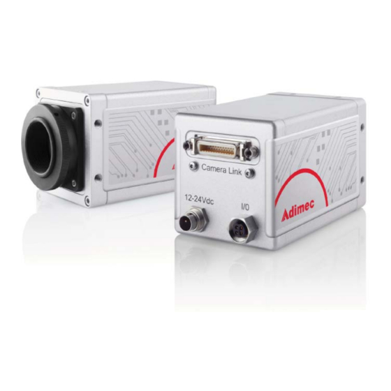
Summary of Contents for Adimec Camera Link OPAL Series
- Page 1 Operating and user manual OPAL FAMILY CAMERA LINK MODELS...
- Page 2 OPERATING AND USER MANUAL OPAL FAMILY...
- Page 3 OEMs around the world, we utilize the synergy between these segments to shine in terms of image quality, speed, dynamic range and reliability. Adimec is the only company in the market that merges the specific needs of its highly demanding customers to its technological inventiveness, generating vision solutions of outstanding quality.
-
Page 4: Table Of Contents
OPERATING AND USER MANUAL OPAL-CL Contents ABOUT THIS MANUAL Document applicability How this guide is organized Liability GENERAL INTRODUCTION Product highlights Applications Camera models RoHS Electromagnetic Compatibility (EMC) SAFETY INFORMATION General Precautions Safety symbols Handling INSTALLATION OPAL interface connections Mechanical Environmental Thermal management CONTROL OF THE CAMERA... - Page 5 OPERATING AND USER MANUAL OPAL-CL Obtaining the camera build state User storage IMAGE CAPTURING AND VIDEO OUTPUT Introduction Selecting Image Acquisition Mode Used parameters and timing table Exposure and image output overlap Image Aquisition in continuous mode Image Aquisition in normal control mode Image Acquisition in delayed transfer mode (optional) Image Acquisition in double transfer mode (optional) Image Acquisition in double delayed transfer mode (optional)
- Page 6 OPERATING AND USER MANUAL OPAL-CL Maintenance Repair and modification OPTION: AEC/VEM 10.1 Introduction 10.2 Performance 10.3 AEC commands 10.4 VEM commands (Monochrome only) 10.5 Controlling the AEC setpoint and VEM measurement window REFERENCE 11.1 Camera Link port configuration 11.2 Camera Link video output 11.3 Basic serial communication parameters of the camera 11.4...
-
Page 7: About This Manual
OPERATING AND USER MANUAL OPAL FAMILY About this manual This manual is intended for systems designers and engineers using the Adimec Machine Vision camera series. This manual provides the necessary information for setting-up, configure and maintaining the camera. We strongly recommend reading this manual, at least chapters three and four before you unpack or operate the camera. -
Page 8: Liability
Liability Every care has been taken in the preparation of this manual. Please inform your Adimec Business Office of any inaccuracies or omissions. Adimec Advanced Image Systems B.V. cannot be held responsible for any technical or typographical errors and reserves the right to make changes to the product and manuals without prior notice. - Page 9 OPERATING AND USER MANUAL OPAL FAMILY...
- Page 10 OPERATING AND USER MANUAL OPAL FAMILY...
-
Page 11: General Introduction
OPERATING AND USER MANUAL OPAL FAMILY General introduction Congratulations on the purchase of your OPAL camera. Your Adimec camera has been extensively tested in order to be sure that we delivered a high quality product. The OPAL camera is designed for Industrial Machine Vision and measurement systems. -
Page 12: Camera Models
OPERATING AND USER MANUAL OPAL FAMILY GENERAL INTRODUCTION Camera models The Adimec Machine Vision camera series are available in several models. Primary differences are the resolutions and frame speeds. MODEL RESOLUTION FRAME RATE MONO./COLOR INTERFACE OPAL-1000m 1024 x 1024 123,1 fps... -
Page 13: Safety Information
SAFETY INFORMATION OPERATING AND USER MANUAL OPAL FAMILY Safety information General A CCD camera is a sensitive device. In order to ensure your warranty on this product, please read the following paragraphs scarefully before you continue to unpack and operate the camera. •... - Page 14 OPERATING AND USER MANUAL OPAL FAMILY SAFETY INFORMATION...
-
Page 15: Installation
INSTALLATION OPERATING AND USER MANUAL OPAL FAMILY Installation Camera Link at Base configuration is a universal way of connecting the CL series camera to a framegrabber and suitable for high speed applications. The OPAL camera is also available with Coaxpress or GigE Vision interface. It goes beyond the scope of this manual to elaborate on this. - Page 16 Binder series 712 type 99-0402-00-02 (straight) Binder series 712 type 99-0402-70-02 (90 degrees angle) Power cable All OPAL cameras can be delivered with a power cable (2 meter) as accessory. It is available as Adimec part no. 102830 WIRE FUNCTION White...
- Page 17 INSTALLATION OPERATING AND USER MANUAL OPAL FAMILY 4.1.2. I/O Interface I/O connection An input for external triggering of the camera is available at the I/O connector. Also a trigger output signal from the camera to control an external flash light is available at this connector.
- Page 18 Figure 4.5: Female Camera Link connector at the camera. Standard Camera Link cables can be ordered at Adimec. WARNING: Avoid damage by preventing the entry of foreign objects or dirt to the connectors. The tightening torque for the retention screws may not exceed 0.29 Nm.
-
Page 19: Mechanical
INSTALLATION OPERATING AND USER MANUAL OPAL FAMILY Mechanical 4.2.1. Outline dimensions Camera Link series camera Camera Link 12 - 24 Vdc Figure 4.6: Camera outline drawing Camera Link camera. 4.2.2. Lensmount Figure 4.7: 4 Torx screws that hold the C-format lensmount (front view of the camera) Upon delivery, the OPAL1000, 1600, 2000 and 4000 cameras are fitted with a C-format lensmount by means of four screws as indicated in figure 4.7. -
Page 20: Environmental
OPERATING AND USER MANUAL OPAL FAMILY INSTALLATION Vignetting can be expected with F# values smaller than F4 when using a C-format lensmount. NOTE: The protective cap may only be removed by pulling it off. Never try to unscrew the protective cap as this will dissasemble the C-format lensmount. -
Page 21: Thermal Management
INSTALLATION OPERATING AND USER MANUAL OPAL FAMILY Take appropriate precautions to prevent ESD: The camera is shipped in a special bag designed to prevent ESD. For storage, keep the device in the bag. • Never insert a metal tool or knife into the bag and rip it open, but open it by hand. It is advised to keep this bag;... - Page 22 OPERATING AND USER MANUAL OPAL FAMILY...
-
Page 23: Control Of The Camera
• By means of your own dedicated software In addition to an explanation on how to use the Adimec communication applications, you will also find a description of the command structure. This description should be read and understood when controlling the camera either with the Adimec Command Console application or with your own dedicated software. - Page 24 OPERATING AND USER MANUAL OPAL FAMILY CONTROL OF THE CAMERA - Video application - Ext. control - Serial com Camera image data framegrabber Dashed = software Comm. channel camera control Solid = hardware Figure 5.2: Camera Link mapped by means a virtual COM-port supported by the Frame Grabber After launching the application it will autodetect the COM-port number or other communication channel.
- Page 25 CONTROL OF THE CAMERA OPERATING AND USER MANUAL OPAL FAMILY 5.2.1. User settings tab FUNCTION CONTROL Acquisition mode In the frame Mode, one of the different Image acquisition modes can be set. The Continuous and Control modes are standard. Delayed control, Double transfer, Delayed transfer are optional.
- Page 26 OPERATING AND USER MANUAL OPAL FAMILY CONTROL OF THE CAMERA FUNCTION CONTROL Store camera settings The actual settings of every tab, except the settings of tab User storage, will be stored simultaneously. To store the current settings select the desired settings from 1 to 9 in the drop down box and press SAVE.
- Page 27 CONTROL OF THE CAMERA OPERATING AND USER MANUAL OPAL FAMILY 5.2.4. Camera control tab Function CONTROL Exposure select In the frame Exposure select, the method of controlling the exposure start trigger can be selected. This can be done by each and every one of the CC1..CC4 of the Camera Link connector or the external trigger input on the I/O-connector.
-
Page 28: Controlling The Camera With The Command Console Application
OPERATING AND USER MANUAL OPAL FAMILY CONTROL OF THE CAMERA Controlling the camera with the Command Console application The Command Console application is a basic communication console. Commands entered at the prompt line are directly sent to the camera. The program will run on W9x, NT, 2000 and XP (32 bit) operating systems and in 32 bit mode on Vista (64 bit) systems.. - Page 29 CONTROL OF THE CAMERA OPERATING AND USER MANUAL OPAL FAMILY 5.5.3. Request commands Actual camera settings can be obtained via a request command. Commands with a question mark after the keyword are recognized as request commands. Request command example: Command syntax: BS? The camera will reply with one or more parameters, separated by a semicolon (;) if necessary.
- Page 30 OPERATING AND USER MANUAL OPAL FAMILY...
-
Page 31: Managing Camera Settings
‘power-up default’ setting. This is called power-up set 0. This default power-up set 0 is determined by Adimec can not be altered. Instead, up to nine additional user defined sets of power-up settings can be stored. This way, user defined settings can be applied at powering up. -
Page 32: Obtaining The Camera Identification String
Table 6.2: Example of the replied ID messages for monochrome and color cameras Obtaining the camera model identification The model identification (Adimec Part ID) can be obtained from the camera by means of the Model Identification command. Command syntax: MID? Reply message: “xxxxxx... -
Page 33: Obtaining The Camera Build State
Where x.xx stands for camera issue, y.yy indicates the microcontroller fimware version and z.zz indicates the FPGA firmware version. NOTE: When requesting support on some features of the camera, Adimec may request the build state information, including firmware versions, in order to optimize support. - Page 34 OPERATING AND USER MANUAL OPAL FAMILY...
-
Page 35: Image Capturing And Video Output
IMAGE CAPTURING AND VIDEO OUTPUT OPERATING AND USER MANUAL OPAL-FAMILY Image capturing and video output Introduction Image acquisition is possible in several modes. In this chapter each mode is described in a separate paragraph. Some general remarks: • Image Acquisition takes some time, depending on camera settings. In either mode, if the user tries to capture frames at a higher frame rate than the acquisition time allows, the camera will not behave as expected. -
Page 36: Used Parameters And Timing Table
OPERATING AND USER MANUAL OPAL-FAMILY IMAGE CAPTURING AND VIDEO OUTPUT Used parameters and timing table The next paragraphs about the acquisition modes make use of timing diagrams. These diagrams list parameters that are gathered in table 7.2 below. CAMERA MODEL TD_IT_BGN TD_IT_END T_DTM_... -
Page 37: Image Aquisition In Continuous Mode
IMAGE CAPTURING AND VIDEO OUTPUT OPERATING AND USER MANUAL OPAL-FAMILY Minimal: Minimal: Minimal: t_frame_min t_frame_min t_frame_min Exposure control Sensor Int. im 1 Int. im 2 Int. im 3 Int. im 4 integration Image Output im 2 Output im 3 Output im 1 output Figure 7.1: Timing details normal control mode showing integration and image output overlap. - Page 38 OPERATING AND USER MANUAL OPAL-FAMILY IMAGE CAPTURING AND VIDEO OUTPUT Both parameters can be read back from the camera Command syntax: IT? Reply message: x Where x = integration time or exposure time in units of 10 μs. Command syntax: FP? Reply message: x Where x = frame period in units of 10 μs.
-
Page 39: Image Aquisition In Normal Control Mode
IMAGE CAPTURING AND VIDEO OUTPUT OPERATING AND USER MANUAL OPAL-FAMILY Image Aquisition in normal control mode In normal control mode camera timing is controlled by means of an external signal. The parameters for integration time and frame period can still be set and read-out but have no meaning. Refer to figure 7.4 for a simplified basic timing diagram. -
Page 40: Image Acquisition In Delayed Transfer Mode (Optional)
OPERATING AND USER MANUAL OPAL-FAMILY IMAGE CAPTURING AND VIDEO OUTPUT NOTE: The selection and behavior of the control signals are explained in detail in par. 7.11 and 7.12. Image Acquisition in delayed transfer mode (optional) In delayed transfer mode camera timing is controlled by means of two external signals. The parameters for integration time and frame period can still be set and read-out but have no meaning. -
Page 41: Image Acquisition In Double Transfer Mode (Optional)
IMAGE CAPTURING AND VIDEO OUTPUT OPERATING AND USER MANUAL OPAL-FAMILY NOTE: The selection and behavior of the control signals are explained in detail in par. 7.11 and 7.12. Image Acquisition in double transfer mode (optional) Double transfer mode allows for the capture of two images shortly after each other. Image readout of both images is postponed until integration of the second image is completed. -
Page 42: Image Acquisition In Double Delayed Transfer Mode (Optional)
OPERATING AND USER MANUAL OPAL-FAMILY IMAGE CAPTURING AND VIDEO OUTPUT Image Acquisition in double delayed transfer mode (optional) Double delayed transfer mode also allows for the capture of two images shortly after each other. Image readout of both images is postponed until integration of the second image is completed. Image readout of the second frame is controlled by a separate control signal. -
Page 43: Image Aquisition In It Defined Integration Control Mode (Optional)
IMAGE CAPTURING AND VIDEO OUTPUT OPERATING AND USER MANUAL OPAL-FAMILY 7.10 Image Aquisition in IT defined integration control mode (optional) In IT defined integration control mode the start of integration is controlled by means of an external signal. The parameters for integration time IT can be set to determine the integration time. Refer to figure 7.11 for a simplified basic timing diagram. -
Page 44: Polarity And Choice Of External Triggers
OPERATING AND USER MANUAL OPAL-FAMILY IMAGE CAPTURING AND VIDEO OUTPUT 7.11 Polarity and choice of external triggers 7.11.1. Introduction Controlling integration and read-out in each one of the control inputs can be done by every one of the CC1..CC4 and/or the external trigger input on the I/O-connector. Which control signals control which event is fully programmable. -
Page 45: Read-Out Control
IMAGE CAPTURING AND VIDEO OUTPUT OPERATING AND USER MANUAL OPAL-FAMILY 7.12 Read-out control Exposure control is done by means of the Camera Control Exposure and Camera Control Frame read-out. Read-out control is done by means of the Camera Control Frame readout command. This is applicable in the following modes: •... -
Page 46: Flash Strobe
OPERATING AND USER MANUAL OPAL-FAMILY IMAGE CAPTURING AND VIDEO OUTPUT 7.13 Flash strobe 7.13.1. Flash strobe enable The camera is equipped with strobe output signal on the I/O connector. The strobe can be switched on off by means of the FSE command. Command syntax: FSEx Where x is set to 0 to disable the strobe output and x is set to 1 to enable the strobe output. -
Page 47: Image And Data Formatting
IMAGE AND DATA FORMATTING OPERATING AND USER MANUAL OPAL FAMILY Image and Data Formatting Introduction Although the CCD in the camera has a fixed format there are several possibilities to change the way the CCD is read-out. It is possible to limit the amount of lines read from the CCD (discussed in par 8.2);... - Page 48 OPERATING AND USER MANUAL OPAL FAMILY IMAGE AND DATA FORMATTING For a thorough understanding of the concept please find some properties of the possibilities (including optional binning modes) in the diagram below. The standard OPAL camera only offers two binning modes: no binning (1x) and 2x vertical binning. HBIN VBIN “BIN...
- Page 49 IMAGE AND DATA FORMATTING OPERATING AND USER MANUAL OPAL FAMILY 8.2.2. Frame rate consequences when vertical binning is used If the vertical binning is used, the maximum possible frame rate will be higher than the standard frame rate. The camera will however not automatically increase frame rate when binning is enabled. If the vertical binning is disabled or is switched to a lower binning factor, then the maximum possible frame rate decreases.
-
Page 50: Region Of Interest (Optional)
OPERATING AND USER MANUAL OPAL FAMILY IMAGE AND DATA FORMATTING 8.2.4. Binning without sensitivity consequences OPTIONAL: A special non-standard feature is the Hi-Qmax option. If this option is ordered the electronic gain in the camera will be halved when two (or more when possible) lines are vertically binned. -
Page 51: Burst Mode (Optional)
IMAGE AND DATA FORMATTING OPERATING AND USER MANUAL OPAL FAMILY NOTE: Only even values are expected to be entered at the ROI command. The actual Region of Interest can be read back from the camera. Command syntax: ROI? Reply message: x;y;w;h Where x, y, w and h are representing the values as described above NOTE: Selecting a Region of Interest can be performed together with Burst Mode. - Page 52 OPERATING AND USER MANUAL OPAL FAMILY IMAGE AND DATA FORMATTING To enable the Burst Mode the BMO command is available Command syntax: BMOx Where: x = 0 for normal operation, disabling Burst Mode x = 1 for Burst Mode with automatic image release. An image is output as soon as one complete image is in the buffer memory.
-
Page 53: Vertical Remap
IMAGE AND DATA FORMATTING OPERATING AND USER MANUAL OPAL FAMILY NOTE: In practice, the memory locations that already have been read out during acquisition are available as free memory. As an example; the OPAL-1000 has a memory capacity of 64 images of 12 bit resolution. Maximum acuisition speed is 120 frames per second. -
Page 54: Output Resolution
OPERATING AND USER MANUAL OPAL FAMILY IMAGE AND DATA FORMATTING Enabling and disabling the vertical remap is done by means of the vertical remap command. Command syntax: VRx Where: x=0 denotes no vertical remapping; simultaneous output of top and bottom pixel, no delay. x=1 denotes vertical remapping active;... -
Page 55: Digital Gain
IMAGE AND DATA FORMATTING OPERATING AND USER MANUAL OPAL FAMILY NOTE: When changing the vertical mirror setting, the camera needs initializing of the hardware and therefore will perform a soft-reboot. The camera will need up to 1 second to apply the new settings. A short interruption of camera operation takes place when switching the ReverseY parameter. -
Page 56: Offset (Only For Color)
OPERATING AND USER MANUAL OPAL FAMILY IMAGE AND DATA FORMATTING 8.10 Offset (only for color) In order to enable all captured information to be displayed within the digital domain an offset is applied on the camera output data. Black is not represented by 0, but by the value programmed with the offset command. -
Page 57: Defect Pixels
Up to 3 adjacent pixels can be corrected by the above method. More than 3 adjacent defect pixels can be user programmed, but may not result in a reliable correction. Adimec does not release cameras with more than 3 adjacent defect pixels upon delivery. 8.12.2. - Page 58 OPERATING AND USER MANUAL OPAL FAMILY IMAGE AND DATA FORMATTING where x = number of defect pixels. If n> 0 Reply message: x;y Where x, y are the coordinates of defect pixel number n. Adding a Defect Pixel to the table NOTE: The left top pixel is referred to as 1;1 To add a defect pixel to the table, the DP command can be used Command syntax: DPx;y...
-
Page 59: Output Lookup Table
IMAGE AND DATA FORMATTING OPERATING AND USER MANUAL OPAL FAMILY TEST MODE disabled, normal image. marks defect pixels white on video marks defect pixels black on video shows defect pixels as white on a black background Table 8.6: Defect pixel test mode. The actual setting can be read back from the camera. - Page 60 OPERATING AND USER MANUAL OPAL FAMILY IMAGE AND DATA FORMATTING 8.13.3. Output LookUp Table end. After filling the output look-up table with 4096 vales, the table should be closed. This is done through the OLUTEND command. Command syntax: OLUTEND NOTE: If the camera did not receive exactly 4096 entries, the LUT definition is ended, but LUT data is not saved to non-volatile memory.
-
Page 61: Service & Maintenance
Last received command: too many parameters Last received command: missing parameter(s) Last received command: parameter(s) out of range Last received command: internal Adimec error Loading of settings configuration from non-volatile memory failed (CRC invalid) Writing of settings configuration to non-volatile memory failed (CRC verify failed) - Page 62 Where x;y = 0;0 indicates all tests passed. NOTE: All other codes are of no meaning to the user. When requesting support on some features of the camera, Adimec may request the result of the BIT command, in order to optimize support. 9.1.3.
-
Page 63: Internal Test Pattern Generator
SERVICE & MAINTENANCE OPERATING AND USER MANUAL OPAL FAMILY Internal test pattern generator In order to check the camera and datapath in the system, a test pattern is available. This test pattern generator produces a static, defined picture according to the settings for output resolution, gain and the mode the camera is currently working in. - Page 64 OPERATING AND USER MANUAL OPAL FAMILY SERVICE & MAINTENANCE The test pattern is composed of a black (digital 0) background with superimposed sub-patterns according to the layout shown below: Border Pattern Top gray bars Color Color Gray patches Bottom gray bars Figure 9.1: Test pattern layout.
- Page 65 SERVICE & MAINTENANCE OPERATING AND USER MANUAL OPAL FAMILY 9.2.5. Gray patches x = W/2 - 255 y = H/2 - 127 1920 1921 1922 1983 1984 2045 2046 2047 2048 2049 2050 2111 2112 2173 2174 2175 3840 3841 3842 3903 3904...
-
Page 66: Information Overlay Data Format
OPERATING AND USER MANUAL OPAL FAMILY SERVICE & MAINTENANCE 9.2.7. Color bar Left: x = w/2 - 319 Right: x = w/2 + 289 Y - pos: y = h/2 - 437 NOTE: The colored pixels indicated “On” have a value of 4095. Pixels indicated “X” have a value of 0. Information Overlay data format When enabled, the top left most active video pixels in the output image are replaced by 8 data pixels. -
Page 67: Cleaning
Cleaning of a CCD sensor is a rather difficult task. Due to the possibility of creating scratches on the cover glass or damaging the CCD by ESD, Adimec does not recommend cleaning the optical surface of the sensor, unless by necessity. -
Page 68: Maintenance
Maintenance No specific maintenance other than cleaning is applicable. Repair and modification Repair, modification and replacement of parts shall be done only by Adimec to maintain compliance with the directive 89/336/EEC electromagnetic compatibility... -
Page 69: Option: Aec/Vem
OPTION: AEC/VEM OPERATING AND USER MANUAL OPAL FAMILY Option: AEC/VEM 10.1 Introduction The AEC option is available on all OPAL family members. This application note describes the functionality of the option. AEC stands for Automatic Exposure Control. In the OPAL camera series this breaks down into two basic functionalities: •... - Page 70 OPERATING AND USER MANUAL OPAL FAMILY OPTION: AEC/VEM The detection value of the AEC mechanisms is the weighted average within a defined window of the grey value (monochrome cameras, default the weighing factor is 1) or the weighted average of the red, green and blue information (red + green + blue = 1).
-
Page 71: Aec Commands
OPTION: AEC/VEM OPERATING AND USER MANUAL OPAL FAMILY The default values for VEM operation are selected as best trade-off between applied enhancement and noise. It is best to keep this default setting. If noise becomes an issue, than parameter VEM maximum AGC gain might be decreased in order to have less overall gain. - Page 72 OPERATING AND USER MANUAL OPAL FAMILY OPTION: AEC/VEM 10.3.3. Controlling AEC setpoint and measurement window Setpoint and window are common for AGC and AIC and can be altered with the AECSP (setpoint) and AECWIN (window) commands respectively. Command syntax: AECSPx Where x= 0 ..
- Page 73 OPTION: AEC/VEM OPERATING AND USER MANUAL OPAL FAMILY Command syntax: AEPAB? Reply: x Where x: as above 10.3.5. Weight of the R, G and B values for AEC (color only) To determine the luminance value that is to be compared to the setpoint value each primary color has its own weight.
-
Page 74: Vem Commands (Monochrome Only)
OPERATING AND USER MANUAL OPAL FAMILY OPTION: AEC/VEM 10.3.6. Defining AEC behavior Four advanced parameters, defining AEC behavior can be set and read back by means of the AECP command. Refer to table below for a description of these parameters and their default values. Command syntax: AECPx;y Where... -
Page 75: Controlling The Aec Setpoint And Vem Measurement Window
OPTION: AEC/VEM OPERATING AND USER MANUAL OPAL FAMILY 10.5 Controlling the AEC setpoint and VEM measurement window Setpoint and window can be altered with the AECSP (setpoint) and ARCWIN (window) commands respectively Command syntax: AECSPx Where x= 0 .. 4095 NOTE: x= 0 : setpoint at absolute black... - Page 76 OPERATING AND USER MANUAL OPAL FAMILY OPTION: AEC/VEM 10.5.1. Defining VEM behavior Six advanced parameters, defining VEM behavior can be set and read back by means of the VEMP command. Refer to table below for a description of these parameters and their default values. Command syntax: VEMPx;y Where...
-
Page 77: Reference
OPERATING AND USER MANUAL OPAL-FAMILY REFERENCE Reference 11.1 Camera Link port configuration The two video outputs TAP-A and TAP-B of the camera are mapped to the Camera Link ports A, B and C according to the base configuration described in the Camera Link specification. The mapping for 8,10 and 12 bit output resolution is shown in the tables below. -
Page 78: Camera Link Video Output
OPERATING AND USER MANUAL OPAL-FAMILY REFERENCE 11.2 Camera Link video output 11.2.1. Vertical Remap enabled: If vertical remap is enabled the camera has the tap stream format as shown in fig. 10.2. LVAL 1 2 3 Tap A Left Right Output image Tap B Bottom... -
Page 79: Basic Serial Communication Parameters Of The Camera
OPERATING AND USER MANUAL OPAL-FAMILY REFERENCE 11.2.4. Pixelclock MODEL PIXELCLOCK CLOCK PERIOD (TP) For all OPAL models 80 MHz 1.25 ns Table 11.4: Pixelclock speed 11.2.5. Bayer pattern color cameras The OPAL cameras use the following Bayer pattern for color encoding: Figure 11.5: Bayer pattern. - Page 80 OPERATING AND USER MANUAL OPAL-FAMILY REFERENCE 11.3.3. Data flow characters The communication protocol uses data flow control characters to identify a message and for acknowledgement. The following data flow characters are defined: CHAR DESCRIPTION NUL character, is ignored start of message identifier end of message identifier positive acknowledgement negative acknowledgement...
-
Page 81: Camera Link Interface Standard
OPERATING AND USER MANUAL OPAL-FAMILY REFERENCE 11.3.8. Host system requirements • After transmitting a message to the camera, the host system must wait for the camera to reply with an ACK or NAK character. To prevent lock-up, the wait time for the response must be limited by a time-out period. -
Page 82: Camera Command Set Overview
OPERATING AND USER MANUAL OPAL-FAMILY REFERENCE Features Provided by clserial.dll • Simultaneous, multi-port (including cross vendor) support • Support for binary or text based data transfers • Common API across vendors • Common error codes across vendors • Common error text across vendors •... - Page 83 Enables or disables the mirror function. Gets the current status of the mirror function. MID? Gets the Model ID (Adimec Part No) Sets the operating mode of the camera. Gets the current operating mode of the camera. Sets the output offset in GL at 12 bit internal resolution (Color only)
-
Page 84: Factory Default Settings (Power-Up Set 0)
OPERATING AND USER MANUAL OPAL-FAMILY REFERENCE COMMAND DESCRIPTION Generates soft request event RQSIZE Sets the number of images to release from burst memory RQSIZE? Gets the number of images to release from burst memory Saves the current configuration, settings 0 cannot be saved by an user. Gets the camera serial number. -
Page 85: Revision History
REVISION HISTORY OPERATING AND USER MANUAL OPAL FAMILY Revision History DESCRIPTION REVISION Initial revision Changed: 5.2.1: Cell Integration time; Frame period => Integration Time 5.2.4: Picture Exposure event is replaced Start <=> End 5.2.2: Save Button <=> Load Button 7.8.2: Table 7.7; Start <=> End Add OPAL-4000 and OPAL-8000 relevant data Changed: timing table 7.5 and 7.6 Add user defect pixels @ 8.12 and chapter 10... - Page 86 OPERATING AND USER MANUAL OPAL FAMILY REVISION HISTORY...
Need help?
Do you have a question about the Camera Link OPAL Series and is the answer not in the manual?
Questions and answers