Table of Contents
Advertisement
Quick Links
Advertisement
Table of Contents
Troubleshooting

Related Manuals for ASC Signal NGC-ODU-208-3

Summary of Contents for ASC Signal NGC-ODU-208-3
- Page 1 NGC-ODU Antenna Controller Unit & Handheld Controller Advanced Technical Manual Manual# 7580368 – Revision D ASC Signal Corporation CANADA: USA: 606 Beech Street 1120 Jupiter Rd. Whitby, Ontario, Canada Ste. 102 L1N 7T8 Plano, TX 75074 7580368_Rev D Page 0 of 89...
- Page 2 ASC Signal Corporation. ASC Signal Corporation reserves the right to change details in this publication without notice. Trademark Notices Any and all products and companies named herein are the trademarks of their respective creators and/or owners.
-
Page 3: Table Of Contents
TABLE OF CONTENTS INTRODUCTION: How to Use This Manual Purpose, Overview, & Description I.II Personnel Requirements I.III Miscellaneous Notices I.IV Warning Symbols Safety Terms Summary I.VI Summary of Safety Precautions I.VII THINGS TO NEVER DO I.VIII Parts Verification 1.0 Operation of Handheld Controller Handheld-to-ODU Connection Handheld Keypad Breakdown Handheld Screens Breakdown... - Page 4 Figure 1-4a: Home Screen Figure 1-4b: Button Ribbon Options, HOME SCREEN 2 Figure 1-4c: Button Ribbon Options, HOME SCREEN 3 Figure 1-5: Jog Screen Figure 1-6: GoTo Screen Figure 1-7a: Parameters Screen Figure 1-7b: Parameters Screen (Edit Mode) Figure 1-7c: Button Ribbon Options, Parameters Edit Mode 2 Figure 1-8a: Current Faults Figure 1-8b: Button Ribbon Options, Current Faults 2 Figure 1-9: Message Log...
- Page 5 2.12: ACU Switches 2.13: ACU Jumpers 2.14: ACU Test Points 2.15: Axis Sending Unit PWA Front Edge Indicator LEDs & Display 2.16: Axis Sending Unit PWA Indicator LEDs Description 2.17: ASU Jacks & Plugs 2.18: ASU Switches 2.19: ASU Jumpers 2.20: ASU Test Points 2.21: ASU Potentiometers 2.22: VFD Sizes...
-
Page 6: Introduction: How To Use This Manual
The ASC Signal NGC is a modular, scalable, adaptable advanced-level antenna pointing and tracking controller intended for motorized satellite earth station antennas used with geosynchronous communications satellites. The system is intended for new installations, and as a replacement for legacy control systems such as the ASC Signal APC100, APC400, and ACS3000 systems. -
Page 7: I.ii Personnel Requirements
The technical data contained herein is proprietary to ASC Signal Corporation. It is intended for use in the installation, operation, and maintenance of ASC Signal equipment. This data shall not be disclosed or duplicated, in whole or in part, without the expressed written consent of ASC Signal Corporation. -
Page 8: Safety Terms Summary
I.V Safety Terms Summary The following safety terms may appear on the product: Les termes de sécurité suivants peuvent apparaître sur le produit: DANGER—Indicates an immediately accessible injury hazard is present as you read the marking, and failure to take precautions could result in loss of life DANGER—Cette indication signale un risque de blessure immédiat et qui peut être mortel. -
Page 9: I.vii Things To Never Do
Upon receipt of your order, the shipment should be verified to ensure that all parts have reached your site. This process should occur before the installation process begins. ASC Signal Corporation thoroughly inspects and carefully packs all equipment before shipment. If you find that there are missing or damaged components, please refer to the step-by-step instructions (located in back of this manual) on how to properly report equipment loss or damage. -
Page 10: Operation Of Handheld Controller
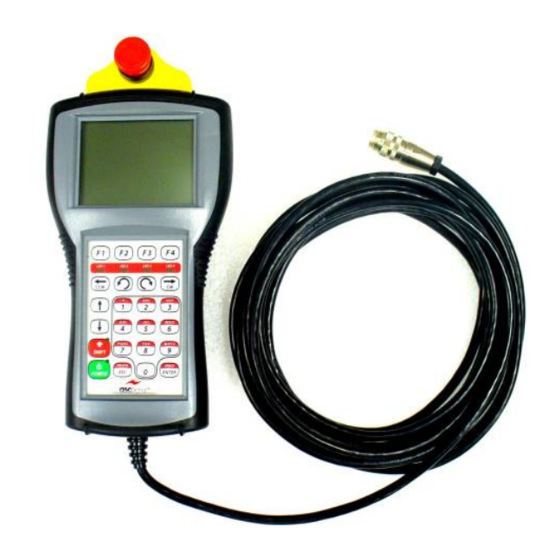
1.0 Operation of Handheld Controller The NGC-ODU may be controlled from the pedestal base, via use of the Handheld Controller (shown below in Figure 1-1). Figure 1-1: Handheld Controller with Connection Cable The Handheld Controller is QTERM-G55 model controller with a 320x240 pixel, LCD transflective FSTN, grayscale (16 shades) display. -
Page 11: Handheld-To-Odu Connection
DO NOT LEAVE HANDHELD SCREEN IN DIRECT SUNLIGHT! Screensaver does not protect screen from sunlight. Prolonged exposure to sunlight will cause screen to become temporarily washed out, making it unusable until returned to shade for a time. If exposed for too long, such as an entire day, screen may be permanently damaged. The screen saver becomes active: ... -
Page 12: Handheld Keypad Breakdown
1.2 Handheld Keypad Breakdown Figure 1-2: Handheld Keypad Image Button Title Function/Description Standby power button for handheld (does not affect power to NGC-ODU) POWER BUTTON (ON/OFF) NOTE: If power to Handheld Controller is turned OFF, the system will return to “Local Mode” with the IDU in control of the system. -
Page 13: Handheld Screens Breakdown
1.3 Handheld Screens Breakdown The following diagram illustrates the General Menu Tree, meaning the order of screens/pages for the NGC‐ODU Handheld Controller. Figure 1-3: Handheld Controller Menu/Screen Tree While navigating the screens of the Handheld Controller, you may notice certain icons, graphical conventions, or occurrences related to navigation and editing of certain fields. In the below table (Table 1.1), these are illustrated and explained. -
Page 14: Figure 1-4A: Home Screen
1.3.1 General User Screens This section explains handheld interface screens available to non-privileged users, meaning general (unqualified) personnel. For screens meant for qualified technical personnel, refer to Section 1.3.2. If you are a General User, DO NOT use this manual. General users should refer to manual #7581776. 1. -
Page 15: Figure 1-5: Jog Screen
2. Jog [Main Dish] SCREEN The JOG SCREEN (see Figure 1-5 and related table) is used to move the antenna. This screen can be used to jog any axis, as well as to see angle feedback from the encoders or resolvers, and to view any faults or alarm conditions. -
Page 16: Figure 1-6: Goto Screen
3. GoTo SCREEN The GoTo SCREEN (Figure 1-6), same as the JOG SCREEN, may also be used to move the antenna. However, this screen is more precise and less labor intensive than the JOG SCREEN. With the GoTo SCREEN, the user can edit the Az, El, and/or Pol fields, as well as command/execute antenna movement with the GoTo AZ, EL, POL soft-key (F4). -
Page 17: Figure 1-7A: Parameters Screen
4. Parameters SCREENS & PAGES The Handheld controller has dozens of screens which allow the advanced user to view almost all of the NGC-ODU’s configuration parameters. The basic user, however, is authorized to view only a handful of these parameters. This section provides you with some representative examples. -
Page 18: Figure 1-7B: Parameters Screen (Edit Mode)
Figure 1-7b: Parameters Screen (Edit Mode) Figure 1-7c: Button Ribbon Options, Parameters Edit Mode 2 Number Description Jump to a different Parameter page by inputting page # and pressing ENTER F1: Move cursor back to delete (works the same as backspace key on a computer keyboard) F2: Move cursor to the beginning/HOME of a selected field F3: Move cursor to the END of a selected field F4: Go to next Button Ribbon for MORE options (see Figure 1-7c) -
Page 19: Figure 1-8A: Current Faults
5. Current Faults SCREEN The CURRENT FAULTS SCREEN (Figure 1-8a) provides a list of all active faults the NGC-ODU might have. Take note that any faults associated with the NGC-IDU will not be listed in this manual. Refer to Appendix A (Table A.2) for a list of Faults and their meanings Path: HOME SCREEN ->... -
Page 20: Figure 1-9: Message Log
6. Message Log SCREEN The MESSAGE LOG SCREEN (Figure 1-9) can be used to view a list of historical pop-up messages going back to the last time power was applied to the Handheld controller. Path: HOME SCREEN -> F4 (MORE) -> F1 (MESSAGE LOG) Figure 1-9: Message Log Number Description... -
Page 21: Figure 1-10: Installation Screen
7. Installation SCREENS The INSTALLATION SCREENS (Figure 1-10) provide users with a way to go through the setup interview process, on a parameter-by-parameter basis, allowing them to configure the most common parameters used by the system. Path: HOME SCREEN -> F4 (MORE) -> F2 (INSTALLATION) Figure 1-10: Installation Screen Number Description... -
Page 22: Figure 1-11: Diagnostic Commands Screen
8. Diagnostic Commands SCREEN The DIAGNOSTIC COMMANDS (Figure 1-11) screen provides users with a way to access and input certain advanced diagnostic functions. Refer to Appendix C (Table C.30) for a detailed list of Diagnostic Commands. Path: HOME SCREEN -> F4 (MORE) -> F3 (DIAGNOSTIC CMDS) Figure 1-11: Diagnostic Commands Screen Number Description... -
Page 23: Figure 1-12A: Password Screen
9. Password SCREEN The PASSWORD SCREEN (Figure 1-12a) allows the user to both enter and exit the installer mode (see passwords section at the beginning of 1.0 for more detailed information). Path: HOME SCREEN -> F4 (MORE) -> F4 (MORE) -> F1 (PASSWORD) ... -
Page 24: Figure 1-13: Edit Fraction Screen
10. System Information (SYSINFO) SCREEN NOTE: this screen may appear strange. This is because the data on the screen has a formatting issue with the screen’s resolution. The SYSINFO SCREEN allows the user to view general information about the system, such as the software type/version, time/date, current temperature/weather conditions, sound/audio settings, etc. -
Page 25: Figure 1-14A: Search Screen
2. Search SCREEN The SEARCH screen (Figure 1-14a) allows you to browse/search for and jump to (once selected) a particular screen, page, or item within the system. Path: HOME SCREEN -> F2 (PARAMETERS) -> F4 (SHORTCUTS) -> F3 (SEARCH) Figure 1-14a: Search Screen ... -
Page 26: Figure 1-14C: Search Screen With Open Dropdown Menu
Figure 1-14c: Search Screen with Open Dropdown Menu Number Description Opened DROPDOWN Menu display. Pressing ENTER key for a selected item/page will allow you to JUMP to that item/page. F1: Navigate DOWN by 1 page in DROPDOWN Menu F2: Navigate UP by 1 page in DROPDOWN Menu ... - Page 27 3. Faults SCREENS These screens give detailed lists of problems or events currently seen, latched since last clearing event, and alarms cut off (in other words, acknowledged and masked). See Appendix A (Table A.2) for faults. Path: HOME SCREEN -> F2 (PARAMETERS) -> (see SEARCH or SHORTCUTS page for current Page #) ...
-
Page 28: Figure 1-15: Voltage Monitor Mask (Bitmask Edit Screen)
16. Command Bits SCREENS (Cmd Bits, Az & El) This screen is for ASC Signal use only. ... -
Page 29: Figure 1-16: Shortcuts Screen
1.3.3 Shortcuts You can use the Shortcuts feature to quickly find a particular Parameter Screen by pressing the soft key labeled “Shortcuts” [F4] from the Parameter Screen. The Shortcuts are displayed on multiple pages. Press F4 again to display the next Shortcut page as necessary. When you’ve located the desired Parameter Screen in the list of shortcuts, enter the corresponding page number in the “Jump to Page”... -
Page 30: Odu System & Parts Overview
2.0 ODU System & Parts Overview 2.1 ODU with Parts Numbered 14 15 Figure 2-1: NGC Outdoor Unit You may need to refer back to Figure 2-1 (for numbers) as you review the following sections. 7580368_Rev D Page 29 of 89... -
Page 31: Odu Connectors & Cable Glands
TABLE 2.1: NGC Outdoor Unit Parts List (Compare to Figure 2-1) Number Part Description Reference Paragraph Master Controller (MC-7) El ACU: Elevation Axis Control Unit El ASU: Elevation Axis Sending Unit Az ACU: Azimuth Axis Control Unit Az ASU: Azimuth Axis Sending Unit Pol ACU: Polarization Axis Control Unit (OPTION) Pol ASU: Polarization Axis Sending Unit (OPTION) El VFD: Elevation Variable Frequency Drive... -
Page 32: A1 Master Controller (Mc-7)
TABLE 2.2: ODU Connectors & Cable Glands Connector or Gland Part/Name Purpose NGC bus OUT NGC bus IN HANDHELD CONNECTION JACK J3 & tethered plug Connection to the NGC-IDU Fiber Elevation angle feedback El Position Resolver Elevation limits feedback El Limits Azimuth angle feedback Az Position Resolver Azimuth limits feedback... - Page 33 Internal NGC bus 5: Connection to ASU, ACU, etc. Internal NGC bus 3: Connection to ASU, ACU, etc. Internal NGC bus 4: Connection to ASU, ACU, etc. Handheld Terminal Connector: Connects Handheld-to-ODU through the jack Customer ESTOP: Allows customer/integrator to add custom relay or switch to ESTOP chain. Circuit must be completed for system to operate, so it’s factory supplied with jumper plug ODU ESTOP: Factory-wired to chassis ESTOP switch TABLE 2.3: MC-7 PWA Front Edge Indicator LEDs and Display...
-
Page 34: Mc-7 Switches
Handheld terminal connector USB slave device connector Factory use only Factory use only Expansion I/O (ASC Signal use only) NGC bus monitor (RS-485 levels) Factory use only Power supply monitoring jumpers (Factory installed) AS-1 (compass/GPS) interface. NOT USED in this application 100BaseFX optical transceiver with integral ST jacks. -
Page 35: A2/A4/(Option) A6 Axis Control Units (Acu)
2.4 A2/A4/(OPTION) A6 Axis Control Units (ACU) An Axis Control Unit (ACU) is a device which provides loop closure by driving a motor (often through a VFD or other motor controller) in response to angular feedback and limit conditions from an Axis Sending Unit (ASU) There are five roles an ACU can assume: Azimuth Control Unit (for a single axis), Elevation Control Unit, Polarization Control Unit, and, in dual-motorized azimuth systems where there will be two ACUs acting in concert, Azimuth CCW Control Unit and Azimuth CW Control Unit. -
Page 36: Axis Control Unit Pwa Indicator Leds Description
TABLE 2.10: Axis Control Unit PWA Indicator LEDs Description Display # Function GREEN +3.3V power. ON = +3.3V power on the card is good GREEN +12V P/S. ON = A10 (Pri P/S) PS2 on and operating GREEN USB Link. ON = USB bus power OK YELLOW USB Connect. -
Page 37: A3/A5/(Option) A7 Axis Sending Units (Asu)
TABLE 2.14: ACU Test Points Part Function Modbus TX (TTL) +3.3VDC power Modbus RX (TTL) Digital ground (GND) Velocity control voltage (0-3.3V, Az G7 VFDs only) Factory use only Reset line NGC bus ground/return NGC bus transmit enable TP10 -12VDC power voltage TP11 Factory use only TP12... -
Page 38: Axis Sending Unit Pwa Front Edge Indicator Leds & Display
TABLE 2.15: Axis Sending Unit PWA Front Edge Indicator LEDs & Display Display # Name DS11 NONE NOT USED DS10 (NOT USED IN Az & Pol) AMBER EL LOW NONE NOT USED NONE NOT USED NONE NOT USED NONE NOT USED NONE NOT USED DS4 (CW Limit in Az &... -
Page 39: Asu Switches
Factory use only Serial encoder interface (SSI bus) NGC bus JTAG port NGC bus Limit switch input Spare inputs/outputs (ASC Signal use only) Factory use only Factory use only NGC bus monitor (RS-485 levels) TABLE 2.18: ASU Switches Part Function Reset switch 16-position rotary switch. -
Page 40: A8/A9 El/Az Vfd
A5 Az ASU: The Az ASU receives sensor data from: NOTE: the NGC does not use EAST/WEST in calculating Az, ONLY Az Clockwise/Counterclockwise Clockwise (CW) and Counter-Clockwise (CCW) limit switches Analog Resolver signals OPTION: A7 Pol ASU: The Pol ASU receives sensor data from the following locations: ... -
Page 41: Vfd Sizes
The following table defines the different Variable Frequency Drive (VFD) sizes that are utilized by the four variants of the NGC-ODU. Note that all of the below VFDs are manufactured by the Yaskawa Electric Corporation. TABLE 2.22: VFD Sizes NGC-ODU ASC Signal Yaskawa P/N Horsepower Input Voltage Rate Output Model Current... - Page 42 The following table provides a list of the VFD parameters that are programmed differently from the manufacturer’s default setting. Values are shown for both 208 and 380 VAC ODUs. The only parameter that is specific to the antenna and must be set at the time of installation is the Motor Rated Current parameter (see E2-01).
-
Page 43: A10 Power Supply Board
Value for Value for Parameter Name Description NGC-ODU- NGC-ODU- 208-x 380-x Determines function of VFD terminal P1 (open-collector Terminal P1 output). Value 6 sets terminal P1 to function as a “Drive H2-02 Function Selection Ready” output. Used to indicate to ACU board that the VFD is ready to operate and no VFD faults are present. -
Page 44: Miscellaneous Parts Descriptions
TABLE 2.25: A10 P/Ns & Specifications ASC Signal XP Power P/N Input Voltage Output Voltage Output Current Output Power Designation 7579729 ECM14US24 80-264 VAC 24 VDC 5 Amps 120 Watts 7579730 ECM40US12 90-264 VAC 12 VDC 3.5 Amps 40 Watts... -
Page 45: Terminal Blocks (Tb1-Tb4)
NGC Bus Cables: NGC Bus cables and connectors pin-out by pin number: TABLE 2.26: NGC Bus Cable Pin-Out Pin # Name Purpose +12V DC nominal LOGIC -12V DC nominal LOGIC Ground DC Return MOTOR +24V MOTOR (DC) -24V MOTOR (DC) Ground DC return LOGIC Telemetry Bus A... -
Page 46: A13 External Wiring Interface (Ewi)-1
Technical Power Input – Phase #1 TB1-2 Technical Power Input – Phase #2 2.10 A13 External Wiring Interface (EWI)-1 EWI-1 is used on the following NGC-ODU systems: NGC-ODU-208-3 NGC-ODU-208-5 NGC-ODU-380-3 NGC-ODU-380-5 Refer to page 47 for an example. Figure 2-7: External Wiring Interface ... -
Page 47: Ewi-1 J3 Pin-Out
2.10.2 EWI-1 J1/J4/J6 Elevation/Azimuth/Polarization Resolver Connectors The J1, J4, and J6 connectors of the EWI-1 are designed to connect to a cable connected to a standard Size 11 resolver. During installation the installer will terminate the wires to the pluggable terminal blocks. Table 2.32: EWI-1 J1/J4/J6 Pin-out Function Mating wire color... -
Page 48: A13 External Wiring Interface (Ewi)-2
NGC-ODU-380-5-HA NGC ODU, 380 VAC, 5HP, HIGH ACCURACY In these systems, the EWI-2 is a factory replacement for the EWI-1. Note also that the cabinet wiring from J8 and J10 to the ASU-2s will be different than in the NGC-ODU-208-3, NGC-ODU-208-5, NGC-ODU-380-3, and NGC-ODU-380-5. -
Page 49: Ew2-1 J6 Pin-Out
Table 2.37: EWI-2 Connectors Function Connector Type Notes Elevation Encoder Pluggable terminal block Customer terminates mating connector Elevation hard limits Pluggable terminal block Customer terminates mating connector Low Elevation Pluggable terminal block Optional. Customer terminates mating connector Azimuth Encoder Pluggable terminal block Customer terminates mating connector Azimuth Limits Pluggable terminal block... -
Page 50: Ewi-2 J3 Pin-Out
Table 2.40: EWI-2 J3 Pin-out Pin Function Mating wire color Low Elevation Status (varies) Low Elevation common (varies) 2.11.4 EWI-2 J5 Azimuth Hard Limit Connector The J5 connector of EWI-2 is designed to connect to a cable connected to a limit switch. -
Page 51: Odu System & Parts Troubleshooting
3.0 ODU System & Parts Troubleshooting While performing circuit tracing & analysis, refer to 7579836 (208VAC) or 7579837 (380VAC) to drill down to faulty Field Replaceable Unit (FRU) [list is in Section 5.0: NGC Antenna Controller Unit Spares Kits] Steps MUST be performed by qualified technical personnel! Danger of serious injury or death from electrical shock! 3.1 Antenna JOG/Movement Issues ... -
Page 52: Figure 3.1C: Troubleshooting Flowchart #1C
Figure 3.1c: Troubleshooting Flowchart #1c Check to see if you have a motorized SRT. You may be moving the SRT rather than the main antenna. Note that in some NGC-ODUs, Do displayed Az & Ell Antenna won’t JOG any Axis (Az & El) still change? an indeterminate SRT setting can cause the system to try to move the SRT instead. -
Page 53: Figure 3.3: Troubleshooting Flowchart #3
One axis (Az or El) will NOT move For Az, Ensure motors ensure CW Check all control are strapped soft limit is electrical for the proper greater than connections in Ensure axis Check voltage. CCW soft NGC-ODU Ensure ALL Ensure ACU &... -
Page 54: Directional/Axis Issues
Figure 3.5: Troubleshooting Flowchart #5 3.2 Directional/Axis Issues Az and/or El movement direction Do Az & El display the proper values for their correct directions? Move to next flowchart Check the encoder invert setting Reset Are you in properly and Invert setting Southern recalibrate... -
Page 55: Figure 3.7: Troubleshooting Flowchart #7
Figure 3.7: Troubleshooting Flowchart #7 Figure 3.8: Troubleshooting Flowchart #8 7580368_Rev D Page 54 of 89... -
Page 56: Figure 3.9: Troubleshooting Flowchart #9
Figure 3.9: Troubleshooting Flowchart #9 Antenna oscillates excessively when commanded to move after reaching final location Check resolver Deadband too wiring for poor Are Motorization small for antenna grounding or other parameters and/or Motorization sources of noise, correct? parameters? such as routing too close to motors. -
Page 57: Movement & Wiring Troubleshooting Scenarios/Solutions
Figure 3.11: Troubleshooting Flowchart #11 Movement & Wiring Troubleshooting Scenarios/Solutions Scenario 1: The Azimuth and/or Elevation won’t go to input position when commanded (or moves unnecessarily slow once commanded), but it will still manual jog normally. Solution: Check motorization parameters such a maximum speed and proportional gain (Kp) for correct values. -
Page 58: Other Pol Troubleshooting Scenarios/Solutions
Polarization axis moves in the correct direction, but times out too quickly Does motor or resolver Move to Is axis timeout connection have too much next setting too short? flowchart “play”? Check motor drive connection for excessive Increase axis backlash. Check resolver/encoder coupling for timeout setting. -
Page 59: Other Troubleshooting Scenarios
Scenario 5: Polarization axis moves, but displayed values go the wrong way Solution: Check encoder/resolver invert setting (Do not attempt to correct improper direction by changing invert.) Scenario 6: Polarization axis oscillates excessively when commanded to move after reaching final location. ... -
Page 60: Cleaning, Inspections, & Maintenance
4.0 Cleaning, Inspections, & Maintenance This section contains periodic preventive maintenance instructions for the NGC Antenna Controller Outdoor Unit. Provided in this section are inspection and preventive maintenance procedures including cleaning, lubrication and painting procedures deemed within the capabilities of the average station technician. Refer to the applicable vendor manuals for any repair procedures not included in this section. -
Page 61: Inspections
4.2 Inspections The frequency of inspection is contingent upon the operational environment in which the antenna is located. A visual inspection of the antenna components should be performed at least monthly. Where there are no established wear limits, perform a visual inspection to locate worn or damaged parts which could cause improper functioning of the Antenna. -
Page 62: Presence Of Moisture/Water
Remove all power to the system, do what you can to ensure ODU is able to dry out, and (most importantly) contact ASC SIGNAL TECH SUPPORT immediately (see Appendix D). If large amounts of water get into the ODU box, it can cause permanent damage, and replacement of the entire NGC-ODU will likely be necessary. -
Page 63: Ngc-Odu Spare Kits
5.0 NGC-ODU Spare Kits Below is the list of spares kits available to support the maintenance of the NGC ODU system. Refer to the instructions supplied with each kit for the exact procedure to be performed in the replacement for each. 5.1 VFDs All VFD Spares kits include Modbus and ACU Interface cables. -
Page 64: Circuit Breakers
5.6 Circuit Breakers NGC-SPR-BKR-20-3: 3-Pol 20 Amp – Used in 380VAC ODU NGC-SPR-BKR-30-3: 3-Pol 30 Amp – Used in 208VAC ODU NGC-SPR-BKR-20-2: 2-Pol 20 Amp–Used in both 208VAC and 380VAC ODU NGC-SPR-BKR-3-1: 3-Amp Wago Supplementary Breaker–1 each to protect Primary PS, K1 SSR, & Pol Interface ... -
Page 65: Appendix A: Pwa Display Codes & Ngc-Odu Faults Glossary
APPENDIX A: PWA Display Codes & NGC-ODU Faults Glossary The seven segment display on each of the PWAs is used to communicate status and error code messages to the user. On power up or reset, the display on each PWA will show the build ID of the current software in a 2 cycle sequence. - Page 66 TABLE A.2: Faults Glossary Alarm/Fault/Event Meaning Action Required AC (Mains) Voltage Error Power outside of expected parameters Check 3 Phase AC power Az Antenna Control Unit Az ACU off bus or has a major problem Check Az ACU PWA & associated wiring Az Antenna Control Unit 2 Az ACU 2 off bus or has major problem.
- Page 67 IDU Undertemp IDU reports under Temp Reported by IDU Interfacility Link Failure (Cannot be reported) Reported by IDU Loss of Config Data IDU reports coming loss of data from full disk drive Reported by IDU Low El Low El switch is closed No action required Low Signal Alarm IDU reports low signal alarm...
-
Page 68: Appendix B: Theory Of Operation
APPENDIX B: Theory of Operation Mains Thermostat Heater Power PMIA* NGC-IDU Mains Power MOTOR K3-SSR K4-SSR BRAKE Resolver POL Limit Switches Mains Power MOTOR MC-7 Low El Switch Resolver EL Limit Switch Mains Power MOTOR A10 P/S PS1: +24 VDC PS2: +12 VDC PS3: -12 VDC Resolver... -
Page 69: Figure B-2: Ngc Antenna Control System Block Diagram
Figure B-2: NGC Antenna Control System Block Diagram B.1 Role of the NGC-ODU in the System The division of responsibilities between the NGC-ODU and the NGC-IDU is fairly simple. The NGC-ODU is fundamentally responsible for pointing the antenna. The NGC-IDU is responsible for determining where the antenna should be pointing. - Page 70 “Fixed” Operational Configuration (1) is the “standard” configuration where the NGC is interfaced to a normal, elevation-over-azimuth pedestal. “Mobile” Operational Configuration (2) is used with ASC Signal Standard Profile and Low Profile Positioners. It differs from the Fixed (1) configuration as follows: ...
- Page 71 B.5.1 Angular Feedback Angular feedback may come from a variety of devices, including sin-cos resolvers and several types of optical encoders. Consult your data sheet for details. Resolver feedback is oversampled and averaged by the ASU-2 to lower the noise amplitude. This has the effect of giving what seems to be increased apparent resolution, but the resolver-to-digital interface is still a 16-bit device so the true resolution remains at 0.0055 degrees.
- Page 72 The final sum is ‘collared’ by clamping at a maximum rate and a minimum rate. The maximum rate, obviously, is necessary because of the range of the drive signal. The minimum rate, combined with the programmable dead band, is used to make the antenna quiet down once it gets into the range where resolver/encoder noise is significant.
- Page 73 serves as a form of backup position sensing. (The potentiometer also serves as an effective travel limit sensor, eliminating the need for separate limit switches.) The DC stepper motor can drive the actuation drive screw directly, without the need for reduction gearing. The DC stepper motors are selected from standard NEMA form factors for such motors, allowing for multiple supply sourcing.
-
Page 74: Appendix C: Glossary Tables
APPENDIX C: Glossary Tables This section lists all handheld terminal parameters in alphabetical order. Each parameter is accompanied by a description of the function, the range (or cross-reference), whether or not it is configurable, and the option (if any) with which it is associated. Abbreviations Key = Azimuth = Elevation... - Page 75 Parameter Name Function Units & Range Config Option VFD parameter indicating the maximum sustained current Amperes, Az Motor Rated that should be generated for the Az motor. Consult 0 to 20.0 Current installation drawing for motor kit for correct value. Permissible time limit for temporary Az axis overcurrent Seconds, Az Overcurrent...
- Page 76 Parameter Name Function Units & Range Config Option Current platform Pol reported by Pol Sending Unit Degrees, Current Plat Pol -360 to 360 Current global Pol calculated from platform angles, attitude, Degrees, Current Pol & SRT position. -180 to 360 Index into working set of current satellite in IDU 0 to 63 Current Sat ID...
- Page 77 This field allows the advanced user to disable the use of See Table C.14 Limit Switch any or all limit switch inputs. This is used for nonstandard Mask configurations & should not be set without ASC signal direction. Commanding presence indication See Table C.15 Local Remote...
- Page 78 Parameter Name Function Units & Range Config Option Time delay before 12VDC or -12VDC alarm signals. Allows Seconds, ODU 12V Trip system to avoid signaling false power supply alarms during 0 To 30 Delay startup inrush. Measured voltage of -12VDC power supply, approximately Volts ODU Minus 12V Allowable error in -12VDC power supply before alarm...
- Page 79 Parameter Name Function Units & Range Config Option Distance from target platform Pol that NGC cuts power to Degrees, Pol CW Coast pol motor in the CW direction 0 to 1 Drive Software limit, which is the maximum legal value of Degrees, Pol CW Plat SW Current Platform Pol.
- Page 80 Parameter Name Function Units & Range Config Option Commanded up-&-down offset of SRT Degrees SRT Target Y Delta Commanded in-&-out offset of SRT Inches SRT Target Z Delta Reported Temp of SRT PWAs in SRT drive. May not be Degrees, C SRT Temp used in this system.
- Page 81 Parameter Name Function Units & Range Config Option Number of VFDs 2 (az, el) VFD Count 3 (az1, az2, el) Modbus link status for El VFD See Table C.29 VFD El DataLink Status Summary of drive status for El VFD See VFD manual VFD El Drive Status...
- Page 82 Standard sin/cos resolvers. Normal setting for most antennas. Almost always correct setting Resolver unless system is different ASC Signal assembly 7543381 (not supported in current release of For future use only Resolver 18-to-1 software) Table C.3: Axis Limit Conditions, Azimuth, Polarization, & SRT X axes These are limit conditions commonly reported by the NGC-ODU for axes with clockwise and counterclockwise directions.
- Page 83 Table C.5: Supplementary azimuth axis inputs These are extra inputs to the azimuth axis that can be used with customized installations of the NGC-ODU. For a typical fixed antenna, none of these are used. Value Meaning Comment Axis interlock input is active. Not used in this system presently. Not used Axis Interlock Counterclockwise sector switch active.
- Page 84 Table C.10: Compass Faults These are the compass faults that may be reported. Value Meaning Comment No device present, option not selected ---- Compass not provisioned Normal state is no AS-1 is installed. Compass is normal. Optional. Data received from compass data from compass Compass is not responding.
- Page 85 Table C.15: Local Remote settings These are the values for local/remote. Value Meaning Comment TPU or Remote TPU has control Local SNMP Agent or M&C port has control Remote Handheld terminal has control Local handheld Value out of range Field not updated ---- Table C.16: Axis Movement Faults These are the axis movement faults that can be reported.
- Page 86 Table C.18: Voltage Monitor Mask values Since there are several possible power supply configurations, the NGC-ODU has a configuration field to deal with variations without generating spurious alarms. Value Meaning Comment Ignore -12VDC monitoring (recommended if no resolvers Minus 12V A are present in system) Not used Future redundant power supply option...
- Page 87 Table C.23: SRT Movement Command This field gives access to the SRT diagnostic and maintenance commands. Value Meaning Comment Default state Optional No operation Lock all SRT axes Optional Lock XYZ Unlock all locked axes Optional Resume automatic Recalibrate SRT. Warning: this moves SRT to all limits of operation. Optional Recalibrate Check SRT for functionality without disturbing position more than slight amount...
- Page 88 Table C.27: Track Mode enumeration These are merely reported by the NGC-ODU from data supplied by the NGC-IDU. Value Meaning Comment No data from NGC-IDU ---- Value out of range NGC-IDU reports interpolative tracking is selected Adaptive cont step NGC-IDU reports Intelsat tracking is selected Intelsat NGC-IDU reports Intelsat tracking with peak optimization is selected Intelsat adaptive...
- Page 89 Table C.30: Diagnostic Commands Command Purpose Consequences Send all software revisions to handheld None Request All Rev Nums (10) Calibrate inclinometer in AS-1 assuming Can damage pointing accuracy in Pitch Roll Zero Level (25) platform is level and azimuth axis is mobile systems if incorrectly used.
-
Page 90: Appendix D: Equipment Issues & Tech Support
ASC Signal strives to ensure all items arrive safe and in working order. Despite these efforts, equipment is at times received with damage or faults. When this occurs, it may be necessary to return some items to ASC Signal for either repair or replacement.
Need help?
Do you have a question about the NGC-ODU-208-3 and is the answer not in the manual?
Questions and answers