Table of Contents
Advertisement
Quick Links
Advertisement
Table of Contents

Related Manuals for MUSCLE Corporation Cool Muscle 3

Summary of Contents for MUSCLE Corporation Cool Muscle 3
- Page 1 I/O Type User's Guide MDUG-CM3/20831E-11 CM3 Firmware Version v1.01...
- Page 2 Direct type, I/O type, and Pulse type CM3 has three sorts of control types: I/O type This user's guide is for the CM3 only. The control type of CM3 can be changed according to the control method. Type can be changed from the dedicated software “COOL WORKS QUICK” . •...
-
Page 3: Table Of Contents
Table of Contents CM3 I/O Type User's Guide Before Use ..................4 Instructions for Safety ............... 5 Chapter 8 Various Functions..........45 Chapter 1 Functions and Structure ........8 8.1ᅠSequence When Power is On ............45 1.1ᅠOverview .....................8 8.2ᅠSequence to Reset Alarm ............. 46 1.2ᅠProduct Code Scheme ..............9 8.3ᅠPositioning Operation .............. -
Page 4: Before Use
• This User's Guide is only intended to provide information about the product and does not guarantee any results from usage of the product. MUSCLE CORPORATION is not responsible for any damages and/or injuries resulting from the implementation in accordance with the contents of this User's Guide. -
Page 5: Instructions For Safety
Instructions for Safety Instructions for Safety Be sure to read before use for safety ⃞ To ensure safe use To ensure the safe and proper use of our products, it is important that you read this User's Guide thoroughly prior to its use. Failure to read, fully understand and implement following instructions and precautions may result in damage to the product, the machine to which it is installed, or operator injury. - Page 6 Instructions for Safety Warning Caution (Transportation) Never touch the rotating part of the motor while The product is precision mechanical equipment. operating. Do not drop or give any strong impact to the product. The failure could result in damages or malfunction. The failure could result in injuries.
- Page 7 Do not change the parameter settings excessively. The failure could result in instable or unexpected operation. MUSCLE CORPORATION is not responsible for any damages resulting from modifications or repairs made to the product. ⃞ About processing of waste This product should be treated as an industrial waste when it is disposed.
-
Page 8: Chapter 1 Functions And Structure
Chapter 1 Functions and Structure Chapter 1 Functions and Structure 1.1 Overview The "CM3" is an integrated AC servo system with a built-in, encoder, driver and controller. The higher torque and speed have been achieved by MUSCLE's own control technology. With MUSCLE's own programming language “CML”... -
Page 9: ᅠProduct Code Scheme
Chapter 1 Functions and Structure 1 . 2 Product Code Scheme CM3's product code scheme is described as below. C M3 - 17 L5 0A ⃞ Product Name Product Name Product Code CM3 42mm Short CM3-17S50A CM3 42mm Long CM3-17L50A CM3 56mm Short CM3-23S50A CM3 56mm Long CM3-23L50A... -
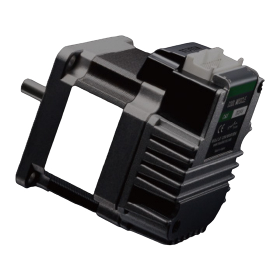
Page 10: ᅠParts Description
Chapter 1 Functions and Structure 1 . 4 Parts Description The names of parts of CM3 are as shown below. Main Connector Motor Mounting Holes (4 corners) Flange Driver Case Status LED Displays the motor status with LED blinking patterns Output Shaft Rabbet *... -
Page 11: ᅠControl
Chapter 1 Functions and Structure 1 . 6 Control The I/O type CM3 can select and execute up to 8 points of Motion Data set from the PC by input signals. Each Motion Data is composed of necessary items for motion such as speed, acceleration, target position, etc. Refer to "Chapter 8 Various Functions"... -
Page 12: Chapter 2 Installation
Chapter 2 Installation Chapter 2 Installation 2.1 Mounting to Machinery CM3 can be mounted either horizontally or vertically. Mount CM3 on the smooth and rigid surface of a metal plate. When installing CM3, insert the rabbet located on the motor's installation surface into the mounting plate's counterbore or through holes then screw it with four bolts through the four mounting holes on CM3's installing surface leaving no gaps between the surface and metal plate. - Page 13 Chapter 2 Installation When a pulley is directly mounted onto output shaft, radial force (Fr) will be produced by belt tension and may result in damaging bearings in a motor. When a gear is directly mounted onto output shaft, smaller the dimensions of gear, bigger radial force (Fr) will be produced and may result in damaging bearings in a motor.
-
Page 14: Chapter 3 Wiring And Connection
Chapter 3 Wiring and Connection Chapter 3 Wiring and Connection 3.1 Typical Connection Example ⃞ Caution about Cabling • Be sure that the power is off before plugging or unplugging connectors. • Pay attention for straight insertion and removal of connectors by holding connector's body. •... -
Page 15: ᅠConnector Pin Layout And Functions
Chapter 3 Wiring and Connection 3 . 2 Connector Pin Layout and Functions Pin layout and functions of CM3 cables are described below. ⃞ Main Connector CM3 has a 24-pin connector on the top. The pin layout, names and functions are as follows. Name Function Name... - Page 16 Chapter 3 Wiring and Connection ⃞ Communication Cable A(1000mm, 2000mm, 3000mm, 5000mm) Product Number: CMRSA1-****W(****: Cable Length) Wires: AWG26 UL1007 (80℃ / 300V) XARR-03VF (JST) XM3D-0921 (Omron) CM3 side PC side Color Name Function Color Name Function RS232C Receive Data from PC RS232C Receive Data from CM3 RS232C Transmit Data from PC RS232C Transmit Data from CM3...
-
Page 17: ᅠElectrical Specifications
Chapter 3 Wiring and Connection ⃞ Power Cable A (1000mm, 3000mm, 5000mm) Product Number: CM3PWA1-****S (****: Cable Length) Wires: AWG24 UL758 Style2464 (80℃ / 300V) XADRP-08V (JST) Color Name Function Color Name Function POWER +24Vdc POWER +24Vdc P-GND Power Ground P-GND Power Ground STO_IN+ STO Input +... -
Page 18: ᅠInput/Output Circuit
Chapter 3 Wiring and Connection 3 . 4 Input/Output Circuit IN_COM 12kΩ IN1, 2, 3, 4 No Polarity IN1, 2, 3, 4 3.6kΩ IN5+ SCHOTTKY-D IN6+ IN5, IN6 Input With Polarity IN5- IN6- STO+ 12kΩ No Polarity STO- 3.6kΩ +5~24Vdc OUT1 OUT2 OUT3 OUT1, 2, 3... -
Page 19: ᅠCircuit Connection
Chapter 3 Wiring and Connection 3 . 5 Circuit Connection ⃞ Connection Example with Sink Output Circuit Controller I/O Cable IN_COM 12kΩ 3.6kΩ 12kΩ 3.6kΩ 12kΩ 3.6kΩ 12kΩ 3.6kΩ IN5 + IN5 - IN6 + IN6 - OUT1 OUT2 OUT3 ALARM D_GND Power Cable STO+... - Page 20 Chapter 3 Wiring and Connection ⃞ Connection Example with Source Output Circuit Controller I/O Cable IN_COM 12kΩ 3.6kΩ 12kΩ 3.6kΩ 12kΩ 3.6kΩ 12kΩ 3.6kΩ IN5 + IN5 - IN6 + IN6 - OUT1 OUT2 OUT3 ALARM D_GND Power Cable STO+ 12kΩ STO- 3.6kΩ...
-
Page 21: Chapter 4 Input/Output
Chapter 4 Input/Output Chapter 4 Input/Output 4.1 Input Signal 4.1.1ᅠInput Filter CM3 has 6 Inputs in total, 4 digital inputs, IN1 to IN4, do not come with polarity and 2 digital inputs, IN5 and IN6, with polarity. Filter function (1 to 50 msec) by software is available on all inputs. The filter function by software cannot be removed. -
Page 22: ᅠOutput Signal
Chapter 4 Input/Output 4 . 2 Output Signal INPUT 4.2.1ᅠOutput Function System CM3 has 4 outputs that are an open-drain circuit. OUT4 is fixed for Alarm Output and other Outputs (OUT1 to OUT3) can be set as ABZ Output or General Output by parameters. OUTPUT ABZ output User Defined... -
Page 23: Chapter 5 Communication Functions
COOL WORKS QUICK (hereafter CWQ) is CML compatible utility software, has user-friendly interface and assists easy operation of CM3. With CWQ, you can easily set and save parameters and data, stream data in graph and etc. The latest version of CWQ and its manual are available for free on MUSCLE CORPORATION's website. (https:/ /musclecorp.com/motion-en) -
Page 24: ᅠChange Control Type
Chapter 5 Communication Functions 5 . 2 Select Control Type Once communication is established, then select the control type. The control type can be selected from the initial setup wizard. Click the button below to open the Initial Setup Wizard. Start Initial Setting Wizard The Initial Wizard allows you to change the control type and... -
Page 25: Chapter 6 Cml(Cool Muscle Language
Chapter 6 CML (COOL MUSCLE Language) Chapter 6 CML(COOL MUSCLE Language) 6.1 Overview The programming language CML via RS-232C serial communication can control CM3. MUSCLE developed CML based on ASCII code that is the most modern character-encoding schemes used for computer and communication devices. ASCII code chart is as shown in the below table. ⃞... - Page 26 Chapter 6 CML (COOL MUSCLE Language) CML is composed of parameter, Motion Data, execution command and Query command. CML and character codes are shown in the below table. CML Command Character Code Function Others Motion Environmental Parameters K1 - K15 Origin Detection Parameters K22 - K30 Gain Adjustment Parameters K31 - K36...
-
Page 27: ᅠParameter Settings
Chapter 6 CML (COOL MUSCLE Language) 6 . 2 Parameter Settings Set parameters such as Resolution, communication settings, and protection function. Details of various functions and usage examples are described in Chapter The format for setting/checking using CML parameters is as follows. ⃞... - Page 28 Chapter 6 CML (COOL MUSCLE Language) 6.2.1ᅠMotion Environmental Parameters Name Setting/Range Unit Restart Reference/Remarks Set the pulse count per revolution. The 1000 Resolution of ABZ encoder is Max. 3000ppr 1200 and the same Resolution as Resolution 2000 Resolution ✓ parameter is applied. When Resolution is 3000 set higher than 3000ppr, the Max.
- Page 29 Chapter 6 CML (COOL MUSCLE Language) 6.2.2ᅠOrigin Detection Parameters Name Setting/Range Unit Restart Reference/Remarks 0 Sets disable / enable of origin Disable Origin Detection detection by signal to Input 6 1 Execution Enable Ref: 8.4 Stopper Detection Stopper Detection (Auto) Set the signal source and method Origin Sensor of the Origin Detection.
- Page 30 Chapter 6 CML (COOL MUSCLE Language) Name Setting/Range Unit Restart Reference/Remarks Set S-Curve Gain for positioning operation. S-Curve Gain 0 - 1024 Ref: 8.7.3 6.2.4ᅠI/O Parameters Name Setting/Range Unit Restart Reference/Remarks Set the filtering time for input ✓ Input Filter 1 - 50 msec signal.
- Page 31 Chapter 6 CML (COOL MUSCLE Language) 6.2.5ᅠStatus Parameters Name Setting/Range Unit Restart Reference/Remarks Temperature Warning Set the threshold to output a temperature ℃ 0 - 100 Threshold warning. Set a threshold to output a load warning as Load Warning Threshold 0 - 100 a percentage of the maximum torque.
-
Page 32: ᅠMotion Data
Chapter 6 CML (COOL MUSCLE Language) 6 . 3 Motion Data Up to 8 Motion Data can be set from 0 to 7. Each Motion Data consists of the items listed below. Command Name Setting/Range Unit PTP Motion INC Motion - Motion Mode PTP Push Motion INC Push Motion... - Page 33 Chapter 6 CML (COOL MUSCLE Language) ⃞ Acceleration The rate of increase in velocity per second is defined as acceleration. The unit is pps² [pulse / sec²]. The unit of acceleration data "A" is kpps² (kilo-pulse/sec²) = 1000 [pps²] Example: Speed Unit: 100pps(K2=0) Speed Data: 500(S=500)...
- Page 34 Chapter 6 CML (COOL MUSCLE Language) 6.3.2ᅠCommands ⃞ Motion Mode Setting (V command) Choose a motion mode from the below list. Contents Detail Absolute positioning motion to the target position set by the P command with reference PTP Motion to the origin Incremental positioning motion to move the distance set by the P command from the INC Motion current position...
- Page 35 Chapter 6 CML (COOL MUSCLE Language) ⃞ Acceleration Setting (A command) Sets the acceleration of motion. Example: / / Set 100 kpps² as the acceleration of Motion Data 0 A0=100 ⃞ Deceleration Setting (D command) Set the deceleration as a ratio to the acceleration. Example: A2=100 / / Set 100 kpps²...
-
Page 36: ᅠExecution Commands
Chapter 6 CML (COOL MUSCLE Language) 6 . 4 Execution Commands Execution commands are commands to save data and turn on / off general output. ⃞ Execution Format "CML command" No *Number can be omitted when it is not required Example: $ / / Save all the Parameters and Motion Data. -
Page 37: ᅠQuery Commands
Chapter 6 CML (COOL MUSCLE Language) 6 . 5 Query Commands Query commands read the set data and current status of CM3. 6.5.1ᅠStatus Query Commands Name Unit Replied Contents ?0 - ?7 Motion Data Display specified Motion Data Output 1 Display Output Status in hexadecimal OUT.1 = Hex value Output 2 Output Status... - Page 38 Chapter 6 CML (COOL MUSCLE Language) 6.5.2ᅠWarning Query Command Warning information can be checked with the Warning Query Command. Since the warning is a state before the alarm, the motor will not be Servo off. Utilizing warnings will help preventive maintenance of CM3. Name Unit Contents...
-
Page 39: Chapter 7 Detail Of Various Settings
Chapter 6 CML (COOL MUSCLE Language) Chapter 7 Detail of Various Settings 7.1 Resolution(K1) Set the Resolution of the motor in pulse per rotation. The maximum and minimum value of the position (P command) for each Resolution is as shown in the below table. Maximum value in the Maximum value in the Speed data value at 5000 rpm... -
Page 40: ᅠIn-Position(K5
Chapter 7 Detail of Various Settings 7 . 3 In-position(K 5 ) This parameter sets the range for In-position in the pulse unit. In-position is detected when the current position is within the set range against the target position. When stopping the motor by a stop command, the stopped position is recognized as the target position, therefore In-position is detected within the set range against the current position. -
Page 41: ᅠSoftware Limit(K7・K8・K9・K10
Chapter 7 Detail of Various Settings 7 . 5 Software Limit(K 7 ・K 8 ・K 9 ・K 10 ) Please use the software limit function to prevent accidents when executing a set Motion Data. This function sets enable/disable of the limit of motion range, and how motor behaves when the function is enabled. ⃞... -
Page 42: ᅠOpen Loop Holding(K14・K15
Chapter 7 Detail of Various Settings 7 . 6 Open Loop Holding(K 14 ・K 15 ) The Open Loop Holding is a function to automatically switch from closed loop control to open loop control if there is no operation command for the set time by K15 parameter after positioning is completed. In Open Loop Holding mode, hunting inherent to the servo motor can be suppressed. -
Page 43: ᅠOrigin Detection Completion(K30
Chapter 7 Detail of Various Settings ⃞ Position value after turning on the power again The current position when the power is turned on again is always -180 ° to + 180 ° with respect to the origin. For example, for 1000 Resolution (K1=3), the current position after power on is a value from -500 to +500. *... -
Page 44: ᅠStatus Report(K66
Chapter 7 Detail of Various Settings 7 . 11 Status Report(K 66 ) Set the conditions to automatically report to a host controller. When combining each condition, set the total value of each numerical value. Ex 1: K66=13 2⁰ = 1 : Automatically report to a host when in-position and alarm occur. -
Page 45: Chapter 8 Various Functions
Chapter 7 Detail of Various Settings Chapter 8 Various Functions See the legend below for the sequences in Chapter 8. INPOS :In-position Ux.1=8 :Alarm output Ux.1=Alarm No. Access via communication BUSY :During operation Ux.1=0 :STO Ux.1=1024 Output by signal :Servo status Ux.1=16 :End -------------------------------... -
Page 46: ᅠSequence To Reset Alarm
Chapter 8 Various Functions 8 . 2 Sequence to Reset Alarm The sequences shown below is for resetting alarm. BUSY Point Select Signal Start Signal Ready STO Reset Motion Start Motion END State At the same time as the alarm is reset, the servo is turned on and the CM3 is ready to accept the operation execution signal. -
Page 47: ᅠPositioning Operation
Chapter 8 Various Functions 8 . 3 Positioning Operation ⃞ Select Motion Data CM3 reads the input status of IN2 to IN4 by a 3-bit binary code to select the Motion Data. OFF=0 and ON=1 are used for calculation of selecting the Motion Data number as below. IN2:2⁰=1 IN3:2¹=2 IN4:2²=4... - Page 48 Chapter 8 Various Functions 8.3.1ᅠPTP Motion (Absolute Position)/INC Motion (Incremental Position) Set PTP Motion or INC Motion by the V command when setting the Motion Mode to each Motion Data. When performing PTP Motion/INC Motion, refer to the following sequence. * END Output and BUSY Output are valid only when they are set to Output Function. Motion Selection 0 bit IN3...
- Page 49 Chapter 8 Various Functions 8.3.2ᅠPush Motion The Push Motion is an operation that limits the output torque with the set torque for the set time. It can be used for gripping and press-fitting workpieces. To execute the Push Motion, set the Motion Mode (V command), Push Torque (Q command), Push Motion Operation Mode (K11), and Push Motion Holding Time (K13).
- Page 50 Chapter 8 Various Functions Example: K11=1 / / Set Push Motion Operation Mode as One-direction and Set Time. / / Set Push Motion Holding Time as 3000 msec K13=3000 / / Set Operation Mode 2 as PTP Push Motion V2=2 P2=10000 / / Set Target Position 2 as 10000 pulses S2=20 / / Set Speed 2 as 20 (Unit: K2)
-
Page 51: ᅠOrigin Detection
Chapter 8 Various Functions 8 . 4 Origin Detection Origin Detection can be selected from Stopper Detection, Origin Sensor, Z Phase Signal and combination as shown in the below table. Content Stopper Detection Stopper Detection (Auto) Origin Sensor * Origin Sensor (Auto) * Stopper Detection + Z Phase Signal Stopper Detection + Z Phase Signal (Auto) Origin Sensor + Z Phase Signal *... - Page 52 Chapter 8 Various Functions • Origin Detection Execution(K21) To start the Origin Detection using the input signal, enable the Origin Detection Execution setting (K21=1). Then, the Origin Detection is assigned to the Motion Data 0. K21=1 / / Enable origin detection start IN2 / IN3 / IN4: OFF IN6: ON to Execute Origin Detection 8.4.1ᅠStopper Detection...
- Page 53 Chapter 8 Various Functions 8.4.2ᅠOrigin Sensor Origin Sensor signal can be assigned only to IN1. Sensor signal detection circuit is hysteresis circuit to minimize the noise influence. Rising edge of origin sensor in Origin Detection Direction is detected as mechanical origin. *...
- Page 54 Chapter 8 Various Functions ⃞ Simultaneous use of limit sensor and origin sensor Limit Sensor Signal Origin Sensor Signal Start Origin Detection ※6 リミット検出 ※4 原点信号回避動作 反転動作 Decelerate & Stop ※2 減速・停止 *7 Detecting the Decelerate & Stop Origin Sensor with Searching for Origin double speed.
-
Page 55: ᅠInput Functions
Chapter 8 Various Functions 8 . 5 Input Functions CM3 has 6 inputs. The functions of Input 1 and Input 5 are set with K44 and K48. The functions of inputs 2, 3, 4, and 6 are fixed. • Function and description of each inputs Input Function Description... -
Page 56: ᅠOutput Functions
Chapter 8 Various Functions 8 . 6 Output Functions CM3 has 4 outputs. Functions can be assigned to Output 1 -3 though Output 4 is fixed to ALARM output. Either ABZ Encoder Output or User Defined can be selected as functions for Output 1-3. It is recommended that ABZ Encoder Output is selected for a host controller to control CM3 and User Defined is selected for CM3 to output its status. - Page 57 Chapter 8 Various Functions 8.6.3ᅠOther Output Functions By selecting "User setting" for output function (K54 = 1), 3 out of 11 kinds of output function can be assigned to output 1, 2, and 3. Select the function of output 1 with K55, output 2 with K56, and output 3 with K57. K55/K56/K57 Function Output Contents...
-
Page 58: ᅠTuning
Chapter 8 Various Functions ⃞ Individual ZONE/ZONE/MOVE Output • Individual ZONE Output Output is turned on when CM3's current position goes in the zone set by Individual ZONE (-) (ZL) and Individual ZONE (+) (ZH) in each Motion Data. The Individual ZONE Output is valid from Motion Data execution and signal is on until the next Motion Data positioning is executed. - Page 59 Chapter 8 Various Functions 8.7.2ᅠ PPI(K31=0) In case of fixed load and operation, PPI Control can be selected by Tuning parameter. When selecting PPI Control, the position P gain, speed P gain, and speed I gain are valid. These gains can be separately set by parameters and are to match your machinery and CM3 servo motor.
- Page 60 Chapter 8 Various Functions ③ Position P Gain(K33) After setting the optimum value of Speed P Gain, search for the optimum value of Position P Gain while operating CM3. Increasing the value of Position P Gain will reduce the position error. In other words, the positioning time will be shorter, but if the value of Position P Gain is too large, vibrations may occur.
- Page 61 Chapter 8 Various Functions 8.7.3ᅠS-Curve Gain The s-curve gain (K36) is the parameter to change the trapezoidal motion to S-shape. K36 can be set from 0 to 1024, and the higher the K36, the more the motion is S-shape. By enabling the S-curve gain, it helps to soften the impact when starting and stopping, and to reduce overshoot.
-
Page 62: ᅠSto Function
Chapter 8 Various Functions 8 . 8 STO Function CM3 is equipped with the STO (Safe Torque Off) function, which is one of the safety functions defined in the international standard IEC61800-5-2. STO is a function that cuts off only the power supply to the motor. When the STO function is activated, the stopped state of the motor is not controlled and the servo is turned off. -
Page 63: ᅠStreaming Data
Chapter 8 Various Functions 8 . 9 Streaming Data The Streaming Data function is a function that periodically outputs data such as the current position, speed, and torque. Up to 4 types of data from CH0 to CH3 can be sent at the same time. Output Format: 01,[CH0],[CH1],[CH2],[CH3] ⃞... -
Page 64: ᅠStatus Led
Chapter 8 Various Functions 8 . 10 Status LED The status of CM3 is indicated by the status LED of 7 colors (blue, green, red, magenta, cyan, yellow, white). The flashing pattern of the status LED for each status is as follows. If multiple statuses occur at the same time, the status of the first row of the table has a higher priority. -
Page 65: Chapter 9 Maintenance And Inspection
Chapter 8 Various Functions Chapter 9 Maintenance and Inspection 9.1 Maintenance It is important to have regular maintenance for CM3 to ensure it is operating safely. ⃞ Check Up Items Type Cycles Inspection items ・Are there dust, foreign objects around the motor? ・Is there any abnormal vibration, noise or smell? ・Are the cables not damaged? Daily inspection... - Page 66 Chapter 8 Various Functions 9.2.2ᅠMotor Symptom Check How to solve Are the machine and the motor resonating? Adjust the gain or speed of CM3. Noise and Check the noise and vibrations with no load applied vibrations Damage to bearing? to the motor. If there is noise and vibrations, replacement or repair is required.
-
Page 67: Chapter 10 Specifications
Chapter 9 Maintenance and Inspection Chapter 10 Specifications 10.1 Basic Specifications ⃞ CM3-17S/L Items CM3-17S50* CM3-17L50* +24Vdc ± 10% Input voltage Input current / peak current 3.5 [A] / 4.8 [A] 4 [A] / 5 [A] CM3 output 60 [W] 60 [W] Maximum rotation speed 5000 [min Rated torque... - Page 68 Chapter 9 Maintenance and Inspection ⃞ CM3-23S/L 項目 CM3-23S50* CM3-23L50* +24Vdc ± 10% Input voltage Input current / peak current 4[A] / 5[A] 5[A] / 6[A] CM3 output 80 [W] 100 [W] Maximum rotation speed 5000 [min Rated torque 0.30 [N・m] 1.05 [N・m] Maximum torque 0.45 [N・m]...
-
Page 69: ᅠElectrical Specifications
Chapter 10 Specifications 10 . 2 Electrical Specifications Item Value 0 to 26 [V] Applied Voltage Digital Input Low Level Voltage 0.8 [V] High Level Voltage 4.2 [V] 50 [V] Withstanding Voltage Digital Output Max. Continuous Load Current 10mA I/O Type... -
Page 70: ᅠDimensions
Chapter 10 Specifications 10 . 3 Dimensions ⃞ CM3-17S ⃞ CM3-17L I/O Type... - Page 71 Chapter 10 Specifications ⃞ CM3-23S ⃞ CM3-23L I/O Type...
-
Page 72: Appendix Conformance
Chapter 10 Specifications Appendix Conformance ⃞ CE Marking CM3 is a component that is intended to be incorporated into machines and equipment for industrial use. When CM3 is built into machines or equipment, it must be established that the machine or equipment fulfills the requirements of the EU Directives. -
Page 73: Revision History
Chapter 10 Specifications Revision History ※ User's Guide No. is described in the cover of this manual. Revised Data User's Guide No. Page Object Revised Item August 2020 MDUG-CM3/20831E-11 New Document I/O Type...
Need help?
Do you have a question about the Cool Muscle 3 and is the answer not in the manual?
Questions and answers