
Related Manuals for MUSCLE Corporation Cool Muscle 3


Summary of Contents for MUSCLE Corporation Cool Muscle 3
- Page 1 COOL MUSCLE 3 COOL MUSCLE 3 CM3 User Guide CM3 User Guide FOR COMMERCIAL SAMPLE FOR COMMERCIAL SAMPLE MDUG-CM3/20203E-01 MDUG-CM3/20203E-01...
-
Page 2: Table Of Contents
Table of Contents About the user guide ......... 3 Common Settings ..........64 Instructions for Safety ....... 4 Origin Search Operation ......64 Product Introduction ........10 Query Command ........68 About The CM3 .......... 10 Status LED ............ 71 COOL MUSCLE Language (CML)... -
Page 3: About The User Guide
This User guide is only intended to provide information about the product and does not guarantee any results from usage of the product. MUSCLE CORPORATION is not responsible for any damages and/or injuries resulting from the implementation in accordance with the contents of this User guide. -
Page 4: Instructions For Safety
NSTRUCTIONS FOR AFETY [Be sure to read before use for safety] 1.1.1 To ensure safe use Incorrect handling or use of this product may cause an unexpected accident or shorten the life of the product. Please read this manual carefully to use the product safely for a long time. When applying this product to equipment in which a serious accident or loss is expected due to ... - Page 5 1.1.2 Safety Precautions Please read the following precautions in order to use the product safely and properly and avoid damage to the machine and injury to operators and others. Carefully keep this user guide in a convenient place for easy reference by the operator. In this user guide, the safety precautions are categorized as "Warnings"...
- Page 6 1.1.3 WARNING Do not touch the rotating parts of the motor during operation. Take safety measures so that the rotating shaft of the motor is not accidentally touched. Failure to do so may cause injury. Do not carelessly touch while power is on or for a while after power is turned off. ...
- Page 7 1.1.4 CAUTION 1.1.4.1 Environmental condition Keep or use the product under the following environmental conditions. Operating / storage temperature: 0 to 40 °C / -20 to 60 °C (No freezing) ・ Operating / storage humidity: 90% RH or less (no condensation) ・...
- Page 8 1.1.4.4 Wiring Make sure that the wiring is correct and secure. Do not confuse the terminal connection and polarity (+, -). Failure to do so will result in damage or failure. Carefully examine the cable clamping method so that bending stress and ...
- Page 9 Incorrect handling or operation could cause electric shocks or damages. Do not perform a dielectric voltage-withstand test. ・ The failure could result in destruction of circuit element. MUSCLE CORPORATION is not responsible for any damages resulting from modifications or repairs made to the product. 1.1.5 About processing of waste...
-
Page 10: Product Introduction
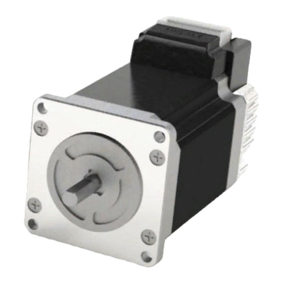
RODUCT NTRODUCTION BOUT The "CM3" is an integrated AC servo system with a built-in motor, encoder, driver and controller. The torque and speed have been increased while maintaining the ease of use of the conventional programming language “CML” (COOL MUSCLE Language). The CM3 provides the highest level of system solution simply by executing various operations such as PTP control and torque control from communication and I/O. -
Page 11: Cool Muscle Language (Cml
COOL MUSCLE L (CML) ANGUAGE COOL MUSCLE Language (CML) is a non-procedural ASCII command. By sending and receiving CML, you can easily change various settings, operate the motor directly, and check the status of the motor. CML is composed as follows. 2.2.1 Structure of CML Direct Command... -
Page 12: Control Type
ONTROL The following types exist in CM3. Each type can be switched from software. ⚫ The parameters differ for each type. After changing the type, always check the parameter settings again. Communication Direct Type control from PLC The point data set and stored in CM3 is executed by serial communication... -
Page 13: Model Number Configuration
ODEL UMBER ONFIGURATION CM3-17L50A Hardware Revision Max. Speed Motor Size Motor Length 17:42□ 50:5000RPM S:Short 23:56□ L:Long 2.4.1 CM3 Lineup Name Model Number CM3 42□ short CM3-17S50* CM3 42□ long CM3-17L50* CM3 56□ short CM3-23S50* CM3 56□ long CM3-23L50*... -
Page 14: Wiring Connection
IRING ONNECTION The wiring of CM3 is as follows. CM3 body part CM3 Body Connector CM3 Standard cable 400 mm * Please purchase cables separately CM3C1-400W I/O Cable1000 mm Communication Cable 1000 mm Power Cable 1000 mm CM3IO1-1000S CM3RS1-1000A CM3PW1-1000S +24Vdc Power Supply I/O Port... - Page 15 2.5.1 CM3 Body Connector The CM3 has a 24-pin connector on the top. The pin layout and names are as follows. Name Name ERROR OUT3/Z Phase RXD0 OUT2/B Phase TXD0 OUT1/A Phase STO_IN- STO_IN+ INPUT6- / PULSE B+ INPUT6- / PULSE B- INPUT5+ / PULSE A+ INPUT5- / PULSE A- IN_COM...
- Page 16 2.5.2 Power Cable Color Name Function +24Vdc POWER +24Vdc POWER Power Ground P-GND Power Ground P-GND STO input +(5~24Vdc) STO_IN+ (+5 – +24Vdc) STO input ―(Ground) STO_IN- (GND) Frame Ground CM3 Power cable1000 mm CM3PW1-1000S 2.5.2.1 STO Wiring Ex.1 Power Cable Wiring Ex.2 Power Cable...
- Page 17 2.5.3 I/O Cable Color Name Function IN_COM Input common Ground INPUT1 INPUT1 *OUT1 / A Phase *OUT1 / A Phase INPUT2 INPUT2 *OUT2 / B Phase *OUT2 / B Phase INPUT3 INPUT3 *OUT3 / Z Phase *OUT3 / Z Phase INPUT4 INPUT4 ERROR...
- Page 18 Wiring Ex.2 2.5.3.2 Input 5 and 6 Input 5 Input 6...
- Page 19 2.5.3.3 Pulse input wiring example 2.5.3.3.1 Wiring with Line driver output I/O Cable CCW / DIR / A-phase CW / STEP / B-phase 2.5.3.3.2 Wiring with open collector output I/O Cable CCW / DIR / A-phase CW / STEP / B-phase Open collector output is not adequate for long wiring.
- Page 20 2.5.3.4 Output 1 to 4 I/O Cable...
-
Page 21: Direct Type
IRECT VERVIEW Direct type CM3 can be controlled by communication. Up to 32-point data can be created, and each point data is composed of speed, acceleration, target position, etc. Operation starts when an execution command is sent by specifying a point data number. You can set all necessary elements for motion, such as target position, target speed, acceleration, deceleration, and torque. -
Page 22: Operation
PERATION With the direct type, point data such as position, speed, and acceleration can be set in CM3, and positioning can be performed according to each point data by serial communication. ⚫ The motor shaft rotates. Make sure that there is no problem even if the motor rotates. 3.2.1 PTP Motion This is a positioning operation that specifies the target position as a coordinate based on the origin. - Page 23 3.2.3 Direct Command Direct commands consist of point data definition commands and execution commands. Point data can be defined, and operation can be started with an execution command. 3.2.3.1 Point data definition command Name Command Range Unit Others PTP motion INC motion RUN mode 0~31...
- Page 24 3.2.3.2 Execution command The following execution commands are valid in direct type. Command Detail Pause the motion. Sending the command twice stops the program completely. Also used to clear warnings. Start origin search. Move to zero coordinate (Px.1=0). Set the current position to the origin (0) Start moving to the specified point.
-
Page 25: K Parameters
@K P ARAMETERS Each parameter can be set by communication. The format of the parameters are as follows. @K[No].1=[Value] 3.3.1 RUN Parameters Name Range Unit Restart Software limit function 0: Disable 1: Warn before moving 2: Warn after moving Sets the validity / invalidity of the software limit function and the timing when it becomes valid. The behavior when CM3 receives the execution command when the target position is set outside the software limit range is as follows. - Page 26 Name Range Unit Restart 0: One-way push without push failure judgement 1: One-way push with push failure judgement Push operation mode 2: Two-way push without push failure judgement 3: Two-way push with push failure judgement Push operation time 1~30000 msec Set the push operation mode and time.
- Page 27 Name Range Unit Restart MOVE signal output speed threshold 1~32767 100pulse/s Sets the threshold to output the MOVE signal. Temperature warning threshold 1~100 ℃ Sets the threshold for issuing a warning due to temperature rise. Load warning output threshold 10~100 Sets the threshold for issuing a warning when the load increases.
- Page 28 3.3.2 Origin Parameters Name Range Unit Restart Stopper detection Stopper detection (auto) Origin sensor Origin sensor (auto) Origin Signal Move to Z-phase after stopper detection ✓ Source Move to Z-phase after stopper detection (auto) Moves to Z phase after detecting origin sensor Move to Z-phase after origin sensor detection (auto) Move to Z phase Move to phase Z (auto)
- Page 29 3.3.3 GAIN Parameters Name Range Unit Restart Control Method 0: PPI control 1: Tuningless In PPI control, the position P gain, speed P gain, and speed I gain will be valid. For tuningless, the servo stiffness setting is enabled, and the gain will be automatically adjusted according to the load. Servo stiffness for tuningless 30~150 Specifies the servo stiffness for tuningless control.
- Page 30 3.3.4 Machine adjustment Parameters Name Range Unit Restart Stop Mode 0: Closed-loop mode 0.1 degree 1~36: Open-loop mode The open loop mode is a function to automatically switch from closed loop control to open loop control if there is no operation command for a fixed time after positioning is completed. In open loop mode, small vibrations due to hunting inherent to the servo motor can be suppressed.
- Page 31 3.3.5 Communication Parameters Name Range Unit Restart Baud rate 0: 38.4 kbps 1: 9.6 2: 19.2 3: 57.6 4: 115.2 Sets the communication baud rate with the host controller. Parity 0: None 1: Even 2: Odd Sets the parity for communication Delimiter 0: CR 1: CRLF...
- Page 32 3.3.6 I/O Parameters Name Range Unit Restart Input signal filter 1~10 msec ✓ Sets the noise filter processing time for the input signal from the host controller. The higher the number, the more the filter is applied and the slower the response to input. Signals shorter than the value set here are ignored.
- Page 33 3.3.7 Data Streaming Parameters Name Range Unit Restart 0: Disable CH0 data 1: Target position 2: Current position 3: Target speed CH1 data 4: Current speed 5: Target electric current 6: Current electric current 7: Load factor CH2 data 8: Voltage 9: Temperature 10: Input status CH3 data...
-
Page 34: I/O Function Assignment
FUNCTION SSIGNMENT CM3 has 6 digital inputs, 3 digital outputs, 1 error output, and 1 STO input. Various functions can be assigned by parameter setting. Each function is assigned to the rising edge, level, and falling edge of the input signal. Level Falling Rising... - Page 35 3.4.1.1.1 Teaching function with teaching mode The teaching function is a function that is valid only for the direct type and assumes point data specification using the teaching pendant. When the manual function assigned to input 4 is turned on, only the inching (jog) assigned to inputs 5 and 6 can be performed. Move the motor to an arbitrary position and specify that position as point data with the # command.
- Page 36 3.4.2 Digital Output Function Detail General-purpose ON / OFF by command In-position Output when in the in-position range WARN Output when warning status Individual ZONE (PZONE) Output when between point setting ZL and ZH ZONE Output when in a zone that can be set with parameters MOVE Output when speed exceeds MOVE output setting BUSY...
- Page 37 3.4.2.2 Push operation / Torque limit output Turns ON when the motor torque reaches the set value during push operation. The timing chart is as follows. Torque Push torque Time Push operation / Torque limit output BUSY Push operation END 3.4.2.3 ABZ Encoder Output When the output function is set to "ABZ encoder output", outputs 1 to 3 are assigned to the ABZ encoder output function.
-
Page 38: O Type
4 I/O T VERVIEW Point data can be set from a host control device such as a PC, and operations can be performed by input signals. Since the CM3 can store point data inside the motor, it is possible to control the motor using only I/O ports such as PLC and control PC without communication. -
Page 39: I/O Function Assignment
FUNCTION SSIGNMENT CM3 has 6 digital inputs, 3 digital outputs, 1 error output, and 1 STO input. Various functions can be assigned by parameter setting. Each function is assigned to the rising edge, level, and falling edge of the input signal. Level Falling Rising... - Page 40 Point Data # A0, S0, P0… A1, S1, P1… A2, S2, P2… A3, S3, P3… START A4, S4, P4… A5, S5, P5… A6, S6, P6… A7, S7, P7…...
- Page 41 4.2.2 Digital Output Function Detail General-purpose ON / OFF by command In-position Output when in the in-position range WARN Output when warning status Individual ZONE (PZONE) Output when between point setting ZL and ZH ZONE Output when in a zone that can be set with parameters MOVE Output when speed exceeds MOVE output setting BUSY...
- Page 42 4.2.2.2 Push operation / Torque limit output Turns ON when the motor torque reaches the set value during push operation. The timing chart is as follows. Torque Push torque Time Push operation / Torque limit output BUSY Push operation END 4.2.2.3 ABZ Encoder Output When the output function is set to "ABZ encoder output", outputs 1 to 3 are assigned to the ABZ encoder output function.
-
Page 43: Operation
PERATION With the I/O type, point data such as position, speed, and acceleration can be set in CM3, and positioning can be performed according to each point data by input signal. ⚫ The motor shaft rotates. Make sure that there is no problem even if the motor rotates. 4.3.1 PTP Motion This is a positioning operation that specifies the target position as a coordinate based on the origin. - Page 44 4.3.4 Direct Command Defines point data and saves data using an execution command. All motions are performed from the input point and cannot be executed with commands. 4.3.4.1 Point data definition command Name Command Range Unit Others Name PTP motion RUN mode INC motion RUN mode...
- Page 45 4.3.4.2 Execution command The following execution commands are valid in I/O type. Command Detail Save point data and @K parameters to the motor. Unless you send a save command, the changed data and parameters will not be saved on the motor. 1~3 General output on 1~3...
-
Page 46: K Parameters
@K P ARAMETERS Each parameter can be set by communication. The format of the parameters are as follows. @K[No].1=[Value] 4.4.1 RUN Parameters Name Range Unit Restart Software limit function 0: Disable 1: Warn before moving 2: Warn after moving Sets the validity / invalidity of the software limit function and the timing when it becomes valid. The behavior when CM3 receives the execution command when the target position is set outside the software limit range is as follows. - Page 47 Name Range Unit Restart 0: One-way push without push failure judgement 1: One-way push with push failure judgement Push operation mode 2: Two-way push without push failure judgement 3: Two-way push with push failure judgement Push operation time 1~30000 msec Set the push operation mode and time.
- Page 48 4.4.2 Origin Parameters @K Name Range Unit Restart Stopper detection Stopper detection (auto) Origin sensor Origin sensor (auto) Move to Z-phase after stopper detection Origin Signal Source ✓ Move to Z-phase after stopper detection (auto) Moves to Z phase after detecting origin sensor Move to Z-phase after origin sensor detection (auto) Move to Z phase Move to phase Z (auto)
- Page 49 4.4.3 GAIN Parameters @K Name Range Unit Restart Control Method 0: PPI control 1: Tuningless In PPI control, the position P gain, speed P gain, and speed I gain will be valid. For tuningless, the servo stiffness setting is enabled, and the gain will be automatically adjusted according to the load. Servo stiffness for tuningless 30~150 Specifies the servo stiffness for tuningless control.
- Page 50 4.4.4 Machine adjustment Parameters Name Range Unit Restart Stop Mode 0: Closed-loop mode 0.1degree 1~36: Open-loop mode The open loop mode is a function to automatically switch from closed loop control to open loop control if there is no operation command for a fixed time after positioning is completed. In open loop mode, small vibrations due to hunting inherent to the servo motor can be suppressed.
- Page 51 4.4.5 I/O Parameters Name Range Unit Restart Input signal filter 1~10 msec ✓ Sets the noise filter processing time for the input signal from the host controller. The higher the number, the more the filter is applied and the slower the response to input. Signals shorter than the value set here are ignored.
- Page 52 4.4.6 Streaming Data Parameters Name Range Unit Restart 0: Disable CH0 data 1: Target position 2: Current position 3: Target speed CH1 data 4: Current speed 5: Target electric current 6: Current electric current 7: Load factor CH2 data 8: Voltage 9: Temperature 10: Input status CH3 data...
-
Page 53: Pulse Type
ULSE VERVIEW The pulse type CM3 operates by receiving a pulse signal from a pulse oscillator such as a PLC. It is possible to replace the current pulse-controlled stepping motor or servo motor. The input format of the pulse signal can be switched by parameter and supports the following three methods. -
Page 54: I/O Function Assignment
FUNCTION SSIGNMENT CM3 has 6 digital inputs, 3 digital outputs, 1 error output, and 1 STO input. Various functions can be assigned by parameter setting. Each function is assigned to the rising edge, level, and falling edge of the input signal. Level Falling Rising... - Page 55 5.2.2 Digital Output Function Detail General-purpose ON / OFF by command In-position Output when in the in-position range WARN Output when warning status Individual ZONE (PZONE) Output when between point setting ZL and ZH ZONE Output when in a zone that can be set with parameters MOVE Output when speed exceeds MOVE output setting BUSY...
- Page 56 5.2.2.2 Push operation / Torque limit output Turns ON when the motor torque reaches the set value during push operation. The timing chart is as follows. Torque Push torque Time Push operation / Torque limit output BUSY Push operation END 5.2.2.3 ABZ Encoder Output When the output function is set to "ABZ encoder output", outputs 1 to 3 are assigned to the ABZ encoder output function.
-
Page 57: Operation
PERATION The pulse type CM3 operates by inputting a pulse signal. There are three ways to input pulses. 5.3.1 CW/CCW Pulse A Pulse B Pulse Count Direction 5.3.2 Direction/Pulse Pulse A Direction Pulse B Step Pulse Count Direction... - Page 58 5.3.3 A phase /B phase Pulse A Pulse B Pulse Count Direction 5.3.4 Direct Command 5.3.4.1 Execution Command Direct commands that can be used with the pulse type are as follows. Content Command Save point data and @K parameters to the motor. Unless you send a save command, the changed data and parameters will not be saved on the motor.
-
Page 59: K Parameters
@K P ARAMETERS Each parameter can be set by communication. The format of the parameters are as follows. @K[No].1=[Value] 5.4.1 RUN Parameters Name Range Unit Restart In-position Range 1~500 Pulse Specifies the range in which end-of-positioning is recognized. Torque Limit 10~100 Specifies the percentage of limiting torque when the torque limiting function is enabled by input 4. - Page 60 5.4.3 GAIN Parameters @K Name Range Unit Restart Control Method 0: PPI control 1: Tuningless In PPI control, the position P gain, speed P gain, and speed I gain will be valid. For tuningless, the servo stiffness setting is enabled, and the gain will be automatically adjusted according to the load. Servo stiffness for tuningless 30~150 Specifies the servo stiffness for tuningless control.
- Page 61 5.4.4 Machine adjustment Parameters Name Range Unit Restart Stop Mode 0: Closed-loop mode 0.1 degree 1~36: Open-loop mode The open loop mode is a function to automatically switch from closed loop control to open loop control if there is no operation command for a fixed time after positioning is completed. In open loop mode, small vibrations due to hunting inherent to the servo motor can be suppressed.
- Page 62 5.4.5 Pulse Parameters Name Range Unit Restart Pulse input mode 0: CW/CCW ✓ 1: Step/Dir 2: A / B-phase Sets pulse input mode to CW / CCW, Step / Dir, and A / B-phase. 5.4.6 I/O Parameters Input filter 1~10 msec ✓...
- Page 63 5.4.7 Data Streaming Parameters Name Range Unit Restart 0: Disable CH0 data 1: Target position 2: Current position 3: Target speed CH1 data 4: Current speed 5: Target electric current 6: Current electric current 7: Load factor CH2 data 8: Voltage 9: Temperature 10: Input status CH3 data...
-
Page 64: Common Settings
OMMON ETTINGS RIGIN EARCH PERATION Origin search can be selected from the following methods combining stopper detection, origin sensor, and Z phase. Value Name Stopper detection Stopper detection (auto) *Origin sensor *Origin sensor (auto) Move to Z-phase after stopper detection Move to Z-phase after stopper detection (auto) *Moves to Z phase after detecting origin sensor *Move to Z-phase after origin sensor detection (auto) - Page 65 After detecting the wall, it starts moving to the origin position + offset position. The origin position at the time of pushing origin return is 50 points per rotation as shown in the figure below. Wall Origin Origin Wall 6.1.1.1 Origin search in the CW direction The origin point (origin point 3) of the current origin point-1 (origin point 4 for wall detection in the above figure) is the origin position.
- Page 66 6.1.2 Origin Sensor Origin sensor input can be set only for INPUT1 of I/O type and direct type. If a origin search operation is performed when the function of INPUT1 is not set to the home sensor or hardware limit, an operation error will be issued. The origin search operation by the origin sensor is always detected at the rising edge of the active sensor set in the origin return direction.
- Page 67 6.1.2.3 Origin search using both hardware limit and origin sensor The sequence when the origin sensor is set to input 1 and the hardware limit CW is set to input 2 is shown below. Origin- sensor Hardware- limit ① ② STOP ④...
-
Page 68: Query Command
UERY OMMAND By sending a query command to the motor, you can check the data set for the motor and the current status. 6.2.1 Point Data / Parameters Query Detail Comment ?0~31 Specified point setting data ?0~?7 for I/O type List of operation types List of position data List of speed data... - Page 69 6.2.4 I/O Status Convert binary to decimal in order from output 4 to 1 with Output information 0 off and 1 on. OUT1.1=0:OFF 1:ON OUTPUT1 OUTPUT2 OUT2.1=0:OFF 1:ON OUT3.1=0:OFF 1:ON OUTPUT3 Error output OUT4.1=0:OFF 1:ON Convert binary to decimal in order from input 6 to 1 with Input information 0 off and 1 on.
- Page 70 6.2.6 Warning Information (?199) The warning information can be checked by the query command. “?199”. Even if a warning occurs, the motor will not be turned off. It can be used for preventive maintenance by using temperature and load warnings. Format:...
-
Page 71: Status Led
TATUS The current motor status is indicated by 7 color (blue, green, red, magenta, cyan, yellow, white) LED displays. The table below shows the status and LED display. Mage Flashing Status Green Cyan Blue White Yellow Pattern Alternate ✓ ✓ ✓... -
Page 72: Specification
PECIFICATION ASIC SPECIFICATIONS 7.1.1 CM3-17S/L Items CM3-17S50* CM3-17L50* Input Voltage +24Vdc Input / Peak current 4 [A] / 5 [A] Motor Wattage 60 [W] 60 [W] Max. Speed 5000 [min Rated Torque 0.25 [N・m] 0.42 [N・m] Max. Torque 0.32 [N・m] 0.65 [N・m] Rotor Moment of Inertia 0.036 ×... - Page 73 7.1.2 CM3-23S/L Items CM3-23S50* CM3-23L50* Input Voltage +24Vdc Input / Peak current 5[A] / 5[A] 5[A] / 5[A] Motor Wattage 80 [W] 100 [W] Max. Speed 5000 [min Rated Torque 0.36 [N・m] 1.2 [N・m] Max. Torque 0.45 [N・m] 1.50 [N・m] Rotor Moment of Inertia 0.1×10 [kg・m...
-
Page 74: Speed/Power/Torque Specification
PEED OWER ORQUE PECIFICATION 7.2.1 CM3-17S CM3-17S 0.35 Torque 0.30 0.25 0.20 0.15 0.10 Power 0.05 0.00 1000 1500 2000 2500 3000 3500 4000 4500 5000 Speed [min-1] 7.2.2 CM3-17L CM3-17L 0.700 Torque 0.600 0.500 0.400 0.300 0.200 Power 0.100 0.000 1000 1500... - Page 75 7.2.3 CM3-23S CM3-23S 0.500 Torque 0.450 0.400 0.350 0.300 0.250 0.200 Power 0.150 0.100 0.050 0.000 1000 1500 2000 2500 3000 3500 4000 4500 5000 Speed [min 7.2.4 CM3-23L CM3-23L 1.600 Torque 1.400 1.200 1.000 0.800 0.600 Power 0.400 0.200 0.000 1000 1500...
-
Page 76: Electric Specification
LECTRIC PECIFICATION Items Value 4.8~26 [V] Input Voltage Digital Input 0.8 [V] High 4.2 [V] Input pulse range 500 [kHz] Pulse Input Duty 50 +/-10% Max. voltage 50 [V] Digital Output Max. continuous current 20mA 9.6~115.2 [kbps] Communication Line baud rate (38.4 [kbps] fixed for I/O and pulse type) -
Page 77: Dimensions
IMENSIONS 7.4.1 CM3-17S 7.4.2 CM3-17L... - Page 78 7.4.3 CM3-23S 7.4.4 CM3-23L...
-
Page 79: Others
THERS EVISION ISTORY Date Revision Number Page Object Revised Items Feb. 2020 MDUG-CM3/20203E-01 New Draft...
Need help?
Do you have a question about the Cool Muscle 3 and is the answer not in the manual?
Questions and answers