
Related Manuals for EVSE Viridian EV EPC20 Series

Summary of Contents for EVSE Viridian EV EPC20 Series
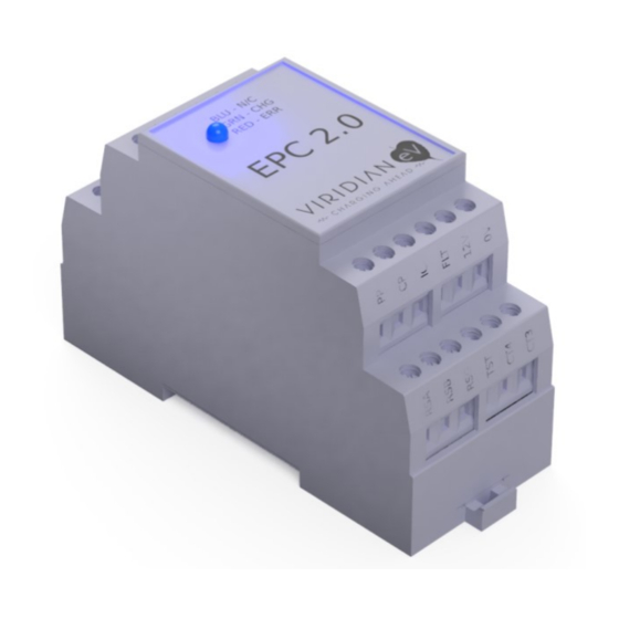
- Page 1 Issue 1.2 May 2020 EVSE Protocol Controller 2.0 (EPC 2.0) | Viridian EV EVSE Protocol Controller 2.0 (EPC 2.0) http://viridianev.co.uk info@viridianev.co.uk...
-
Page 2: About This Documentation
Issue 1.2 May 2020 EVSE Protocol Controller 2.0 (EPC 2.0) | Viridian EV Introduction 1.1 ABOUT THIS DOCUMENTATION PURPOSE OF THIS DOCUMENTATION This Manual contains all the information you need for commissioning and using the Viridian EV EPC 2.0. They are intended for use by electrically skilled persons who commission the device. -
Page 3: Safety Instructions
CAUTION: PLEASE OBSERVE THE SAFETY INSTRUCTIONS AND LEGAL NOTES Installation requirements for electrical equipment and EVSE vary by country and jurisdiction. It is the responsibility of the installer/user of this product to ensure that legal installation requirements are met. In the UK, this product must be installed and used by a competent and qualified person who will ensure the equipment adheres to the IEE wiring regulations BS7671 (18th Edition or later) and current Building regulations. - Page 4 Issue 1.2 May 2020 EVSE Protocol Controller 2.0 (EPC 2.0) | Viridian EV DESCRIPTION 3.1 OVERVIEW OF THE EPC 2.0 The EPC 2.0 is a DIN rail mounted control module for IEC 61851 compatible EV charge points. Key features include RCM support and PEN Loss detection, helping charge point manufacturers and installers meet regulations in a cost-effective way and protect against electric shock in the unlikely event of an earth and neutral fault problem.
- Page 5 Issue 1.2 May 2020 EVSE Protocol Controller 2.0 (EPC 2.0) | Viridian EV 3.2 EPC 2.0 FEATURES DEVICE VERSIONS • The Viridian EV EPC 2.0 has part numbers in this format: EPC20(1)(2)(3). i.e. EPC20 P10-R • (1) indicates the model B = Basic P = Plus •...
- Page 6 It is up to the user creating the EVSE using an EPC 2.0 to understand if it is a single phase or three phase installation and apply the requirements of BS 7671: 2018 amendment 1 accordingly.
- Page 7 Important note: RCM not installed If no RCM device is being used in the EVSE then this functionality needs to be disabled as per the configuration table in this document, reference section ( 4.1. ) 3.5 SELECTABLE CHARGING CURRENT ( IC ) Selecting charging current on installation The EPC 2.0 can be configured to restrict the maximum current available to charge the EV on installation of the device .
- Page 8 3.6 FUNCTION APPLICATION EXAMPLE The following shows a schematic application example of an electric vehicle charge point / EVSE assembled with a EPC 2.0. For example, application option A shows a Type A RCD, an MCB and the 16A / 32A contactor. Application example B shows a RCBO (Type A, C curve) and a 16A / 32A contactor.
-
Page 9: Ventilation Requirement
The EPC 2.0 is designed to operate with available charging current signals of 16A and 32 A ,depending on the current carrying capacity of the cable that is detected. Note : The advertised current from the EVSE maybe downgraded depending on the current carrying capacity of the cable detected. -
Page 10: Dip Switch
Issue 1.2 May 2020 EVSE Protocol Controller 2.0 (EPC 2.0) | Viridian EV Configuration 4.1 DIP SWITCH Configurable features are selected on a 10-way DIP switch located on the top of the EPC 2.0 .The device will be provided with the default configuration of the DIP switch ( see table ) . The Unit will be supplied with the push fit lid to fit after the correct selection for 16A or 32A installation. - Page 11 Issue 1.2 May 2020 EVSE Protocol Controller 2.0 (EPC 2.0) | Viridian EV 4.2 INPUT CURRENT TO VEHICLE INPUT CURRENT RESISTANCE SELECTION INFORMATION An Input Current (IC) resistance (or equivalent voltage) restricts the current maximum advertised by the EPC 2.0 and therefore the operating current while charging .
- Page 12 Issue 1.2 May 2020 EVSE Protocol Controller 2.0 (EPC 2.0) | Viridian EV Max Current IC Resistance (Ohms) IC Equivalent Voltage (V) 1.5588 1.5084 1.4589 1.4080 1.3610 1.2908 1.2462 1.2006 1.1568 1.0938 1.0537 0.9968 0.9580 0.9050 0.8506 0.8018 If an IC resistor is not fitted the EPC 2.0 will default to the maximum current proclaimed as available determined by the DIP switch of either 16A or 32A If an IC resistor or less than 100-Ω, MIN, is fitted then the EPC 2.0 will reduce the advertised current capacity...
-
Page 13: Led Display & Troubleshooting
EVSE Fault detected. Charging deactivated (Status F) See Troubleshooting guide. GENERAL TROUBLESHOOTING To test if the EVSE built with the EPC is functioning as intended it is suggested to initiate a charging session and check the operation of the unit by following the sequence below: •... -
Page 14: General Troubleshooting
Protective Earth in order for the system to operate correctly. • Ensure all connections in the EVSE are tightened to the correct Torque setting. For M3 terminals on the EPC: 0.6-1.2Nm - (factory setting of 1nm). Consult relevant manufacturer documentation for oth- er parts used •... -
Page 15: Connecting Terminals & Terminal Assignment
6.1 CONNECTING TERMINALS & TERMINAL ASSIGNMENT TETHERED CABLE “Tethered” means that the charging cable is permanently connected to the EVSE.. The RCBO should be rated at the maxi- mum current ( 16A/ 32A ) set via the DIP switch ( See Configuration ) FREE CABLE / SOCKET VERSION “Free”... -
Page 16: All Versions
6.2 EPC TERMINAL ASSIGNMENT ALL VERSIONS COMMISSIONING To test if the EVSE built with the EPC is functioning as intended it is suggested to initiate a charging session and check the operation of the unit by following the sequence below: •... - Page 17 If lock feedback has been selected via DIP switch 4 Relay 1 & 2 (common) Live from integrated electrical protection or mains terminals Relay 1 to coil on the EVSE ( 16A / 32A ) Contactor Relay 2 to coil on the Auxiliary Contactor...
-
Page 18: 230 V Ac Power Supply
Issue 1.2 May 2020 EVSE Protocol Controller 2.0 (EPC 2.0) | Viridian EV 6.3 230 V AC POWER SUPPLY WIRING EXAMPLE: Socket Outlet Optional fitting : Refer to section 4.2 WARNING: THE EXTERNAL CONTACT BLOCKS USED MUST BE FLOATING AND SAFELY SEPARATED FROM UNSAFE CIRCUITS. -
Page 19: External Led Connector
VEHICLE INTERFACE ACCORDING TO IEC 61851 Connect the terminals “CP” and “PP” (on free cable versions only) directly to the EVSE socket First connect the ground connection of the vehicle interface to the 0V reference point and then route this potential from there DANGER: NEVER USE THE TERMINALS OF THE VIRIDIAN EPC 2.0 CHARGING... -
Page 20: Mounting Onto Standard Rail
Issue 1.2 May 2020 EVSE Protocol Controller 2.0 (EPC 2.0) | Viridian EV MOUNTING 7.1 MOUNTING ONTO STANDARD RAIL Clip the device (a) vertically onto the horizontal DIN rail (b). Swing the device downward until the unlocking slider on the DIN rail clicks into place. -
Page 21: Service And Maintenance
Issue 1.2 May 2020 EVSE Protocol Controller 2.0 (EPC 2.0) | Viridian EV SERVICE & MAINTENANCE 8.1 REPLACING THE DEVICE MAINTENANCE The Viridian EPC 2.0 charging controller is maintenance-free. WARNING: THERE ARE NO USER-REPLACEABLE FUSES WITHIN THE EPC VIRIDIAN EPC 2.0 REPLACEMENT REQUIREMENT: Ensure that the plant and the device itself are de-energized. -
Page 22: Dimensional Drawings
Issue 1.2 May 2020 EVSE Protocol Controller 2.0 (EPC 2.0) | Viridian EV DIMENSIONAL DRAWINGS...
Need help?
Do you have a question about the Viridian EV EPC20 Series and is the answer not in the manual?
Questions and answers