Table of Contents
Advertisement
Quick Links
Advertisement
Table of Contents

Related Manuals for KERAFLO Tanktronic


Summary of Contents for KERAFLO Tanktronic
- Page 1 Tanktronic Installation Guide...
- Page 2 Notes ................................................................................................................................................................................................................................................................................................................................................................................................................................................................................................................................................................................................................................................................................................................................................................................................................................................................................................................................................keraflo.co.uk...
-
Page 3: Table Of Contents
Introduction ....................4 Quick Start ....................5 Levels ....................8 Valves ....................10 - Tanktronic Servo Ceramic Valve (SCV) ............. 10 - Tanktronic Control Valve ............. 13 - Generic Non-Latching Valve ............. 14 - Commisioning Valves ............. 14 Manual Config .................... -
Page 4: Introduction
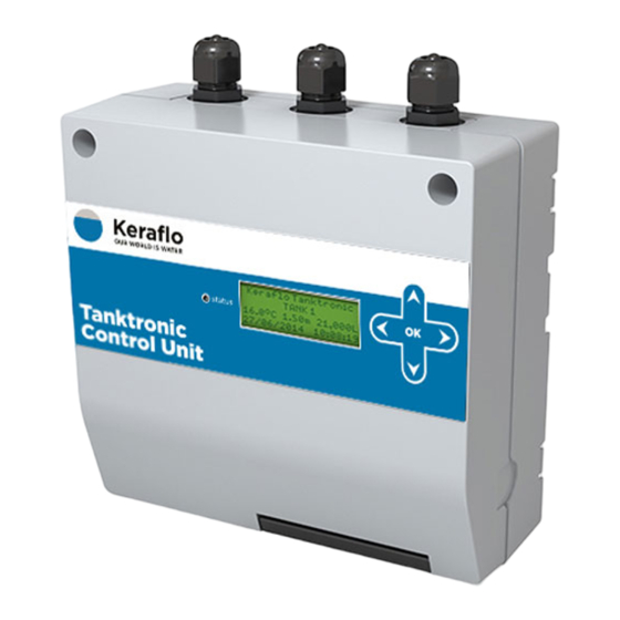
Control Unit (TT/41, TT/42, TT/43 and TT/44) The primary monitoring and control hardware for the Tanktronic system. The unit can manage up to 4 x individual tank sensors, 8 x Tanktronic Servo Ceramic Valves, and 2 x Tanktronic Control Valves plus additional third party devices. -
Page 5: Quick Start
Installing the Control Unit: Ensure cables are fed through the cable Use drilling glands. template and wall fixings Use tabs provided. to align modules side by side A DIN rail Snap out can also to connect be used S-Module & Battery Module keraflo.co.uk... - Page 6 Tanktronic Control Module here Valve here Tanktronic requires a 230v/50Hz single phase supply from a switched fused 3A supply. Connect with a suitable spec power cable. First slide the cable through the safety sleeve, then attach it to the socket.
- Page 7 For more advanced set up complete the wizard and use Main Menu > System > Config (see Page 15). Setting Date and Time: To set the date and time (which is not included in the Setup Wizard) use: Main Menu > System > Config > Set Clock keraflo.co.uk...
-
Page 8: Levels
Prior to commissioning Tanktronic, it is recommended to list the settings you require by using the Settings Log checklist on Page 24. Monitoring Only: When using Tanktronic for monitoring purposes only, the Fill Delay and Open Level is used for setting Alarm Levels. keraflo.co.uk... - Page 9 Three types of filling valves are supported. All valves operate from the tank’s specified Close Level and Fill Delay settings, as illustrated on Page 8. • Tanktronic Servo Ceramic Valve (SCV) - See Page 10 • Tanktronic Control Valve - See Page 13 •...
-
Page 10: Valves
Bung SCV with cable Note: Tanktronic Control Unit and sensors are sold separately from SCV. Maximum of 8 SCVs per system. Control Unit software version must be Issue 2 or later to work with SCV. The software issue can be checked through the menu: Main Menu > System > Status >... - Page 11 Note: Only use the Connection Box provided to connect the SCV to the Control Unit. Do not tamper with or modify the Connection Box in any way, when fitting the cable to the Control Unit. keraflo.co.uk...
- Page 12 “Cleaning” fault. Auto Retry: Tanktronic can detect if the valve cannot complete a cycle due to debris. The SCV will automatically release the valve by retrying the Open/Close action. If cycle cannot be completed, then an alarm is sent as a “Valve Jammed”...
-
Page 13: Tanktronic Control Valve
Valves Tanktronic Control Valve A range of metal-bodied Tanktronic Control Valves is available, in 2”, 21/2“, 3”, 4” and 6” sizes. These valves should be specified when high flow rates are required. Included: Control Valve with solenoid, Discharge Pipe Flanged Assembly, Stub Flange and Backing Ring. -
Page 14: Generic Non-Latching Valve
A non-latching 3rd party inlet valve may be controlled from the Tanktronic. The live feed to the valve should be connected through the Volt-Free Contact Outputs on the Tanktronic Control Unit, as illustrated in the drawing on Page 9 (for VFCO spec please see Back Page). -
Page 15: Manual Config
Overide Level. (See Devices Page 17) Tank Shape: Tanktronic assumes your tank is a uniform shape and the water volume is a function of the cross sectional area x water depth. If your tank is a Horizontal Cyclinder and the area changes with depth, then you must change the default shape: Main Menu >... - Page 16 Manual Config Alarms: Tanktronic will raise an alarm in the following circumstances, which will cause the LED to flash red and an alarm log created: • Alarm level High or Alarm Level Low is exceeded • Alarm Temp High or alarm Temp Low is exceeded •...
-
Page 17: Devices
• Active/Inactive state • Address Connecting to Building Management Systems (BMS): Tanktronic can be connected to proprietary BMS systems via the VFC available on the Control Unit or S-Module. Reset Latched Devices: If manual reset is selected the device will require manual intervention to reset the VFC. - Page 18 Normal inlet valve, as in default config. Opens when level drops to the fill delay level threshold, and closes when level reaches close Tanktronic SCV level threshold, or sensor not responding. (For balanced tank shared inlet valves, both tanks are controlled together) Normal inlet valve, as in default config.
- Page 19 (close high, open low), fail-safe state (high), Tank alarm (no) Shared (separate), alarmed (disabled), auto/ manual reset (man), fail-safe state (active), Tank or System Tank or System VFCI polarity (normally closed) Tank or System VFCO Polarity (normally closed) Tank or System keraflo.co.uk...
-
Page 20: Modules
An S-Module can be added to provide 2 more VFCOs, 2 more VFCIs and 2 more SOLs, if required, in addition Select button, to the Tanktronic Control Unit’s maximum of 2 VFCOs, press when instructed 2 VFCIs and 2 SOLs. -
Page 21: Holiday Mode
Mode Holiday Mode Tanktronic allows the user to set a schedule of operation of the tanks at alternative levels – typically during ‘holiday’ periods of reduced activity. Holiday Levels are set in the tank menu and are specific to individual tanks. Each tank can be set with its own holiday level for: •... -
Page 22: Sensor
If additional tanks have been added, the system must be configured so it recognises the sensor of each tank. Main Menu > Tank X > Config > Devices > Add device > KERAFLO SENSOR Name the sensor and select the next free input address. -
Page 23: Menus
Menus Status Menu: The status of Tanktronic sensors, valves and devices can be reviewed via the “Status” menu option. This is useful for fault finding and checking the state of valves in multiple tanks. You can view water level and temperature, devices (for example, is a valve open or closed), software version and more. -
Page 24: Settings
Menus Settings log: Prior to commissioning Tanktronic, it is recommended to list the settings you require using this quick reference checklist: Tank 1 Tank 2 Default Enter Required Setting Enter Required Setting Area (10.0m) ....................Close Level (1.2m) .......... -
Page 25: Dimensions
Dimensions Dimensions S-Module/ Control Unit/Repeater Unit Battery Module 194mm 204mm 85mm 144mm Tanktronic Servo Ceramic Valve (SCV) available from 3/4” fittings to 2” fittings: Servo Ceramic Valve (SCV) 3/4” SCV20 19.5 34.5 SCV25 26.9 34.5 1” SCV32 35.4 11/4” SCV40 11/2”... -
Page 26: Menu Map
Close Devices Temp Level Water Fill Delay Level Alarm Water Level H Volume Override Devices Level H Alarm Level L Override Level L Alarm Temp H Override Temp High Alarm Temp Low Override Temp Low Tank Shape Holiday Levels keraflo.co.uk... - Page 27 Clock Override Setup Tank Devices Listed Devices Wizard Layout Tank By Address Devices Edit Device Layout Secondary Devices by Delete Device Tanks Address Advanced Devices Select Device S-Modules Deselect Device Calibrate Device Config Menu Timeout Holiday Times System Reboot keraflo.co.uk...
-
Page 28: Specifications
Control Unit to Sensor Connection Box: 2 core 1mm², 100m max length Control Unit to SCV Connection Box: 2 core 2.5mm², 15m max length Control Unit to Tanktronic Control Valve: 2 core 1mm², 50m max length Volt Free Contact Outputs (VFCO): Number: 2 per Control Unit &...
Need help?
Do you have a question about the Tanktronic and is the answer not in the manual?
Questions and answers