Table of Contents
Advertisement
Advertisement
Table of Contents
Troubleshooting

Related Manuals for VRmagic Eyesi

Summary of Contents for VRmagic Eyesi
- Page 1 Eyesi Surgical Simulator Installation and Operating Guide Platform 2.11...
- Page 2 +49 621 400 416 0 +49 621 400 416 99 info@vrmagic.com www.vrmagic.com In case of a service request please visit service.vrmagic.com or send an e-mail to service@vrmagic.com. Eyesi Surgical Simulator – Installation and Operating Guide Original instructions Document version: 3.7 Date of issue: March 20, 2020 Applicable to: Eyesi Surgical Simulator platform 2.11...
-
Page 3: Table Of Contents
Installing the Stereo Microscope ..............26 Attaching the Microscope Eyepieces ............27 Installing the Optional BIOM ................. 28 4.10 Checking the Voltage Settings (applies only to lifting columns of type TES2) ..........30 Eyesi Surgical Simulator – Installation and Operating Guide... - Page 4 6.1.5 Touch Screen ....................51 6.1.6 Monitor Arm ....................51 6.1.7 Power Connection ...................52 6.1.8 Simulator PC ....................53 6.1.9 Operating Table ....................53 6.1.10 Lifting Column and Support Feet ..............53 Storage ......................54 Transport ....................... 54 Eyesi Surgical Simulator – Installation and Operating Guide...
- Page 5 Troubleshooting ..................... 62 Service and Support ..................64 Repairs ......................65 Technical Data .................. 66 Appendix – Packing Guide .............. 67 10.1 Cardboard Boxes ................... 67 10.2 Plastic Transport Containers ................73 Eyesi Surgical Simulator – Installation and Operating Guide...
-
Page 6: General Information
General Information 1 General Information This guide describes the assembly, disassembly, and basic operation of the Eyesi Surgical Simulator, as far as relevant for the safe and error-free operation of the product. This guide does not describe the simulator software or any issues related to the software. -
Page 7: Transfer Of Ownership
Always keep this operating guide in the vicinity of the simulator. When the simulator is transferred to another party, make sure that this operat- ing guide is transferred with it. Never transfer single components or parts of the simulator. Eyesi Surgical Simulator – Installation and Operating Guide... -
Page 8: Safety
2 Safety 2.1 Intended Use and Improper Use The Eyesi Surgical Simulator is a virtual reality training simulator for eye surgery. Eyesi Surgical can be used to train vitreoretinal and cataract surgery. Eyesi Surgical is designed to train techniques, procedures and manual capabilities in preparation for surgery on the human eye. -
Page 9: General Product Safety
• Do not place the simulator PC on a carpet or rug with long fibers. • Do not place the simulator PC in a narrow or cramped space. • Do not cover the simulator PC during operation. Eyesi Surgical Simulator – Installation and Operating Guide... -
Page 10: Assembly And Connection To A Power Supply
Trying to change the voltage setting while the simulator is connected to a power source, may lead to injury or death through electrical shock. Always disconnect the simulator from the power source before changing the voltage setting. Eyesi Surgical Simulator – Installation and Operating Guide... -
Page 11: Operation
Otherwise electric shock hazard or device damage may occur. Remove the power plug immediately if liquid enters any part of the enclosure. In this case, the equipment needs to be checked by VRmagic or an authorized service technician. -
Page 12: Disassembly, Transport, And Storage
Trying to fully unscrew the four screws un- derneath the mounting receptacle will damage the receptacle. Only slightly loosen the screws (approx. one full revolution). This should be sufficient to pull out the monitor arm. Eyesi Surgical Simulator – Installation and Operating Guide... -
Page 13: Care, Maintenance, And Disposal
If you attempt to change the fuses while the simulator is connected to power, there is the risk of death or serious injury through electrical shock. Always disconnect the simulator from power before changing the fuses. Eyesi Surgical Simulator – Installation and Operating Guide... - Page 14 Using the wrong type of fuse may cause damage through high currents. Only use slow-acting micro-fuses of the type T 6.3 A L 250 V as replacement. Do not use replacements or spare parts not approved by VRmagic. The use of in- compatible components may involve considerable danger for the user and may damage your system.
-
Page 15: Unpacking And Product Overview
The shipping boxes should be carried by two people only. Unpacking If you identify any damage or missing parts, please contact VRmagic immediately. On receipt of the goods, check the following: • Check the packaging for damage. Completely unpack the shipping boxes and their contents. -
Page 16: Scope Of Delivery
1 set of vitreoretinal handpieces provided in an instrument box consisting of: 1 light source, 1 straight handpiece, 1 forceps 1 Oculus BIOM /SDI including 2 screws, 2 washers, and spare round belts (optional) ® ® Eyesi Surgical Simulator – Installation and Operating Guide... -
Page 17: Simulator Components
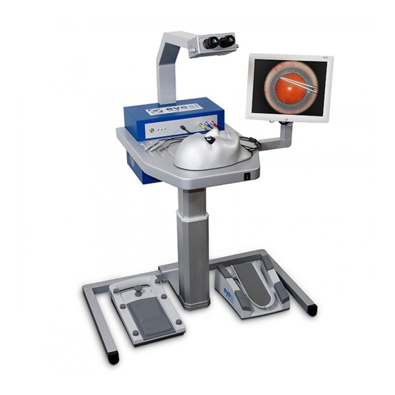
Unpacking and Product Overview 3.3 Simulator Components Fig. 1: Overview of the Eyesi Surgical simulator Stereo microscope Touch screen Surgical interface head Optional wrist rest Height adjustable operating table Instrument foot pedal Microscope foot pedal Lifting column Simulator PC 10 Instruments... -
Page 18: Installation
(e.g. tripping) cannot occur. • If multiple devices are used in the same space, ensure that the temperature and humidity constraints of all devices conform to the requirements. Eyesi Surgical Simulator – Installation and Operating Guide... -
Page 19: Assembling The Support Feet And Lifting Column
Place the operating table’s mounting plate on top of the matching plate on the lifting column. Make sure the M6 x 25mm screws are placed in front of the two slots in the lifting columns mounting plate. Eyesi Surgical Simulator – Installation and Operating Guide... - Page 20 There is a connection cable with a round plug located at the top of the lifting column. The cable is used for height adjustment of the operating table. Connect the cable with the round plug to the matching jack located underneath the operating table. Eyesi Surgical Simulator – Installation and Operating Guide...
-
Page 21: Installing The Simulator Pc
Audio jack for touch screen DisplayPort connector for microscope HDMI port for additional monitor/projector 10 USB ports for foot pedals and additional peripheral devices 11 RJ45 port 12 VRx connector for microscope Eyesi Surgical Simulator – Installation and Operating Guide... - Page 22 To ensure the simulator PC is securely mounted, verify that the two safety pins at the end of the operating tables’s arms are snapped up securing the simula- tor PC in the operating table. Fig. 8: Check that the safety pins are snapped up Eyesi Surgical Simulator – Installation and Operating Guide...
-
Page 23: Attaching The Monitor Arm
Introduce the monitor arm into the mounting receptacle. Push the monitor arm into the receptacle as far as it will go. Tighten the four screws under the receptacle using the 5 mm hexagon key. Fig. 10: Tightening the screws Eyesi Surgical Simulator – Installation and Operating Guide... -
Page 24: Attaching And Connecting The Touch Screen
Make sure that the monitor arm has been securely mounted to the mounting receptacle before attaching the touch screen (Â section 4.5 on page 23). Eyesi Surgical Simulator – Installation and Operating Guide... - Page 25 DVI port of the touch screen and plug it in. Tighten both screws on the plug by hand to ensure it is firmly connected. Plug the power cable into the power inlet of the touch screen. Eyesi Surgical Simulator – Installation and Operating Guide...
-
Page 26: Installing The Stereo Microscope
(Â Fig. 14 on page 26, #1). Tighten it using the 5 mm hexagon key. Fig. 14: Inserting the screw and connecting DisplayPort and VRx plug Eyesi Surgical Simulator – Installation and Operating Guide... -
Page 27: Attaching The Microscope Eyepieces
Malfunction due to mixed up hardware The optics within the eyepieces and the microscope socket are calibrated and cannot be used with the hardware of another Eyesi Surgical simulator. Attaching the microscope eyepieces: Remove the sealing caps from the eyepieces and microscope socket. -
Page 28: Installing The Optional Biom
Installing the optional BIOM: Position the BIOM underneath the mounting bracket of the microscope arm and align the holes of the BIOM with the two slits in the mounting bracket (Â Fig. 17 on page 29). Eyesi Surgical Simulator – Installation and Operating Guide... - Page 29 Plug the other end of the USB cable coming out of the back of the micro- scope arm into an USB port on the back side of the simulator PC (Â Fig. 6 on page 21). Eyesi Surgical Simulator – Installation and Operating Guide...
-
Page 30: Checking The Voltage Settings (Applies Only To Lifting Columns Of Type Tes2)
Check the voltage displayed on the voltage selector switch. ▷ The displayed voltage has to match the power supply voltage in your country. ▷ If a wrong voltage is preset, adjust the voltage setting according to the fol- lowing instructions. Eyesi Surgical Simulator – Installation and Operating Guide... -
Page 31: Adjusting The Voltage Settings (Applies Only To Lifting Columns Of Type Tes2)
Now take the voltage selector out of the voltage selector switch (3). ▷ There are four different voltages displayed on the voltage selector (100 V AC, 120 V AC, 230 V AC, 240 V AC). Eyesi Surgical Simulator – Installation and Operating Guide... -
Page 32: Placing The Simulator In Its Final Location
If not already the case, place the simulator in its final location. Make sure the connections on the backside of the simulator PC remain easily accessible. If necessary, adjust the 4 leveling feet under the support feet until the unit is leveled and does not wobble. Eyesi Surgical Simulator – Installation and Operating Guide... -
Page 33: Connecting To Power
(Â section 4.10 on page 30). Eyesi is supplied with power through a single socket connection at the bottom of the lifting column. Power is lead through the column. At the top end of the column a power cable leads to the power inlet of the simulator PC (Â Fig. -
Page 34: Connecting The Surgical Interface Head
(e.g. from rolling the chair). 4.15 Connecting the Surgical Interface Head Cataract and vitreoretinal interface heads Two surgical interface heads are available for training on Eyesi Surgical. Fig. 22: Surgical interface heads Vitreoretinal head Cataract head Connecting the surgical interface head: Put the surgery interface head on the operating table. -
Page 35: Connecting And Disconnecting The Handpieces
Mixing the cataract and vitreoretinal handpieces leads to malfunction. Only use cataract or vitreoretinal handpieces at a time. Only use handpieces with the corresponding surgical interface head. Info Handpieces interchangeable anytime The surgical handpieces can be interchanged while the simulator running. Eyesi Surgical Simulator – Installation and Operating Guide... - Page 36 Fig. 26: Connecting the handpieces Push the handpiece plugs into the ports. Always store the set of handpieces that is not in use in the provided storage box to prevent damage or injury. Eyesi Surgical Simulator – Installation and Operating Guide...
-
Page 37: Connecting An Additional Monitor Or Projector
To connect an additional monitor or video projector to the simulator, use the HDMI port of the simulator PC (Â Fig. 6 on page 21). The HDMI port outputs the image which is seen through the microscope. Eyesi Surgical Simulator – Installation and Operating Guide... -
Page 38: Operation
Switching the simulator on: To start the surgical simulator, press the power button (1). Wait for the green LED (2) to go on. ▷ After some time, the login screen appears on the touch screen. Eyesi Surgical Simulator – Installation and Operating Guide... -
Page 39: Switching The Simulator Off
(less than 0.5 seconds). Switching the simulator off: Tap the shutdown button on the login screen. Fig. 31: Shutdown button on the login screen ▷ A drop-down list is displayed. Eyesi Surgical Simulator – Installation and Operating Guide... - Page 40 Do not disconnect the simulator from the power supply before all LEDs are off! Normally, it is not necessary at all to disconnect the power supply. Fig. 33: Do not disconnect until shut down is complete Eyesi Surgical Simulator – Installation and Operating Guide...
-
Page 41: Adjusting The Height Of The Operating Table
Keep a safety distance of the simulator to neighboring objects of minimum 15 cm (6”). Adjusting the operating table: Press the button at the front edge of the table to move the table up or down. Fig. 34: Adjusting the table height Eyesi Surgical Simulator – Installation and Operating Guide... -
Page 42: Adjusting The Stereo Microscope
For an optimal ergonomic position, adjust the inclination of the microscope. Fig. 36: Stereo microscope Microscope housing: Tilt up/down to adjust inclination Eyepieces: Turn clockwise/counterclockwise to adjust diopter settings Eyepieces: Tilt left/right to adjust pupil distance Eyesi Surgical Simulator – Installation and Operating Guide... -
Page 43: Activating The Biom For Vitreoretinal Training
The BIOM provides good vision in the periphery as well as high magnification of the macula area. Eyesi Surgical can be equipped with an Oculus BIOM/SDI hardware mimic, which is operated like a real BIOM. The BIOM is mounted to the stereo microscope of Eyesi Surgical. - Page 44 Fig. 37: Activating the BIOM Activate the SDI by turning the SDI switch clockwise (Â Fig. 38 on page 44, #2) until the yellow SDI LED lights up (#1). Fig. 38: Activating the SDI Eyesi Surgical Simulator – Installation and Operating Guide...
-
Page 45: Deactivating The Biom For Cataract Training
The touch screen settings are set to factory defaults before shipping. Apart from the sound volume, the monitor settings do not need to be adjusted. Al- teration of the default settings may lead to reduced image quality. Eyesi Surgical Simulator – Installation and Operating Guide... - Page 46 Press or to select the desired menu item. Press SELECT to enter the selected menu item. Use or and SELECT to enter submenus and change settings. Press MENU several times to exit the touch screen menu. Eyesi Surgical Simulator – Installation and Operating Guide...
-
Page 47: Using The Handpieces And The Surgical Interface Heads
• If one of the silicon ports has fallen out or has fallen into the surgical interface head, contact VRmagic technical service. Eyesi Surgical Simulator – Installation and Operating Guide... -
Page 48: Using The Foot Pedals
5.10 Using the Foot Pedals The Eyesi Surgical simulator comes with two foot pedals: • Instrument foot pedal • Microscope foot pedal Please refer to the Eyesi Surgical user guide for further information on the foot  pedal functions. Instrument Foot Pedal The instrument pedal allows you to operate the handpieces with your foot and to switch between OR machine presets. -
Page 49: Disassembly, Storage, And Transport
Please refer to  section 10 on page 67 for instructions on packing the parts into the transport boxes after disassembly. Eyesi Surgical Simulator – Installation and Operating Guide... -
Page 50: Handpieces And Foot Pedals
Loosely roll the cables up and place the pedals on the side. 6.1.2 BIOM If your Eyesi Surgical is not equipped with an optional BIOM, please skip this section. Detaching the BIOM: Unplug the USB cable from the USB port on the backside of the BIOM (Â Fig. -
Page 51: Stereo Microscope
Trying to fully unscrew the four screws underneath the mounting receptacle will damage the receptacle. Only slightly loosen the screws (approx. one full revolution). This should be sufficient to pull out the monitor arm. Eyesi Surgical Simulator – Installation and Operating Guide... -
Page 52: Power Connection
Lower the operating table to its lowest position by pressing the toggle switch on the front of the operating table (Â section 5.4 on page 41). Disconnect the main power cable running from the lifting column to the power source. Eyesi Surgical Simulator – Installation and Operating Guide... -
Page 53: Simulator Pc
Using a 5 mm hexagon key, loosen the four screws holding the angled support feet in the lifting column’s receptacles (Â Fig. 2 on page 19). Pull the support feet out of the receptacles. Do not remove the four screws. Eyesi Surgical Simulator – Installation and Operating Guide... -
Page 54: Storage
• Always store the instruments in the provided storage boxes when they are not in use. 6.3 Transport Transport the simulator in the original shipping boxes (Â section 10 on page 67). Eyesi Surgical Simulator – Installation and Operating Guide... -
Page 55: Cleaning, Maintenance, And Disposal
• To clean more heavily soiled areas, use a slightly damp (not wet), soft towel. If necessary, use a mild household cleaner. • Do not clean the felt that covers the eye openings of the surgical interface heads. 7.2 Maintenance The simulator requires no regular maintenance. Eyesi Surgical Simulator – Installation and Operating Guide... -
Page 56: Spare Parts
Cleaning, Maintenance, and Disposal 7.3 Spare Parts In case spare parts are needed they can be obtained via your VRmagic representa- tive or from VRmagic directly. Possible damage to device through unsuitable spare WARNING parts Do not use replacements or spare parts not approved by VRmagic. The use of incompatible components may involve considerable danger for the user and may damage your system. - Page 57 Fully pull out the screw. Replace the fuse (3) with the same type of fuse (T 6.3 A L 250 V). Insert the screw again and fasten it by turning it in clockwise direction. Eyesi Surgical Simulator – Installation and Operating Guide...
-
Page 58: Disposal
7.5 Disposal Some simulator components contain environmentally unfriendly substances that re- quire professional disposal. All components must be disposed of in compliance with the applicable laws and guidelines of the corresponding country. Eyesi Surgical Simulator – Installation and Operating Guide... -
Page 59: Troubleshooting And Service
Disconnect BIOM This checklist applies to the Eyesi Surgical simulator platform 2.9 without addi- tional BIOM mimic. If you are using a BIOM with your Eyesi simulator, ensure the BIOM is not connected to the simulator prior to completing this checklist. - Page 60 Checking the artificial eye 7.1 Carefully move the artificial eye Look into the microscope to see the using your hand. virtual eye moving correspondingly. Eyesi Surgical Simulator – Installation and Operating Guide...
- Page 61 Checking the instrument foot pedal 10.1 Press down the instrument You should notice a reaction of the foot pedal. vitrector/phaco instrument (sound, visual feedback). Checklist completed: ............................Date Signature Eyesi Surgical Simulator – Installation and Operating Guide...
-
Page 62: Troubleshooting
PC. OLEDs need Use the Reset OLEDs func- resetting. tion in the System Status menu (Â see user guide). Eyesi Surgical Simulator – Installation and Operating Guide... - Page 63 A silicon plug has become — Using a pair of tweezers, slightly pressed into the me- carefully try to move the plug chanical eye. back into position. Otherwise contact technical service. Eyesi Surgical Simulator – Installation and Operating Guide...
-
Page 64: Service And Support
Please refer to the Eyesi Surgical administrator guide for detailed information  on how to access the Eyesi service screen (Eyesi Launcher), how to gather required information, and how to make an online service request. Service Contact VRmagic GmbH Turley-Str. -
Page 65: Repairs
Never attempt to open the housing of any of the components. Do not attempt to repair the device yourself. Always contact VRmagic if you encoun- ter any problems with the device. Eyesi Surgical Simulator – Installation and Operating Guide... -
Page 66: Technical Data
64 kg (141 lbs) excluding packaging Altitude -15–2000 m (-50–6560 ft) operating -15–10000 m (-50–3280 ft) non-operating Monitor Display type: active matrix TFT touch-sensitive Size 15“ diagonal, 1024 x 768 pixels Input voltage: 12 V DC Eyesi Surgical Simulator – Installation and Operating Guide... -
Page 67: Appendix - Packing Guide
Make sure that the transport boxes cannot fall. Overview of the Transport Boxes Eyesi Surgical is delivered in a large shipping box. The shipping box contains the disassembled parts, which are packed into smaller cardboard boxes. All cardboard boxes, including the shipping box, are numbered and have the following contents:... - Page 68 Place the microscope foot pedal into box 5. Box 5 Instrument Foot Pedal (Box 8) Place the instrument foot pedal into box 8. Box 8 Touch Screen (Box 6) Place the touch screen into box 6. Eyesi Surgical Simulator – Installation and Operating Guide...
- Page 69 BIOM (optional) (Box 4) Place the BIOM and the small box with the spare round belts into box 4. If you do not have a BIOM, simply leave the box empty. Box 4 Eyesi Surgical Simulator – Installation and Operating Guide...
- Page 70 Place the operating table, the microscope, and the Box 4 containing the BIOM into box 3. Box 3 Box 4 Simulator PC (Box 2) Place the simulator PC into box 2. Also place the supplied tools into box 2. Box 2 Eyesi Surgical Simulator – Installation and Operating Guide...
- Page 71 Lifting Column and Angled Support Feet (Box 7) Place the lifting column and both angled support feet into box 7. Box 7 Product Documentation (Box 11) Place the product documentation into box 11. Eyesi Surgical Simulator – Installation and Operating Guide...
- Page 72 Box 1 Box 9 Box 2 Box 6 Box 1 Box 2 Box 12 Box 7 Box 10 Box 12 Box 7 Box 10 Box 9 Box 9 Box 6 Box 6 Eyesi Surgical Simulator – Installation and Operating Guide...
-
Page 73: Plastic Transport Containers
The shipping boxes should be transported with a pallet truck only. Always place the transport boxes on a level, stable surface that can se- curely bear the total weight. Make sure that the transport boxes cannot fall. Box 1 MANUALS TOOLS Eyesi Surgical Simulator – Installation and Operating Guide... - Page 74 Appendix – Packing Guide Box 2 Eyesi Surgical Simulator – Installation and Operating Guide...
- Page 75 Appendix – Packing Guide Box 3 Eyesi Surgical Simulator – Installation and Operating Guide...
- Page 76 Notes Eyesi Surgical Simulator – Installation and Operating Guide...
- Page 77 Notes Eyesi Surgical Simulator – Installation and Operating Guide...
- Page 78 Notes Eyesi Surgical Simulator – Installation and Operating Guide...
- Page 80 VRmagic GmbH VRmagic Inc. Turley-Str. 20 245 First Street, 18 Floor 68167 Mannheim Cambridge, MA 02142 Germany Phone +49 621 400 416-0 Phone +1 617 444-8761 +49 621 400 416-99 +1 617 444-8405 info@vrmagic.com www.vrmagic.com © 03/2020 VRmagic GmbH...
Need help?
Do you have a question about the Eyesi and is the answer not in the manual?
Questions and answers
Hi I’m in the tier D of the Eyesi VRmagic and i was wondering if it’s possible to take cases again/hit the reset button (down left center) without reseting everything & having to start a new