
Related Manuals for LAVAMAC LH-550

Summary of Contents for LAVAMAC LH-550
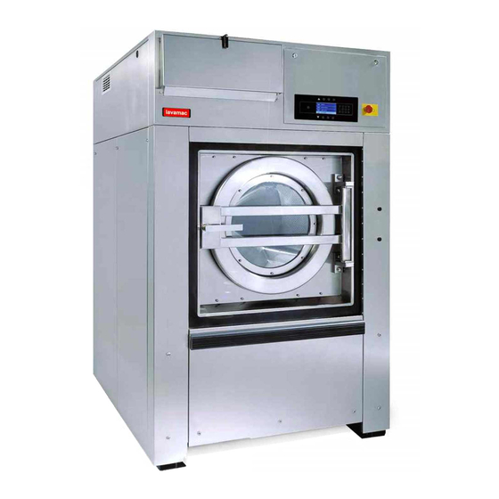
- Page 1 High spin industrial washer extractors 33kg 40kg 55kg 80kg 100kg 120kg Original user's manual Original installation and maintenance manual 554515 A Publication date: 1 Feb 2014...
-
Page 3: Table Of Contents
USER'S MANUAL 1. TABLE OF CONTENTS 1. TABLE OF CONTENTS ....................3 2. WARNINGS AND LABELS ................... 4 2.1. INSTRUCTIONS FOR MAINTENANCE, ADJUSTMENT AND SAFETY OF PEOPLE......5 3. SYMBOLS ON THE MACHINE (DEPENDING ON THE MACHINE MODEL) ....6 4. OPERATION INSTRUCTION ..................8 4.1. -
Page 4: Warnings And Labels
2. WARNINGS AND LABELS TO MINIMIZE THE RISK OF FIRE, INJURY BY ELECTRIC SHOCK OR SERIOUS INJURIES TO PEOPLE OR PROPERTY DAMAGE, PLEASE READ AND FOLLOW THE FOLLOWING INSTRUCTIONS: – This English version is original language version. Without this original version, these instructions are incomplete. –... -
Page 5: Instructions For Maintenance, Adjustment And Safety Of People
WARNING! DO NOT TOUCH THE DOORGLASS UNTIL CYCLE HAS BEEN COMPLETED. DO NOT OPEN DOOR UNTIL CYLINDER REMAINS STOPPED AND WATER HAS BEEN DRAINED FROM CYLINDER. DO NOT PUT ARTICLES SOILED WITH EXPLOSIF SOLVENTS AND/OR DANGEROUS CHEMICAL PRODUCTS IN THE MACHINE. THIS MACHINE SHOULD NOT BE USED BY CHILDREN. DO NOT LET CHILDREN PLAY IN, ON, OR AROUND THE MACHINE. -
Page 6: Symbols On The Machine (Depending On The Machine Model)
3. SYMBOLS ON THE MACHINE (DEPENDING ON THE MACHINE MODEL) Caution, dangerous electrical tension, Do not put your hands on the marked area electrical devices Do not close or cover Caution, other danger, read and follow written instructions In case of emergency press the emergency button to stop the machine Caution - Increased temperature The holes to be drilled not punched... - Page 7 Xcontrol plus 33-40-55 / 80-100-120 kg 80-100-125 / 180-230-275 lb SELECTION NO START DECREASING THE TIME (ADVANCE function) SEQUENCE SELECTION YES STOP (program interruption) INCREASING THE TIME SEQUENCE INFO CONFIRM THE SELECTION (overview of available wash programs and program information) CANCEL THE SELECTION SERVIS (servicing information) MOVE UP,...
-
Page 8: Operation Instruction
4. OPERATION INSTRUCTION 4.1. BEFORE WASHING Sort the linen according to temperature and instructions determined by fabric manufacturer. Check if there aren‘t any strange objects between the linen like nails, screws, needles, etc. to prevent the washer-extractor or linen damage. Turn sleeves of shirts, blouses, etc. inside out. To get a better washing result mix the bigger and smaller pieces of linen and put them into the washer separately. -
Page 9: Closing The Door
4.4. CLOSING THE DOOR WARNING! NEVER PUT FINGERS BETWEEN DOOR SEALING AND DRUM, AVOID POSSIBLE INJURY! Turn the handle up. Before start up, make sure the door is properly latched. Machine with tilting system: Before you start a new cycle, the machine must be in its basic position. If the door is closed before the machine reaches the basic position, a warning is displayed. -
Page 10: Start The Washer
For washing machines connected to liquid soap supply system. Check if the liquid soap supply system is in operation and if there is sufficient quantity of liquid soap. Standard wash programs versus custom made wash programs. This explanation is only valid for standard wash programs. For custom made programs, it is possible that other dispensers have been selected. -
Page 11: End Of Wash Cycle
4.9. END OF WASH CYCLE WARNING! WHEN THE POWER SUPPLY HAS BEEN CUT, THE DOOR WILL BE AUTOMATICALLY BLOCKED AGAINST OPENING. AFTER COOLING DOWN THE WASHING BATH, THE DOOR CAN BE OPENED ACCORDING TO THE MACHINE MAINTENANCE INSTRUCTIONS. The wash cycle time is counted down to zero on the display. After the completion of the wash cycle, the door lock gets deactivated (it unlocks) and the display shows the message “UNLOAD”. -
Page 12: First Service At Technical Problem
5. FIRST SERVICE AT TECHNICAL PROBLEM N° Failure Failure Action Fault occurrence message No Drain End Drain failure Full Stop + tumble Draining Whole cycle, revolutions Safety switch Tilt Fault Full stop + tumble under the distribution activated revolutions level. Safety switch activated during Imbalance... - Page 13 N° Failure Failure Action Fault occurrence message Verification fault Verify Par frequency inverter Don’t start At loading parameters parameters Wrong software Wrong Softw Don’t start New software version version Unbalance Reduction of spinning detection system sequence revolutions. Imbalance Spinning sequence activated.
- Page 14 N° Failure Failure Action Fault occurrence message Internal memory Traceability function, whole TRACEYBILIT Error data for For Info only E550 cycle Y Write traceability Internal Traceability function, whole TRACEYBILIT E551 Traceability For Info only cycle Y Full memory is full E560 Errors in communication Only in Advanced menu...
-
Page 15: Contents
INSTALLATION AND MAINTENANCE MANUAL 1. CONTENTS 1. CONTENTS........................15 2. IMPORTANT SAFETY INSTRUCTIONS ..............16 2.1. SYMBOLS ON THE MACHINE......................19 2.2. IMPORTANT INFORMATION BEFORE INSTALLATION ..............19 3. TECHNICAL SPECIFICATIONS ................... 20 3.1. WASHERS 33-40-55 kg / 80-100-125 lb ...................20 3.2. WASHERS 80-100-120 kg / 180-230-275 lb ..................22 3.3. -
Page 16: Important Safety Instructions
2. IMPORTANT SAFETY INSTRUCTIONS WARNING - SAVE THESE INSTRUCTIONS FOR LATER USE. Failure to comply with the instructions may lead to incorrect use of the appliance, and may result in risk of fire, bodily injuries or death and/or damage to the laundry and/or the appliance. WARNING - Read the IMPORTANT SAFETY INSTRUCTIONS in this manual carefully before operating the appliance. - Page 17 TEMPERATURE IN WASHING MACHINE TUB: The electronic controller uses the temperature sensor in the tub to control the temperature of the washing bath. There are a lot of things that have influence on the temperature measurement. Therefore the temperature control of the washing bath is not very precise. ...
- Page 18 WARNING! ALTHOUGH THE APPLIANCE MAY BE IN THE „OFF“ POSITION, THERE IS STILL ELECTRICAL POWER TO THE SWITCH SUPPLY TERMINALS. WARNING! WHEN POWER SUPPLY HAS BEEN SWITCHED OFF WAIT FOR AT LEAST 10 MINUTES BEFORE STARTING INSPECTION OR SERVICING THE WASHER. BEFORE STARTING INSPECTION OF FREQUENCY INVERTER, CHECK FOR RESIDUAL VOLTAGE ACROSS MAIN CIRCUIT TERMINALS + AND -.
-
Page 19: Symbols On The Machine
2.1. SYMBOLS ON THE MACHINE See User's manual. 2.2. IMPORTANT INFORMATION BEFORE INSTALLATION FOR TRANSPORTATION AND STORAGE IN CASE OF TRANSPORTATION AND STORAGE, WATCH COMPONENTS PROTRUDING FROM THE CONTOUR LINE OF MACHINE (DOOR LOCKS ETC.), TO AVOID INJURIES. – Never push, pull or exert pressure on components protruding from the machine contour line (controls, door locks etc.). -
Page 20: Technical Specifications
3. TECHNICAL SPECIFICATIONS 3.1. WASHERS 33-40-55 kg / 80-100-125 lb MACHINE kg / lb 33 / 80 40 / 100 55 / 125 MACHINE DIMENSIONS Width mm / inch 1195 / 47.04 1195 /47.04 1195 / 47.04 Depth mm / inch 1330 / 52.4 1430 / 56.3 1610 / 63.4... - Page 21 MACHINE kg / lb 33 / 80 40 / 100 55 / 125 El. heating 24kW (200- 240V) El. heating 24kW (380- 415V) El. heating 24kW (440- 480V) El. heating 36kW (200- 240V) El. heating 36kW (380- 480V) El. heating 54kW (220-240V) El.
-
Page 22: Washers 80-100-120 Kg / 180-230-275 Lb
3.2. WASHERS 80-100-120 kg / 180-230-275 lb MACHINE kg / lb 80 / 180 100 / 230 120 / 275 MACHINE DIMENSIONS Width mm / inch 1495 / 58.86 1790 / 70.47 1855 / 73.03 Depth mm / inch 1940 / 76.38 2005 / 78.94 2085 / 82.09 Height... - Page 23 MACHINE kg / lb 80 / 180 100 / 230 120 / 275 CONNECTION DATA Water inlet connection inch 3 x BSP 1 ½“ Water pressure range MPa / bar / PSI 0.1- 0.8 / 1 - 8 / 14.5 - 116 Recommended water pressure MPa / bar / PSI...
-
Page 24: Dimensions And Components Of The Washers 33-40-55 Kg / 80-100-125 Lb
3.3. DIMENSIONS AND COMPONENTS OF THE WASHERS 33-40-55 kg / 80-100-125 lb FRONT SIDE LEFT SIDE REAR SIDE Figure 3.3. – Machines 33-40-55 kg / 80-100-125 lb 1. Operator panel 10. Hose connection soap supply 2. Tub ventilation: Ø 60mm / 2.4“ 11. - Page 25 MACHINE kg / lb 33 / 80 40 / 100 55 / 125 mm / inch 1195 / 47,04 1195 / 47,04 1195 / 47,04 mm / inch 1361 / 53,58 1361 / 53,58 1361 / 53,58 (1, 2) mm / inch 1905 / 75 1905 / 75 1905 / 75...
-
Page 26: Dimensions Of The Washers 40-55 Kg / 100-125 Lb With Forward Tilting
3.4. DIMENSIONS OF THE WASHERS 40-55 kg / 100-125 lb WITH FORWARD TILTING – ON REQUEST COMPRESSED AIR INLET DOOR SECURING: LATCH FRONT SIDE LEFT SIDE REAR SIDE VIEW FROM ABOVE LEFT SIDE Figure 3.4. – Machines 40-55 kg / 100-125 lb with forward tilting Machine kg / lb 40 / 100... -
Page 27: Dimensions And Components Of The Washers 80-100-120 Kg / 180-230-275 Lb
3.5. DIMENSIONS AND COMPONENTS OF THE WASHERS 80-100-120 kg / 180-230-275 lb RIGHT SIDE FRONT SIDE REAR SIDE LEFT SIDE WITH WEIGHING Figure 3.5. – Machines 80-100-120 kg / 180-230-275 lb, (dimensions are stated in mm / inches) 1. Box of electrical components 10. - Page 28 MACHINE kg / lb 80 / 180 100 / 230 120 / 275 mm / inch 1495 / 58.86 1790 / 70.47 1855 / 73.03 mm / inch 2010 / 79.13 2060 / 81.10 2085 / 82.09 mm / inch 1940 / 76.38 2005 / 78.94 2085 / 82.09...
-
Page 29: Dimensions Of The Washers 80-100-120 Kg / 180-230-275 Lb With Forward Tilting
3.6. DIMENSIONS OF THE WASHERS 80-100-120 kg / 180-230-275 lb WITH FORWARD TILTING – ON REQUEST COMPRESSED AIR INLET DOOR SECURING: FINGER BACKSTOP FINGER COMPLETE FRONT SIDE LEFT SIDE REAR SIDE VIEW FROM ABOVE LEFT SIDE Figure 3.6. – Machines 80-100-120 kg / 180-230-275 lb with forward tilting Machine kg / lb 80 / 180... -
Page 30: Dimensions Of The Washers 80-100-120 Kg / 180-230-275 Lb With Two-Way Tilting (Forward And Backward)
3.7. DIMENSIONS OF THE WASHERS 80-100-120 kg / 180-230-275 lb WITH TWO-WAY TILTING (FORWARD AND BACKWARD) – ON REQUEST COMPRESSED AIR INLET DOOR SECURING: FINGER BACKSTOP FINGER COMPLETE FRONT SIDE LEFT SIDE REAR SIDE VIEW FROM ABOVE LEFT SIDE (FORWARD TILTING) LEFT SIDE (BACKWARD TILTING –... -
Page 31: Installation
4. INSTALLATION 4.1. HANDLING, TRANSPORT AND STORAGE TRANSPORT AND STORAGE WARNING! FORKS OF LIFT TRUCK MUST HAVE SUFFICIENT LENGTH (SEE FIGURE 4.1.). Use a lift truck or a manual skid cart for handling with the machine in transporting package. – If possible, leave the machine in the transporting package or at least let it set on the transporting wooden skid until the time of final installation on the foundation according the chapter 4.3. -
Page 32: Space Requirements
4.2. SPACE REQUIREMENTS REQUIRED MACHINE WORKING CONDITIONS See chapter „3. TECHNICAL SPECIFICATION“. The washer must not be installed or stored in an area where it will be exposed to water and/or weather. Avoid damp conditions where water or moisture could run down the walls and covers of the washer or cover the floor around the washer. - Page 33 With forward and Without tilting Wihout tilting With forward tilting With forward tilting MACHINE backward tilting, Without weighing With weighing Without weighing With weighing kg / lb Without weighing anchoring anchoring anchoring not to be must be anchored 80 / 180 recommended recommended recommended...
- Page 34 Figure 4.3.A. – Machines 33-40-55 kg / 80-100-125 lb without weighing system and tilting system 1. Machine line of contour 2. Machine footing 3. Waste sump 4. Anchoring bolt – not supplied with the machine, (on request) 5. Draining elbow 6.
- Page 35 Figure 4.3.B. – Machines 80-100-120 kg / 180-230-275 lb without weighing system and tilting system 1. Machine line of contour 2. Machine footing 3. Waste sump 4. Anchoring bolt – not supplied with the machine, (on request) 5. Draining hose 6.
- Page 36 MACHINE kg / lb 33 / 80 40 / 100 55 / 125 80 / 180 100 / 230 120 / 275 mm / inch 970 / 38,18 1070 / 42,13 1250 / 49,21 1310 / 51.57 1388 / 54,64 1400 / 55,11 mm / inch 930 / 36.61...
- Page 37 WEIGHING SYSTEM INSTALLATION – ON REQUEST 1. Lift up the machine. 2. Install load sensors – figures 4.3.C, 4.3.D. 3. Check that all the rubber feet with load sensors are correctly placed on the machine frame and tightened. 4. Place the machine in the required position carefully - so that it is not subjected to any impact or shock.
- Page 38 MACHINE ANCHORING 40-55 kg / 100-125 lb WITH FORWARD TILTING – ON REQUEST Drill a hole for the anchoring bolt based on the required machine placement – see figures 4.3.F and G. Remove the upper nut and washer from the anchor bolt. Place the anchor bolt into the pre-drilled hole, place the machine in position (the bolt goes through the air spring plate) attach the washer and nut back again and tighten.
- Page 39 ADJUSTMENT AND ANCHORING OF MACHINES 80-100-120 kg / 180-230-275 lb WITH FORWARD TILTING – ON REQUEST 1. The lifting system adjustment applies to both the machine sides. 2. For the adjustment of the distance between the air spring plate side, see figure 4.3.I., pos.1 and the machine frame –...
- Page 40 ANCHORING BOLT ANCHORING BOLT (NOT SUPPLIED WITH THE (NOT SUPPLIED MACHINE, WITH THE MACHINE, ON REQUEST) ON REQUEST) REAR SIDE REAR SIDE VIEW FROM ABOVE VIEW FROM ABOVE FRONT SIDE FRONT SIDE Figure 4.3.K – Machines 80-100-120 kg / 180-230-275 lb ANCHORING BOLT with forward tilting and with weighing system –...
- Page 41 ADJUSTMENT AND ANCHORING OF MACHINES 80-100-120 kg / 180-230-275 lb WITH TWO-WAY TILTING (FORWARD AND BACKWARD) – ON REQUEST 1. The lifting system adjustment applies to both the machine sides. 2. Adjust the distance between the air spring plate side (figure 4.3.L., pos.1) and the machine frame (pos. 2) to 133 mm / 5.24”...
- Page 42 ANCHORING BOLT MACHINE kg / lb 80 / 180 100 / 230 120 / 275 (SUPPLIED WITH THE 1486 / 58.50 1780 / 70.08 1846 / 72.68 MACHINE) 1010 / 39.76 1010 / 39.76 1010 / 39.76 62 / 2.44 64 / 2.52 64 / 2.52 316 / 12.44...
-
Page 43: Connections
4.4. CONNECTIONS WATER CONNECTION The washers are equipped with ¾“, 1“ or 1½“ BSP (British Standard Pipe Thread) hot and cold water inlet valves, indicated by a sticker next to the inlet. For connection dimensions see figures 3.3., 3.5. Use the water inlet hoses that accompany the washer as they are properly adapted to the water valves and appliance. - Page 44 flexible hose with silicon cement. Secure the elbow or the hose with a clamp. Cover the waste sump with a proper cover. The waste channel must be located lower than the drain outlets because the water discharges from the machines by gravity. Do not reduce the diameter of the machine drain pipes. The main waste channel or pipeline must have such a capacity that it can take away the drained water from all connected machines at the same time.
- Page 45 – Make sure the supply voltage is always within the limits specified in the „3. Technical specification“ table in all circumstances. When you have long distances in the electrical installation, it may be necessary to use bigger cables to reduce the voltage drop. –...
- Page 46 SUPPLY CABLE The supply cable is not delivered with the machine. Specifications: – Conductors with copper cores – Stranded conductors are strongly recommended (flexible wiring) to avoid conductor breaking because of vibration – THE CROSS SECTION DEPENDS ON THE USED SUPPLY PROTECTION DEVICE. SEE TABLE 4.4., FOR THE MINIMAL CROSS SECTION –...
- Page 47 Power supply protection device Min phase conductor Min Protection conductor nominal current (US) section in mm (AWG) section in mm (AWG) Automatic circuit breakers Fuses 16 (15) 10 (10) 1.5 (AWG 15) 1.5 (AWG 15) 20 (20) 16 (15) 2.5 (AWG 13) 2.5 (AWG 13) 25 (-) 20 (20)
- Page 48 WASHER PROTECTIVE EARTH CONNECTION AND EQUIPOTENTIAL BONDING Independent of the supply cable, the washer must be connected to the laundry protective earth system with a separate conductor. The protection conductor, enabling this connection, is not included with the washer. If there are other washers/appliances with exposed conductive parts, which can be touched simultaneously, make sure to make equipotential bonding between all these appliances.
- Page 49 LIQUID SOAP CONNECTION MACHINES 80-100-120 kg / 180-230-275 lb Connection point for soap supply, see figure 3.5., pos.9. MACHINES 33-40-55 kg / 80-100-125 lb By default the machines are produces in version: With liquid soap General : Always use liquid soap pumps that have a flow rate high enough to bring the requested quantity into the washer in less than 30 sec.
- Page 50 ELECTRONIC CONTROLLER WITH BLUE PCB AND GRAPHICAL DISPLAY For electric connection of supply control signals a plastic box is available on the back side of the machine (see figure 4.4.H., pos.1) with the terminal box with LED signalization of activation of the respective pump, (pos.2). Under the terminal box there is a label for electric connection.
-
Page 51: Putting The Machine Into Service
4.5. PUTTING THE MACHINE INTO SERVICE WARNING! THE TRANSPORT BRACES MUST BE REMOVED PRIOR PUTTING YOUR MACHINE INTO SERVICE. OTHERWISE YOUR WASHING MACHINE CAN BE SERIOUSLY DAMAGED! MACHINES 33-40-55 kg / 80-100-125 lb, figure 4.5.A Before you put the machine into operation, remove the three striking color transport braces securing the vibrating machine components during the transport. - Page 52 MACHINES 80-100-120 kg / 180-230-275 lb, figure 4.5.C Before you put the machine into operation, remove the six striking color transport braces securing the vibrating machine components during the transport. The three braces are placed on the left side of the machine and three braces are placed on the right side of the machine, accessible after removal of the side covers.
- Page 53 CHECKING BEFORE PUTTING INTO SERVICE 1. A check of the transport braces removal. 2. Removal of the cabinet protective foil. 3. A check if the waste sump is ready for water drainage. 4. A check of the protective connection (earth connection) - „PE“ or „PEN“. 5.
-
Page 54: Maintenance
5. MAINTENANCE WARNING! ALWAYS FOLLOW SAFETY INSTRUCTIONS! DO NOT BYPASS ANY SAFETY DEVICES OR THEIR PARTS. ANY INTERFERENCE TO THE MACHINE FUNCTIONS AND CONSTRUCTION ARE PROHIBITED! USE THE PROPER CHEMICAL AGENTS WHICH AVOID CALCIUM SEDIMENTS ON HEATING ELEMENTS AND OTHER MACHINE PARTS. DISCUSS THIS ISSUE WITH YOUR SUPPLIER OF WASHING PRODUCTS. THE MANUFACTURER OF THE MACHINE IS NOT RESPONSIBLE FOR THE DAMAGE OF HEATING ELEMENTS AND OTHER MACHINE PARTS DUE TO CALCIUM SEDIMENTS. -
Page 55: Every 6 Months Or After 1000 Working Hours
5.5. EVERY 6 MONTHS OR AFTER 1000 WORKING HOURS 1. Clean the filters with water and steam inlets by chapter 5.10. 2. Remove the rear machine cover and check the condition and tightness of the V-belts (chapter 5.9.). WARNING! BEFORE REMOVING TOP OR BACK PANEL OF THE MACHINE, SWITCH POWER OFF AND WAIT FOR AT LEAST 10 MINUTES. - Page 56 SENSIBILITY ADJUSTMENT, MACHINES 80-100-120 kg / 180-230-275 lb, FIGURE 5.6.B 1. Set a distance 12 mm / 0.47“ between the limiters (2). 2. By moving the vibration switch (4) on the holder (6) to the left, you will decrease the sensibility and to the right you increase it (direction A).
- Page 57 SIDE VIEW FRONT VIEW Figure 5.6.A. – Machines 33-40-55 kg / 80-100-125 lb 1. Front face of the drum 5. Vibration switch 2. Limiter 6. Adjusting nut 3. Bushing 7. Vibration switch holder 4. Switchboard bottom FRONT SIDE RIGHT SIDE Figure 5.6.B.
-
Page 58: Tightening Moments
5.7. TIGHTENING MOMENTS WARNING! REGULARLY, ONCE IN THREE MONTHS OR EVERY 500 WORKING HOURS (WHICH EVER COMES FIRST) INSPECT THE TIGHTNESS OF THE BOLTS! If anyone of the bolts has been damaged, exchange it with the bolt of the same strength value marked on its head. - Page 59 MACHINES 80-100-120 kg / 180-230-275 lb TIGHTENING MOMENTS VALUES OF BOLTS AND NUTS FOR MACHINES 80-100-120 kg / 180-230-275 lb, figure 5.7.B BOLT AMOUNT TIGHTENING TIGHTENING MACHINE DIMENSION (NUT) (pcs) MOMENT (Nm) MOMENT (lbf.ft) 80 kg / 180 lb M16x70 100 kg / 230 lb M20x70 120 kg / 275 lb...
-
Page 60: Lubrication
5.8. LUBRICATION WARNING! DO THE LUBRICATION WORK ONLY WHEN THE MAIN SWITCH IS OFF AND ALL COMPONENTS HAVE BEEN STOPPED! (IF NOT STATED OTHERWISE IN FOLLOWING INSTRUCTION). Every time you use a grease gun especially for greasing bearings and seals, do it slowly - not faster than 5 strokes in 1 minute. -
Page 61: Driving Mechanism
PNEUMATIC LUBRICATOR, WASHERS 80-100-120 kg / 180-230-275 lb Fill the lubricator pot with approximately 23 cm³ of oil. Recommended type of oil: non-detergent and without aggressive additives, viscosity VG32 (ISO 3448). e.g.: oil for pneumatic devices or hydraulic oil. Pressure regulator Condensation trap Lubricator pot Figure 5.8.B. -
Page 62: Water And Steam Filters
BELT REPLACEMENT NEVER USE A CROWBAR TO TAKE OFF THE BELTS OVER THE PULLEY GROOVES. Loosen the bolts of tightening pulley on the drum rear wall and the adjusting screw for taking the belts off. Always change a complete set of the belts. Always the same type of the changed belts in the set is required. If the pulleys are damaged, replace them. -
Page 63: Thrust Of Door Seal
5.11. THRUST OF DOOR SEAL If there is a water leakage around the door it is necessary to find out if the problem has been caused due to the door shift out of its position or if the door seal thrust should be adjusted. In some cases the door seal has to be replaced. -
Page 64: Spring Unit
ADJUSTING ON THE SIDE OF THE DOOR HINGE, FIGURES 5.11.A., 5.11.B IF THE ADJUSTMENT AT THE DOOR HANDLE SIDE IS INSUFFICIENT, IT IS NECESSARY TO PERFORM ADJUSTMENT AT THE DOOR HINGE SIDE. 1. Loosen two bolts (6) fastening the top door hinge (7). BE CAREFUL TO AVOID POSSIBLE FALLING OF THE DOOR WITH LOOSENED HINGE TO THE FLOOR. -
Page 65: Replacement Washer Fuses
MACHINES 80-100-120 kg / 180-230-275 lb Adjusted by manufacturer. 1. Spring unit 2. Machine frame 3. Suspended part 4. Spring suspension eyes 5. Guiding rods Figure 5.12.B. – Machines 80-100-120 kg / 180-230-275 lb 5.13. REPLACEMENT WASHER FUSES FUSE VALUES The correct values of fuses can be found in the vicinity of the fuse holders and on the electrical scheme and delivered with the machine. -
Page 66: Trouble Shooting Aids
6. TROUBLE SHOOTING AIDS 6.1. DOOR BLOCKING DESCRIPTION OF DOOR LOCK FUNCTION The door lock has been designed as a compact unit. Its function is to secure the door against opening during the washing cycle. When the cycle is finished unlocking is done automatically by a programmer. The lock has been blocked also during the failure situations e.g. -
Page 67: Error Indication Shown On Display
Figure 6.1.A. – Machines 33-40-55 kg / 80-100-125 lb, view from above Figure 6.1.B. – Machines 80-100-120 kg / 180-230-275 lb, door lock cover 6.2. ERROR INDICATION SHOWN ON DISPLAY See User's manual, chapter 5. See Programming manual, chapter „Troubleshooting“. 554515_A_PUB_DATE_1_FEB_2014.DOC INSTALLATION AND MAINTENANCE MANUAL... -
Page 68: List Of Recommended Spare Parts
7. LIST OF RECOMMENDED SPARE PARTS List of recommended spare parts: – drain valve – 1-way inlet valve – 2-way inlet valve – 3-way inlet valve – steam valve – door lock microswitch – door lock coil – fuses – thermostat sensor –... -
Page 69: Putting The Machine Out Of Service
8. PUTTING THE MACHINE OUT OF SERVICE If the machine is out of service, possibly replaced, follow the instructions. 8.1. DISCONNECTING THE MACHINE 1. Switch off the external electric power inlet to the machine. 2. Turn off the main switch on the machine rear. 3. - Page 70 IMPORTANT ! MACHINE TYPE: PROGRAMMER: ELECTRONIC TIMER INSTALLATION DATE: INSTALLATION CARRIED OUT BY: SERIAL NUMBER: ELECTRICAL DETAILS: .....VOLT....PHASE....HZ NOTE: ANY CONTACTS WITH YOUR DEALER REGARDING MACHINE SAFETY, OR SPARE PARTS, MUST INCLUDE THE ABOVE IDENTIFICATION. MAKE CERTAIN TO KEEP THIS MANUAL IN A SECURE PLACE FOR FUTURE REFERENCE.
Need help?
Do you have a question about the LH-550 and is the answer not in the manual?
Questions and answers