Table of Contents
Advertisement
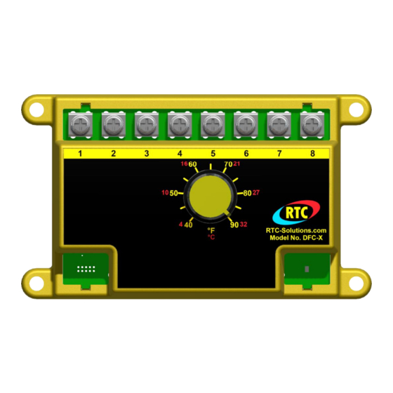
Model No. DFC-X
DIRECT FIRED DIGITAL TEMPERATURE CONTROL INSTALLATION,
OPERATION, AND MAINTENANCE MANUAL
This manual covers the following products:
DFC-X
Direct fired control with integral 40-90°F (4-32°C) dial 0-24VDC output
TS-01
Temperature senor 40-250°F (4-121°C)
DFTD
Temperature dial 5 selectable ranges
RDU
Remote display unit
DAT-12
Discharge air tube
PWM-10V
PWM to 10V output converter
Table of Contents
Overview ..................................................................................................................................................................................................................................................... 2
Specifications .............................................................................................................................................................................................................................................. 2
Power Requirements.............................................................................................................................................................................................................................. 2
DFC-X Ambient Temperature Limits .................................................................................................................................................................................................. 2
TS-01/DFTD Ambient Temperature Limits ....................................................................................................................................................................................... 2
Accuracy .................................................................................................................................................................................................................................................. 2
Installation .................................................................................................................................................................................................................................................. 2
Wiring .......................................................................................................................................................................................................................................................... 2
Standard control with remote setpoint ................................................................................................................................................................................................ 2
Standard control with integral setpoint .............................................................................................................................................................................................. 3
Optional room space control ................................................................................................................................................................................................................ 4
Optional multiple setpoint temperature control ................................................................................................................................................................................ 5
Operation .................................................................................................................................................................................................................................................... 5
Start up .................................................................................................................................................................................................................................................... 5
Sequence of operation............................................................................................................................................................................................................................ 5
Calibration .............................................................................................................................................................................................................................................. 5
Troubleshooting ..................................................................................................................................................................................................................................... 5
LED Code Chart .................................................................................................................................................................................................................................... 6
TS-01 and DFTD Resistance chart ........................................................................................................................................................................................................ 6
DOC# T0012 3.26.2019 DFC-X O&M
Ph. (877) 351-4702
Fax (919) 400-4165
Support 877-351-4702
1
www.RTC-Solutions.com
Email:info@RTC-Solutions.com
4370 Oakes Road, Suite 700
Davie, FL 33314
Advertisement
Table of Contents

Related Manuals for RTC DFC-X

Summary of Contents for RTC DFC-X
- Page 1 PWM to 10V output converter Table of Contents Overview ..................................................2 Specifications ................................................2 Power Requirements.............................................. 2 DFC-X Ambient Temperature Limits ........................................2 TS-01/DFTD Ambient Temperature Limits ....................................... 2 Accuracy .................................................. 2 Installation .................................................. 2 Wiring ..................................................2 Standard control with remote setpoint ........................................ 2 Standard control with integral setpoint ......................................
- Page 2 (TS-01), the direct fired control (DFC-X), and the direct fired temperature dial (DFTD) or the remote display unit (RDU). The DFC-X auto detects if there is a remote dial connected. When a remote is not connected, the DFC-X uses the internal setpoint. The system compares the discharge temperature of the heating unit to the set point dial 40 times per second insuring accurate and repeatable temperature control.
- Page 3 PWM-10V We do offer a PWM output converter to connect the DFC-X to a 0-10V actuator rather than a 24VDC solenoid valve. If you are utilizing the PWM-10V to connect to a motorized actuator or any other device with it’s own power supply, than be sure the DFC-X has its own isolated transformer separate from the power source for the actuator, or the control may be damaged.
- Page 4 For proportional room space control, the DFC-X may be connected as shown in Figure 6. See RDU literature for details.
- Page 5 Start up Setting low fire – The minimum firing rate may be set by removing the wire from the terminal number 6 on the DFC-X control. This disconnects the power to the control valve. Refer to the control valve manufacturer’s literature for this adjustment. You can also set low fire by entering Maintenance Mode as described below.
- Page 6 If there is no fault light but the system is not modulating properly you may check the control output by repeating the start up procedure and measuring terminals 5 and 6 on the DFC-X as stated below.
Need help?
Do you have a question about the DFC-X and is the answer not in the manual?
Questions and answers