Lenovo ThinkCentre M70q Hardware Maintenance Manual
Hide thumbs
Also See for ThinkCentre M70q:
- Hardware maintenance manual (90 pages) ,
- Setup manual (10 pages) ,
- User manual (106 pages)
Table of Contents
Advertisement
Advertisement
Table of Contents

Related Manuals for Lenovo ThinkCentre M70q


Summary of Contents for Lenovo ThinkCentre M70q
- Page 1 M70q Hardware Maintenance Manual...
- Page 2 First Edition (February 2021) © Copyright Lenovo 2021. LIMITED AND RESTRICTED RIGHTS NOTICE: If data or software is delivered pursuant to a General Services Administration “GSA” contract, use, reproduction, or disclosure is subject to restrictions set forth in Contract No. GS-...
-
Page 3: Table Of Contents
Notices and trademarks ..1 System board ....Removing and installing hardware ..© Copyright Lenovo 2021... - Page 4 M70q Hardware Maintenance Manual...
-
Page 5: About This Manual
Important: This manual is intended only for trained service technicians who are familiar with ThinkCentre computers. Use this manual along with the advanced diagnostic tests to troubleshoot problems effectively. Before servicing a ThinkCentre computer, be sure to read and understand Chapter 1 “Important safety information” on page 1. © Copyright Lenovo 2021... - Page 6 M70q Hardware Maintenance Manual...
-
Page 7: Chapter 1. Important Safety Information
Avoid contact with hot components inside the computer. During operation, some components become hot enough to burn the skin. Before you open the computer cover, turn off the computer, disconnect power, and wait approximately 10 minutes for the components to cool. © Copyright Lenovo 2021... -
Page 8: Electrical Safety
Electrical safety CAUTION: Electrical current from power, telephone, and communication cables can be hazardous. To avoid personal injury or equipment damage, disconnect the attached power cords, telecommunication systems, networks, and modems before you open the computer covers, unless instructed otherwise in the installation and configuration procedures. -
Page 9: Safety Inspection Guide
• Do not service the following parts with the power on when they are removed from their normal operating places in a machine: – Power supply units – Pumps – Blowers and fans – Motor generators and similar units. (This practice ensures correct grounding of the units.) •... -
Page 10: Handling Electrostatic Discharge-Sensitive Devices
8. Check that the power-supply cover fasteners (screws or rivets) have not been removed or tampered with. Handling electrostatic discharge-sensitive devices Any computer part containing transistors or integrated circuits (ICs) should be considered sensitive to electrostatic discharge (ESD). ESD damage can occur when there is a difference in charge between objects. Protect against ESD damage by equalizing the charge so that the machine, the part, the work mat, and the person handling the part are all at the same charge. - Page 11 • Italian • Korean • Spanish DANGER Electrical current from power, telephone and communication cables is hazardous. To avoid a shock hazard: • Do not connect or disconnect any cables or perform installation, maintenance, or reconfiguration of this product during an electrical storm. •...
- Page 12 CAUTION: When laser products (such as CD-ROMs, DVD-ROM drives, fiber optic devices, or transmitters) are installed, note the following: • Do not remove the covers. Removing the covers of the laser product could result in exposure to hazardous laser radiation. There are no serviceable parts inside the device. •...
- Page 13 Chapter 1 Important safety information...
- Page 14 ≥18 kg (37 lb) ≥32 kg (70.5 lb) ≥55 kg (121.2 lb) M70q Hardware Maintenance Manual...
- Page 15 PERIGO A corrente elétrica proveniente de cabos de alimentação, de telefone e de comunicações é perigosa. Para evitar risco de choque elétrico: • Não conecte nem desconecte nenhum cabo ou execute instalação, manutenção ou reconfiguração deste produto durante uma tempestade com raios. •...
- Page 16 Quando produtos a laser (como unidades de CD-ROMs, unidades de DVD-ROM, dispositivos de fibra ótica ou transmissores) estiverem instalados, observe o seguinte: • Não remova as tampas. A remoção das tampas de um produto a laser pode resultar em exposição prejudicial à...
- Page 17 Chapter 1 Important safety information...
- Page 18 M70q Hardware Maintenance Manual...
- Page 19 Chapter 1 Important safety information...
- Page 20 DANGER Le courant électrique provenant de l'alimentation, du téléphone et des câbles de transmission peut présenter un danger. Pour éviter tout risque de choc électrique : • Ne manipulez aucun câble et n'effectuez aucune opération d'installation, d'entretien ou de reconfiguration de ce produit au cours d'un orage.
- Page 21 Connexion Déconnexion 1. Mettez les unités HORS TENSION. 1. Mettez les unités HORS TENSION. 2. Commencez par brancher tous les cordons sur les 2. Débranchez les cordons d'alimentation des prises. unités. 3. Débranchez les câbles d'interface des connecteurs. 3. Branchez les câbles d'interface sur des 4.
- Page 22 ≥18 kg (37 lb) ≥32 kg (70.5 lb) ≥55 kg (121.2 lb) ATTENTION: Soulevez la machine avec précaution. ATTENTION: L'interrupteur de contrôle d'alimentation de l'unité et l'interrupteur dubloc d'alimentation ne coupent pas le courant électrique alimentantl'unité. En outre, le système peut être équipé de plusieurs cordonsd'alimentation.
- Page 23 • Die Verbindung zu den angeschlossenen Netzkabeln, Telekommunikationssystemen, Netzwerken und Modems ist vor dem Öffnen des Gehäuses zu unterbrechen, sofern in den Installations- und Konfigurationsprozeduren keine anders lautenden Anweisungen enthalten sind. • Zum Installieren, Transportieren und Öffnen der Abdeckungen des Computers oder der angeschlossenen Einheiten die Kabel gemäß...
- Page 24 Laserstrahlung bei geöffneter Verkleidung. Nicht in den Strahl blicken. Keine Lupen oder Spiegel verwenden. Strahlungsbereich meiden. ≥18 kg ≥32 kg ≥55 kg ACHTUNG: Arbeitsschutzrichtlinien beim Anheben der Maschine beachten. ACHTUNG: Mit dem Netzschalter an der Einheit und am Netzteil wird die Stromversorgung für die Einheit nicht unterbrochen.
- Page 25 Chapter 1 Important safety information...
- Page 26 PERICOLO La corrente elettrica proveniente dai cavi di alimentazione, del telefono e di comunicazione può essere pericolosa. Per evitare il rischio di scosse elettriche: M70q Hardware Maintenance Manual...
- Page 27 • Non collegare o scollegare qualsiasi cavo oppure effettuare l'installazione, la manutenzione o la riconfigurazione del prodotto durante un temporale. • Collegare tutti i fili elettrici a una presa di alimentazione correttamente cablata e dotata di messa a terra. • Collegare alle prese elettriche appropriate tutte le apparecchiature che verranno utilizzate per questo prodotto.
- Page 28 • Non rimuovere gli sportelli. L'apertura di un'unità laser può determinare l'esposizione a radiazioni laser pericolose. All'interno dell'unità non vi sono parti su cui effettuare l'assistenza tecnica. • L'utilizzo di controlli, regolazioni o l'esecuzione di procedure non descritti nel presente manuale possono provocare l'esposizione a radiazioni pericolose.
- Page 29 Chapter 1 Important safety information...
- Page 30 PELIGRO La corriente eléctrica procedente de cables de alimentación, teléfonos y cables de comunicación puede ser peligrosa. Para evitar el riesgo de descarga eléctrica: • No conecte ni desconecte los cables ni realice ninguna tarea de instalación, mantenimiento o reconfiguración de este producto durante una tormenta eléctrica. •...
- Page 31 • No encienda nunca un equipo cuando hay señales de fuego, agua o daños estructurales. • Desconecte los cables de alimentación, los sistemas de telecomunicaciones, las redes y los módems conectados antes de abrir las cubiertas de los dispositivos, a menos que se indique lo contrario en los procedimientos de instalación y configuración.
- Page 32 Algunos productos láser tienen incorporado un diodo láser de clase 3A o clase 3B. Tenga en cuenta lo siguiente: Cuando se abre, queda expuesto a radiación láser. No mire directamente al rayo láser, ni siquiera con instrumentos ópticos, y evite exponerse directamente al rayo láser. ≥18 kg ≥32 kg ≥55 kg...
-
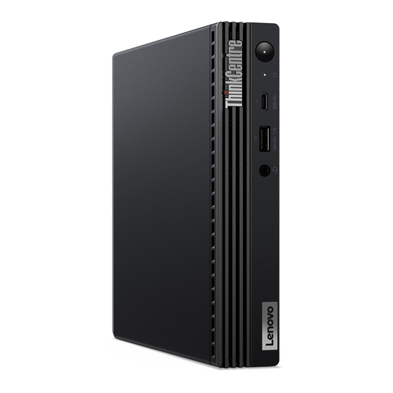
Page 33: Chapter 2. Product Overview
Chapter 2. Product overview Front ® 1. ThinkCentre 2. Power button ® 3. Storage drive activity indicator 4. USB-C (3.2 Gen 1) connector 5. Always On USB 3.2 connector Gen 2 6. Headset connector © Copyright Lenovo 2021... -
Page 34: Rear
Rear 1. Optional connectors* 2. Security-lock slot ® 3. Wi-Fi antenna slot* 4. Ethernet connector 5. USB 3.2 connector Gen 2 6. USB 3.2 connector Gen 1 7. USB 3.2 connector Gen 1 8. HDMI 1.4 out connector ® 9. USB 3.2 connector Gen 1 10. -
Page 35: Chapter 3. Call Amazon Helpdesk
You can get help and information from Amazon Helpdesk. Services not covered • Replacement or use of parts not manufactured for or by Lenovo or nonwarranted parts • Identification of software problem sources • Changes, modifications, or upgrades to device drivers •... - Page 36 M70q Hardware Maintenance Manual...
-
Page 37: Chapter 4. Hardware Removal And Installation
Common tool Isolated tweezers Common tool Hexagonal socket Common tool Silicone grease Consumable tool Polyamide tape Consumable tool Mylar tape Consumable tool Eraser Consumable tool Electrical tape Consumable tool Double-sided tape Consumable tool Conductive tape Consumable tool © Copyright Lenovo 2021... -
Page 38: Major Hardware
Note: The silicone grease can be applied to the surfaces of the microprocessor and heat sink to eliminate air gaps. The hexagonal socket is used to pick up the antenna connectors. Major hardware Your computer contains the following major hardware: M70q Hardware Maintenance Manual... - Page 39 Number Description Computer cover Heat sink System fan Coin-cell battery Internal speaker Antenna bracket Wi-Fi card Wi-Fi card shield Memory module Chassis M.2 solid-state drive Bottom cover Wi-Fi antenna cables Rear Wi-Fi antenna Storage drive cable Storage drive Storage drive bracket System board Microprocessor Dust shield...
-
Page 40: System Board
System board Microprocessor socket Coin-cell battery System fan connector Internal speaker connector Cover presence switch connector (intrusion switch SATA connector (connecting to the storage drive) connector) M.2 Wi-Fi card slot Serial (COM1) connector M70q Hardware Maintenance Manual... -
Page 41: Removing And Installing Hardware
Clear CMOS /Recovery jumper M.2 solid-state drive slot Memory slot (DIMM 2) Memory slot (DIMM 1) Removing and installing hardware This section provides instructions on how to remove and install hardware for your computer. You can expand the capabilities of your computer and maintain your computer by removing or installing hardware. To replace any hardware, contact Amazon Helpdesk. - Page 42 M70q Hardware Maintenance Manual...
-
Page 43: Power Adapter Bracket
4. Reconnect the external cables and power adapter to the corresponding connectors on the computer. Power adapter bracket Prerequisite Before you start, read Chapter 1 “Important safety information” on page 1 and print the following instructions. Replacement procedure 1. Remove any media from the drives and turn off all connected devices and the computer. 2. -
Page 44: Vertical Stand
4. Replace the power adapter bracket. 5. Install the power adapter into the bracket. 6. Reconnect the external cables and power adapter to the corresponding connectors on the computer. Vertical stand Prerequisite Before you start, read Chapter 1 “Important safety information” on page 1 and print the following instructions. - Page 45 4. Reconnect the external cables and power adapter to the corresponding connectors on the computer. Chapter 4 Hardware removal and installation...
-
Page 46: External Optical Drive
External optical drive Prerequisite Before you start, read Chapter 1 “Important safety information” on page 1 and print the following instructions. Replacement procedure 1. Remove any media from the drives and turn off all connected devices and the computer. 2. Disconnect all power cords from electrical outlets and disconnect all cables from the computer. 3. -
Page 47: Vesa Mount Bracket
4. Reconnect the external cables and power adapter to the corresponding connectors on the computer. VESA mount bracket Prerequisite Before you start, read Chapter 1 “Important safety information” on page 1 and print the following instructions. Replacement procedure 1. Remove any media from the drives and turn off all connected devices and the computer. 2. -
Page 48: Dust Shield
4. Reconnect the external cables and power adapter to the corresponding connectors on the computer. Dust shield Prerequisite Before you start, read Chapter 1 “Important safety information” on page 1 and print the following instructions. Replacement procedure 1. Remove any media from the drives and turn off all connected devices and the computer. 2. - Page 49 4. Reconnect the external cables and power adapter to the corresponding connectors on the computer. Chapter 4 Hardware removal and installation...
-
Page 50: Computer Cover
Computer cover Prerequisite Before you start, read Chapter 1 “Important safety information” on page 1 and print the following instructions. Before you open the computer cover, turn off the computer and wait several minutes until the computer is cool. Replacement procedure 1. -
Page 51: Rear Wi-Fi Antenna
8. Place the computer in an upright position. 9. Reinstall the removed parts. Then, reconnect the power adapter and all disconnected cables to the computer. Note: If a locking device is available, use it to lock the computer. Rear Wi-Fi antenna Prerequisite Before you start, read Chapter 1 “Important safety information”... -
Page 52: Internal Speaker
4. Reconnect the external cables and power adapter to the corresponding connectors on the computer. Internal speaker Prerequisite Before you start, read Chapter 1 “Important safety information” on page 1 and print the following instructions. Replacement procedure 1. Remove the computer cover. See “Computer cover” on page 44. 2. -
Page 53: System Fan
3. Replace the internal speaker. 4. Connect the internal-speaker cable to the internal-speaker connector on the system board. 5. Reinstall the removed parts. Then, reconnect the power adapter and all disconnected cables to the computer. System fan Prerequisite Before you start, read Chapter 1 “Important safety information” on page 1 and print the following instructions. -
Page 54: Coin-Cell Battery
5. Connect the system fan cable to the system fan connector on the system board. 6. Reinstall the removed parts. Then, reconnect the power adapter and all disconnected cables to the computer. Coin-cell battery Prerequisite Before you start, read Chapter 1 “Important safety information” on page 1 and print the following instructions. - Page 55 2. Remove the system fan. See “System fan” on page 47. 3. Replace the coin-cell battery. Chapter 4 Hardware removal and installation...
-
Page 56: Storage Drive
4. Reinstall the removed parts. Then, reconnect the power adapter and all disconnected cables to the computer. 5. Turn on the computer and all attached devices. Note: When the computer is turned on for the first time after the coin-cell battery is replaced, an error message might be displayed. - Page 57 Chapter 4 Hardware removal and installation...
-
Page 58: Wi-Fi Card
3. Reinstall the removed parts. Then, reconnect the power adapter and all disconnected cables to the computer. Wi-Fi card Prerequisite Before you start, read Chapter 1 “Important safety information” on page 1 and print the following instructions. Replacement procedure 1. Remove the computer cover. See “Computer cover” on page 44. 2. - Page 59 Chapter 4 Hardware removal and installation...
-
Page 60: Bottom Cover
4. Reinstall the removed parts. Then, reconnect the power adapter and all disconnected cables to the computer. Bottom cover Prerequisite Before you start, read Chapter 1 “Important safety information” on page 1 and print the following instructions. Replacement procedure 1. Remove the computer cover. See “Computer cover” on page 44. 2. -
Page 61: Memory Module
4. Turn over the computer so that the bottom cover is facing down. 5. Reinstall the removed parts. Then, reconnect the power adapter and all disconnected cables to the computer. Memory module Prerequisite Before you start, read Chapter 1 “Important safety information” on page 1 and print the following instructions. -
Page 62: M.2 Solid-State Drive
4. Reinstall the removed parts. Then, reconnect the power adapter and all disconnected cables to the computer. M.2 solid-state drive Prerequisite Before you start, read Chapter 1 “Important safety information” on page 1 and print the following instructions. Attention: • The M.2 solid-state drive is sensitive. Inappropriate handling might cause damage and permanent loss of data. - Page 63 – Do not make the M.2 solid-state drive subject to physical shocks or vibration. Put the M.2 solid-state drive on a soft material, such as cloth, to absorb physical shocks. Replacement procedure 1. Remove the computer cover. See “Computer cover” on page 44. 2.
-
Page 64: Rear Wi-Fi Antenna Cable
4. Reinstall the removed parts. Then, reconnect the power adapter and all disconnected cables to the computer. Rear Wi-Fi antenna cable Prerequisite Before you start, read Chapter 1 “Important safety information” on page 1 and print the following instructions. Replacement procedure 1. - Page 65 Chapter 4 Hardware removal and installation...
-
Page 66: Heat Sink
4. Reinstall the removed parts. Then, reconnect the power adapter and all disconnected cables to the computer. Heat sink Prerequisite Before you start, read Chapter 1 “Important safety information” on page 1 and print the following instructions. The heat sink might be very hot. Before you open the computer cover, turn off the computer and wait several minutes until the computer is cool. -
Page 67: Front Wi-Fi Antenna And Cable
6. Reinstall the removed parts. Then, reconnect the power adapter and all disconnected cables to the computer. Front Wi-Fi antenna and cable Prerequisite Before you start, read Chapter 1 “Important safety information” on page 1 and print the following instructions. Replacement procedure 1. - Page 68 M70q Hardware Maintenance Manual...
-
Page 69: Antenna Bracket
4. Reinstall the removed parts. Then, reconnect the power adapter and all disconnected cables to the computer. Antenna bracket Prerequisite Before you start, read Chapter 1 “Important safety information” on page 1 and print the following instructions. Replacement procedure 1. Remove the computer cover. See “Computer cover” on page 44. 2. -
Page 70: Microprocessor
5. Reinstall the removed parts. Then, reconnect the power adapter and all disconnected cables to the computer. Microprocessor Prerequisite Before you start, read Chapter 1 “Important safety information” on page 1 and print the following instructions. The heat sink and microprocessor might be very hot. Before you open the computer cover, turn off the computer and wait several minutes until the computer is cool. - Page 71 Chapter 4 Hardware removal and installation...
- Page 72 7. Reinstall the removed parts. Then, reconnect the power adapter and all disconnected cables to the computer. M70q Hardware Maintenance Manual...
-
Page 73: System Board
System board Prerequisite Before you start, read Chapter 1 “Important safety information” on page 1 and print the following instructions. Avoid contact with hot components inside the computer. During operation, some components become hot enough to burn the skin. Before you open the computer cover, turn off the computer, disconnect power, and wait approximately 10 minutes for the components to cool. - Page 74 Note: Carefully handle the system board by its edges. 6. Remove the microprocessor from the failing system board, and then install it onto the new system board. See “Microprocessor” on page 64. 7. Install the new system board into the chassis by aligning the six screw holes in the new system board with the corresponding mounting studs on the chassis.
- Page 75 2. Note the orientation of the socket cover, and install one side of the socket cover into the microprocessor socket. Carefully press the other side of the socket cover downward until the socket cover snaps into position. Note: The microprocessor socket cover might look slightly different from the illustration. 3.
- Page 76 M70q Hardware Maintenance Manual...
-
Page 77: Notices And Trademarks
Lenovo representative for information on the products and services currently available in your area. Any reference to a Lenovo product, program, or service is not intended to state or imply that only that Lenovo product, program, or service may be used. Any functionally equivalent product, program, or service that does not infringe any Lenovo intellectual property right may be used instead. - Page 78 Actual results may vary. Users of this document should verify the applicable data for their specific environment. This document is copyrighted by Lenovo and is not covered by any open source license, including any Linux agreement(s) which may accompany software included with this product. Lenovo may update this document at any time without notice.
Need help?
Do you have a question about the ThinkCentre M70q and is the answer not in the manual?
Questions and answers