Table of Contents
Advertisement
Quick Links
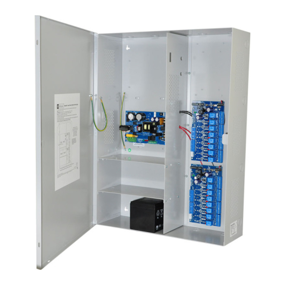
Access Power Controllers
Installation Guide
Models Include:
Maximal3D
- 12VDC @ 5A or 24VDC @ 5.4A.
- Sixteen (16) PTC protected Class 2 Rated power-limited outputs.
Maximal5D
- 12VDC @ 9A.
- Sixteen (16) PTC protected Class 2 Rated power-limited outputs.
Maximal7D
- 24VDC @ 9.4A.
- Sixteen (16) PTC protected Class 2 Rated power-limited outputs.
Rev. MSCB052219
Altronix Corp.
140 58th St. Brooklyn, NY
More than just power.
TM
Advertisement
Table of Contents

Related Manuals for maximal Maximal3D

Summary of Contents for maximal Maximal3D
- Page 1 Access Power Controllers Installation Guide Models Include: Maximal3D - 12VDC @ 5A or 24VDC @ 5.4A. - Sixteen (16) PTC protected Class 2 Rated power-limited outputs. Maximal5D - 12VDC @ 9A. - Sixteen (16) PTC protected Class 2 Rated power-limited outputs.
-
Page 2: Table Of Contents
Access Power Controller Typical Application Diagram (for each ACM8CB) . . . . . . . . . . . . . pg. 7 Maximal3D and Maximal5D Battery Hookup and Tamper Switch Installation . . . . . . . . . . . pg. 8 Maximal7D Battery Hookup and Tamper Switch Installation . -
Page 3: Maximald Series Overview
MaximalD Series Overview: Maximal Access Power/Controllers distribute and switch power to access control systems and accessories . They convert a 115VAC 60Hz input into sixteen (16) independently controlled 12VDC or 24VDC Class 2 Rated PTC protected power-limited outputs . The outputs are activated by an open collector sink or normally open (NO) dry trigger input from an Access Control System, Keypad, Push Button, REX PIR, etc . -
Page 4: Maximald Installation Instructions
There are no user serviceable parts inside. Refer installation and servicing to qualified service personnel. 3 . Select desired DC output voltage by setting SW1 to the appropriate position on the Maximal3D power supply, (Figs. 1 and 1a, pg. 7). Maximal5D power supply is factory set at 12VDC and Maximal7D power supply is factory set at 24VDC . -
Page 5: Maintenance
No DC output . Short circuit or thermal overload condition . No DC output . Loss of AC . Discharged battery . Red (Bat) Battery Status Normal operating condition . Battery fail/low battery . Maximal3D/Maximal5D/Maximal7D Access Power Controllers (PTC) - 5 -... -
Page 6: Access Power Controller Led Diagnostics
L, G, N Connect 115VAC 60Hz to these terminals: L to hot, N to neutral . Maximal3D - 12VDC @ 5A or 24VDC @ 5 .4A to ACM8CB boards (power-limited) + DC – Maximal5D - 12VDC @ 9A to ACM8CB boards (power-limited) . -
Page 7: Power Supply Board Output Voltage Settings
Power Supply Board Output Voltage Settings: Fig. 1a - Maximal3D Power Supply Board OFF - 24V Fig. 1b ON - 12V OFF - 24V ON - 12V Access Power Controller Typical Application Diagram (for each ACM8CB): Fig. 2 Fig. 2a Intact = Dry Input Normally Open (N.O.) -
Page 8: Maximal3D And Maximal5D Battery Hookup And Tamper Switch Installation
Fig. 3 - Maximal3D and Maximal5D Tamper Switch Maximal5D Wire Strap (from Enclosure to Door) Power Supply Board BAT FAIL AC FAIL Input NO C NC NO C NC Line 115VAC, Neutral Earth Ground 60 Hz. *12VDC operation: For 12VDC operation only a single battery is needed. -
Page 9: Maximal7D Battery Hookup And Tamper Switch Installation
12VDC Rechargeable Battery** Battery** (Optional) (Optional) **24VDC operation: Connect two (2) 12VDC batteries in series Fig. 4a Enclosure Edge of Enclosure Tamper Switch (provided) To Access Control Panel or UL Listed Reporting Device Maximal3D/Maximal5D/Maximal7D Access Power Controllers (PTC) - 9 -... -
Page 10: Nec Power-Limited Wiring Requirements For Maximal3D
NEC Power-Limited Wiring Requirements for Maximal3D: Power-limited and non power-limited circuit wiring must remain separated in the cabinet . All power-limited circuit wiring must remain at least 0 .25” away from any non power-limited circuit wiring . Furthermore, all power-limited circuit wiring and non power-limited circuit wiring must enter and exit the cabinet through differ- ent conduits . -
Page 11: Nec Power-Limited Wiring Requirements For Maximal5D
(non power-limited) ACM8CB outputs (power- limited) Battery Connections (non power-limited) Fig. 6a Incorrect Wire Correct Wire Handling Handling External Jacketed Shield Wire Insulation Pull back Solid Copper external jacketed Conductors shield approx. 1/2”. Maximal3D/Maximal5D/Maximal7D Access Power Controllers (PTC) - 11 -... -
Page 12: Nec Power-Limited Wiring Requirements For Maximal7D
(non power-limited) outputs (power- limited) Fig. 7a Incorrect Wire Correct Wire Handling Handling External Jacketed Shield Battery Connections Wire (non power-limited) Insulation Pull back Solid Copper external jacketed Conductors shield approx. 1/2”. - 12 - Maximal3D/Maximal5D/Maximal7D Access Power Controllers (PTC) -
Page 13: Facp Hook-Up Diagrams
Fig. 9 Normally Open - Non-Latching FACP trigger input: FACP N.O. TRIGGER INPUT Fig. 10 Normally Open FACP Latching trigger input with reset (This output has not been evaluated by UL): FACP N.O. TRIGGER INPUT N.C. RESET SWITCH JUMPER Maximal3D/Maximal5D/Maximal7D Access Power Controllers (PTC) - 13 -... - Page 14 N.C. DRY TRIGGER INPUT JUMPER Fig. 12 Normally Closed - Latching FACP trigger input with reset (This output has not been evaluated by UL): FACP N.C. RESET SWITCH N.C. TRIGGER JUMPER INPUT - 14 - Maximal3D/Maximal5D/Maximal7D Access Power Controllers (PTC)
- Page 15 Notes: Maximal3D/Maximal5D/Maximal7D Access Power Controllers (PTC) - 15 -...
-
Page 16: Enclosure Dimensions
140 58th Street, Brooklyn, New York 11220 USA | phone: 718-567-8181 | fax: 718-567-9056 website: www .altronix .com | e-mail: info@altronix .com | Lifetime Warranty | Made in U .S .A . MEMBER IIMaximal3D/5D/7D Series E22S - 16 - Maximal3D/Maximal5D/Maximal7D Access Power Controllers (PTC)
Need help?
Do you have a question about the Maximal3D and is the answer not in the manual?
Questions and answers