Table of Contents
Advertisement
Available languages
Available languages
Quick Links
T_FAST-I 20 / T_FAST-I 35
Istruzioni per l'installazione, l'uso e la manutenzione
Assembling instructions and maintenance
Montage - und Wartungsanleitung
Instructions relatives à l'installation, l'utilisation et la maintenance
Modulo di produzione ACS
DHW production module
Frischwasserstation
Module de production ECS
www.lovatospa.com
Lovato S.p.A.
www.lovatospa.com
Illustrazioni e dati presenti si intendono non impegnativi. LOVATO SpA si riserva il diritto di apportare modifiche senza obbligo di preavviso.
È vietata la riproduzione parziale o totale di disegni, testi o illustrazioni senza autorizzazione scritta.
via Selva, 4/A - 37040 Gazzolo d'Arcole
info@lovatospa.com
Picture and technical data are not binding. LOVATO SpA will reserve the right to bring change without obbligation of notice.
(VR)
It is forbidden reproduce copy, drawing or texties, partial or total without previous written authorization.
Tel. +39 045 618 2012 Fax +39 045 618
2017
Advertisement
Table of Contents

Related Manuals for Lovato T FAST-I 20


Summary of Contents for Lovato T FAST-I 20
- Page 1 Lovato S.p.A. www.lovatospa.com Illustrazioni e dati presenti si intendono non impegnativi. LOVATO SpA si riserva il diritto di apportare modifiche senza obbligo di preavviso. È vietata la riproduzione parziale o totale di disegni, testi o illustrazioni senza autorizzazione scritta. via Selva, 4/A - 37040 Gazzolo d’Arcole info@lovatospa.com...
- Page 2 Dimensioni, messa in funzione del modulo - Collegamento kit di ricircolo Lavaggio dello scambiatore Illustrazioni e dati presenti si intendono non impegnativi. LOVATO Spa si riserva il diritto di apportare modifiche senza obbligo di preavviso. È vietata la riproduzione parziale o totale di disegni, testi o illustrazioni senza autorizzazione scritta.
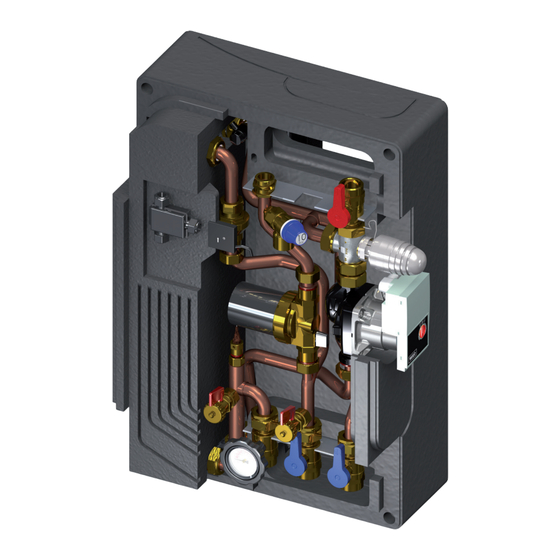
- Page 3 Installazione, uso e manutenzione 1. Introduzione del modulo T_FAST-I 20 Componenti principali Circolatore Wilo YONOS PARA 15/1-6 (alternativa con Wilo RS 15/6-3 KU) Valvola a sfera DN 20 1”M - ¾" F Maniglia rossa Maniglia blu Maniglia nera con termometro rosso Valvola di non ritorno Valvola a tre vie miscelatrice con attuatore termostatico 35 - 65°C Valvola di sfiato aria manuale da 3/8"...
-
Page 4: Componenti Principali
Installazione, uso e manutenzione 1. Introduzione del modulo T_FAST-I 35 Componenti principali Circolatore Wilo YONOS PARA 15/1-6 (alternativa con Wilo RS 15/6-3 KU) Valvola a sfera DN 20 1”M - ¾" F Maniglia rossa Maniglia blu Maniglia nera con termometro rosso Valvola di non ritorno Valvola a tre vie miscelatrice con attuatore termostatico 35 - 65°C Valvola di sfiato aria manuale da 3/8"... -
Page 5: Avvertenze Generali
Gentile Cliente, desideriamo ringraziarLa per aver scelto un prodotto Lovato. Siamo certi che sapremo ricambiare la fiducia che ci è stata accordata con un prodotto che è il frutto di un costante lavoro di ricerca e di una produzione sempre attenta ed orientata alla qualità. - Page 6 Installazione, uso e manutenzione 3. Installazione del modulo a muro ATTENZIONE! MANEGGIARE CON CURA! Estrarre dall’imballaggio il modulo e rimuovere il coperchio in EPP. IMPORTANTE! POSIZIONARE LA STAFFA IN MANIERA CORRETTA Allentare le 2 viti della dima di supporto (fig.2) e rimuoverla dalla parte posteriore del modulo per poi fissarla a parete con n.2 tasselli da 12 mm (non forniti) come indicato nel rif.
- Page 7 Installazione, uso e manutenzione 3. Installazione del modulo su puffer ATTENZIONE! MANEGGIARE CON CURA! Estrarre dall’imballaggio il modulo e rimuovere il coperchio in EPP. ATTENZIONE! L’INTERASSE DEI FORI VA PREVENTIVA- MENTE COMUNICATO AL PRODUTTORE DEL BOILER IN FASE D’ORDINE (SERVIRSI DLLE DISTANZE NELLA FIGuRA 3) Allentare le 2 viti della dima di supporto (fig.2) e rimuoverla dalla parte posteriore del modulo.
- Page 8 Installazione, uso e manutenzione 4. Connessione idraulica UNITA’ DI vALORI LIMITE PER SCAMBIATORI COMPONENTI MISuRA CON SALDATuRA IN RAME IMPORTANTE 7-9 (considerato indice di saturazione) Per gli impianti di produzione acqua calda sanitaria prevedere un filtro raccogli Indice di Saturazione(delta PH) -0.2<0<+0.2 impurità...
- Page 9 Installazione, uso e manutenzione 6. Dimensioni - Messa in funzione del modulo 1 - Riempire il circuito primario. 2 - Riempire il circuito secondario (sanitario) utilizzando gli appositi rubinetti di carico/scarico. 3 - Controllare la tenuta idraulica del modulo e sfiatare l’aria presente per un buon rendimento dell’impianto.
- Page 10 Installazione, uso e manutenzione 8. Lavaggio scambiatore (circuito secondario) - Intercettare il flusso chiudendo le valvole a sfera rif. 1a e 1b - Introdurre il fluido dal rubinetto rif. 2a - Far fuoriuscire il liquido dal rubinetto rif. 2b, lasciando fluire per il tempo necessario alla pulizia.
- Page 11 Module start-up - Circulation kit connections Washing of heat exchanger Picture and technical data are not binding. LOVATO Spa will reserve the right to bring change without obbligation of notice. It is forbidden reproduce copy, drawing or texties, partial or total without previous written authorization.
- Page 12 Assembling instructions and maintenance 1. T-FAST I 20 introduction Components: Pump type Wilo YONOS PARA 15/1-6 (alternativa con Wilo RS 15/6-3 KU) Ball valve DN 20 1”M - ¾" F Red handle Blue handle Black handle with red thermometer Check valve 3-way mixing thermostatic valve 35 - 65°C Manual air vent valve 3/8”...
- Page 13 Assembling instructions and maintenance 1. T-FAST I35 introduction Components Pump type Wilo YONOS PARA 15/1-6 (alternativa con Wilo RS 15/6-3 KU) Ball valve DN 20 1”M - ¾" F Red handle Blue handle Black handle with red thermometer Check valve 3-way mixing thermostatic valve 35 - 65°C Manual air vent valve 3/8”...
-
Page 14: General Warning
2. General indication Dear costumer, Thank you for choosing a Lovato product. We are confident that we will reciprocate the trust that has been granted to our product which is the result of our researches, work and sense for high quality. - Page 15 Assembling instructions and maintenance 3. Installation on the wall ATTENTION! HANDLE IT WITH CARE! Pull out the module from the package and remove the cover. IMPORTANT! PLACE THE BRACKET IN THE CORRECT PLACE Slacken the 2 screws of the support jig (pic.2) and remove it from the back part of the module.
- Page 16 Assembling instructions and maintenance 3. Installation on the puffer ATTENTION! HANDLE IT WITH CARE! Pull out the module from the package and remove the cover. ATTENTION! THE HOLES CENTER DISTANCE HAS TO BE TRANSMITTED TO THE BOILER’S MANUFAC- TURER WHEN PLACING THE ORDER (USE THE DISTANCE IN THE PICTuRE 3) Slacken the 2 screws of the support jig (pic.2) and remove it from the back part of the module.
- Page 17 Assembling instructions and maintenance 4. Hydraulic connections LIMIT vALuES FOR COPPER SOLDERED DESCRIPTION uNIT HEAT EXCHANGER IMPORTANT 7-9 (including saturation factor) Saturation factor(delta PH)) -0.2<0<+0.2 For installations of domestic hot water provide for a filter to protect the safety of the systems.
-
Page 18: Terminal Board
Assembling instructions and maintenance 6. Messa in funzione del modulo 6. Module start-up 65 65 1 - Fill the primary circuit. 2 - Fill the secondary circuit (hygenic water) through the load/unload caps. 3 - Check the hydraulic tight and venting the air. 4 - Powering the module. - Page 19 Assembling instructions and maintenance 8. Washing of heat exchanger (secondary circuit) 8. Plate exchanger flushing (secondary circuit) - Intercept the flow and close the ball valves ref. 1a and 1b - Intercept the flow and close the ball valves ref. 1a and 1b - Introduce the fluid from the valve ref.
- Page 20 Abwaschen des Tauschers Abbildungen und technische Daten sind nicht bindend. Die LOVATO SpA behält sich das Recht vor Änderungen, ohne Ankündigungen oder Mitteilungen vorzunehmen. Es ist verboten Dokumente, Zeichnungen oder Texte, teilweise oder vollständig ohne vorherige schriftliche Genehmigung, durch die LOVATO SpA, zu kopieren.
- Page 21 Montage - und Wartungsanleitung 1. Einführung des Moduls T_FAST-I 20 Bestandteile Pumpe Wilo YONOS PARA 15/1-6 (Alternative mit Wilo RS 15/6-3 KU) Kugelventil DN 20 1”M - ¾” F Handgriff Rot Handgriff Blau Handgriff Schwars mit rotem Thermometer Rückschlagventil 3-Wege-Mischerventil mit thermostatischem Antrieb 35 - 65°C Manuelles Auslassventil zu 3/8”...
- Page 22 Montage - und Wartungsanleitung 1. Einführung des Moduls T_FAST-I 35 Bestandteile Pumpe Wilo YONOS PARA 15/1-6 (Alternative zu Wilo RS 15/6-3 KU) Kugelventil DN 20 1”M - ¾” F Handgriff Rot Handgriff Blau Handgriff Schwars mit rotem Thermometer Rückschlagventil 3-Wege-Mischerventil mit thermostatischem Antrieb 35 - 65°C Manuelles Auslassventil zu 3/8”...
-
Page 23: Elektrischer Anschluss
2. Allgemeine Hinweise für den Endbediener Sehr geehrter Kunde, Vielen Dank, dass Sie sich für ein Lovato Produkt entschieden haben. Wir sind zuversichtlich, dass wir die Erwatungen, in unsere Produkte, welche das Ergebnis unserer Forschungen und unseres Streben nach Qualität sind, erfüllen werden. - Page 24 Montage - und Wartungsanleitung 3. Installations des Moduls an die Wand AChTuNG! MIT SORGFALT BEHANDELN! Das Modul aus der Verpackung entnehmen und die EPP-Abdeckung entfernen. WICHTIG! DIE HALTERUNG KORREKT POSIZIONIEREN . die zwei Schrauben der Halterungslehre losschrauben (Abb.2) und die Lehre von der hinteren Seite des Moduls entfernen. Die Lehre dann mit 2 Dübeln zu 12 mm (nicht inbegriffen) an die Wand gemäss Ref.
- Page 25 Montage - und Wartungsanleitung 3. Installation des Moduls an Puffer AChTuNG! MIT SORGFALT BEHANDELN! Das Modul aus der Verpackung entnehmen und die EPP-Abdeckung AChTuNG! DIE ZWISCHENACHSE DER BOHRUNGEN MUSS DEM HEIZKESSELHERSTELLER BEI DER BESTELLUNG MITGETEILT WERDEN (ES SOLLEN DIE ABSTÄNDE WIE IN ABB. 1A VERWENDET WERDEN) .
- Page 26 Montage - und Wartungsanleitung 4. Anschlüsse GRENZWERTE WÄRMETAUSCHER, KOMPONENTEN MASSEINhEIT KUPFER-SCHWEISSGELÖTET WICHTIG 7-9 (als Sättigungsindex betrachtet) Für die Anlagen zur Produktion von Frischwasser wird es empfohlen, die Sättigungsindex (des PH) -0.2<0<+0.2 Anlagen mit einem Filter für die Unreinigkeit des Wassers am Eingang Gesamthärte °Fr 15-30...
- Page 27 Montage - und Wartungsanleitung 6. Inbetribnahme des Moduls 1 – Primärklreislauf einfüllen. 2 – Sekundärkreislauf einfüllen, indem die entsprechenden Ein-/Auslasshähne verwendet. 3 – Hydraulische Dichtigkeit des Moduls kontrollieren und Luft auslassen. 4 – Modul einspeisen. 5 – Korrekte Funktionsweise des Kreislauf kontrollieren. TERMINAL BOARD CIRCOLATORE 7.
- Page 28 Montage - und Wartungsanleitung 8. Durchspülung des Plattenwärmetauschers - Unterbrechen Sie den Fluss indem Sie die Kugelhähne 1a und 1b schließen - Füllen Sie die Flüssigkeit über das Ventil 2a ein. - Spülen Sie mit der Flüssigkeit durch das Ventil 2b, für die notwendige Dauer des Durchspülungsvorgangs.
- Page 29 Lavage de l’échangeur Les illustrations et les données indiquées dans ce catalogne n’engagent pas la société. LOVATO SpA qui se réserve le droit d’apporter des modifications sans obligation de préavis. La reproduction partielle ou totale des plans, des textes ou des illustrations est interdite sans autorisation écrite.
-
Page 30: Composants Principaux
Instructions relatives à l’installation, l’utilisation et la maintenance 1. Présentation du module T_FAST-I20 Composants principaux Pompe de circulation Wilo YONOS PARA 15/1-6 (en alternative avec Wilo RS 15/6-3 KU) Vanne à bille DN 20 1”M - ¾” F Poignée rouge Poignée bleue Poignée noire avec thermomètre rouge Vanne de non retour... - Page 31 Instructions relatives à l’installation, l’utilisation et la maintenance 1. Présentation du module T_FAST-I35 Composants principaux Pompe de circulation Wilo YONOS PARA 15/1-6 (en alternative avec Wilo RS 15/6-3 KU) Vanne à bille DN 20 1”M - ¾” F Poignée rouge Poignée bleue Poignée noire avec thermomètre rouge Vanne de non retour...
-
Page 32: Controles Preliminaires
Cher Client, nous désirons vous remercier pour avoir choisi un produit de la société Lovato. Nous sommes certains de mériter la confiance que vous nous avez accordée grâce à un produit qui est le fruit d’un travail constant de recherche et d’une production orientée et très attentive à la qualité. - Page 33 Instructions relatives à l’installation, l’utilisation et la maintenance 3. Installation murale ATTENTION ! MANIPULER EN FAISANT ATTENTION! Extraire de l’emballage le module et enlever le couvercle en EPP. IMPORTANT! POSITIONNER LE SUPPORT DE FACON CORRECTE Desserrer les 2 vis de la tige de prédisposition (fig.2) et enlever cette dernière de la partie arrière du module puis, veuillez la fixer sur le mur au moyen de 2 chevilles de 12 mm (non fournies) comme indiqué...
- Page 34 Instructions relatives à l’installation, l’utilisation et la maintenance 3. Installation sur ballon tampon ATTENTION ! MANIPULER EN FAISANT ATTENTION! Extraire de l’emballage le module et enlever le couvercle en EPP. ATTENTION! L’INTERAXE DES TROUS DOIT ETRE PREA- LABLEMENT COMMUNIQUE AU FABRICANT DU BALLON LORS DE LA PASSATION DE LA COMMANDE (VEUILLEZ UTILISER LES DISTANCES INDIQUEES SUR LA FIGuRE 1A).
- Page 35 Instructions relatives à l’installation, l’utilisation et la maintenance 4. Anschlüsse uNITE DE vALEuRS LIMITES POuR LES EChAN- COMPONSANTS MESuRE GEuRS AvEC SOuDAGE EN CuIvRE IMPORTANT 7-9 (considéré index de saturation) Index de Saturation delta PH) -0.2<0<+0.2 Pour les équipements de production d’eau chaude sanitaire prévoir un filtre de récupération des impuretés pour la protection de l’équipement même.
- Page 36 Instructions relatives à l’installation, l’utilisation et la maintenance 6. Mise en service du module 1 – Remplir le circuit primaire. 2 – Remplir le circuit secondaire (eau chaude sanitaire) en utilisant les robi nets spécifiques de remplissage et de vidange. 3 –...
- Page 37 Instructions relatives à l’installation, l’utilisation et la maintenance 8. Lavage de l’echangeur de chaleur - Arrêter le flux en fermant les vannes à boisseau sphérique réf. 1a et 1b - Introduire le flux par le robinet réf. 2a - Faire sortir le liquide par le robinet réf. 2b, laissant l’écoule- ment pendant le temps nécessaire pour le nettoyage.
- Page 39 L’auteur de ce manuel décline donc toute responsabilité pour les erreurs, inexactitudes ou omissions ainsi que pour les dommages, réclamations ou pertes pouvant en résulter. Sous réserve de modifications ou améliorations techniques. LOVATO S.p.A. Via Selva, 4/a - 37040 Gazzolo d’Arcole VR - ITALIA Tel.
Need help?
Do you have a question about the T FAST-I 20 and is the answer not in the manual?
Questions and answers