Table of Contents
Advertisement
Available languages
Available languages
Quick Links
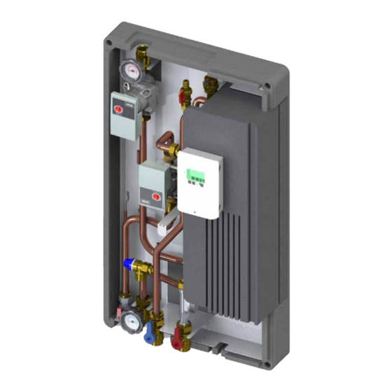
T-FAST ie40
Modulo di produzione ACS
DHW production modules
Frischwasserstationen
Modules de production ECS
Istruzioni per l'installazione, l'uso e la manutenzione
Assembling instructions and maintenance
Montage - und Wartungsanleitung
Instructions relatives à l'installation, l'utilisation et la maintenance
Advertisement
Table of Contents

Related Manuals for Lovato T-FAST ie40


Summary of Contents for Lovato T-FAST ie40
- Page 1 T-FAST ie40 Modulo di produzione ACS DHW production modules Frischwasserstationen Modules de production ECS Istruzioni per l’installazione, l’uso e la manutenzione Assembling instructions and maintenance Montage - und Wartungsanleitung Instructions relatives à l’installation, l’utilisation et la maintenance...
- Page 2 SEZIONE 8: TABELLA PARAMETRI REGOLATORE SEZIONE 9: COMPONENTI Illustrazioni e dati presenti si intendono non impegnativi. LOVATO Spa si riserva il diritto di apportare modifiche senza obbligo di preavviso. È vietata la riproduzione parziale o totale di disegni, testi o illustrazioni senza autorizzazione scritta.
- Page 3 La LOVATO S.p.A. non è responsabile del prodotto modificato senza autorizzazione e tanto meno per l’uso di ricambi non originali.
- Page 4 Installazione, uso e manutenzione SEZIONE 2: DATI TECNICI COMPONENTI PRINCIPALI Circolatore primario ad alta efficienza Wilo YONOS PARA 15/1-7 Dima telaio verniciata nera Maniglia nera con termometro rosso (circuito primario) Valvola sfera DN20 M-F 1”- ¾” con valvola di ritegno e calotta Scambiatore di calore a piastre inox saldobrasate con isolamento Valvola di sicurezza 10 bar lato secondario (circuito sanitario) F-F ½”...
- Page 5 Installazione, uso e manutenzione CURVE CARATTERISTICHE CIRCOLATORE CIRCUITO PRIMARIO CIRCOLATORE AD ALTA EFFICIENZA WILO YONOS PARA 15/1-7 Per maggiori informazioni sul circolatore consultare il manuale Wilo all’interno dell’imballo. SCHEMA IDRAULICO 1 Circolatore primario ad alta efficienza 6 Kit ricircolo 2 Scambiatore a piastre 7 Vortex flow sensor 3 Pozzetto per sonda 8 Valvola a sfera DN20 con termometro...
- Page 6 Installazione, uso e manutenzione SEZIONE 3: DIMENSIONI E CONNESSIONI ¾” F 1”M Mandata primario Fig.2 F 3/4” Fig.1 Fig.2 Fig.1 M-F 1-¾” Uscita ACS Ingresso AFS Ingresso ricircolo Ritorno primario ¾” M ¾” F ¾” F ¾” F 1”M 1”M 1”M UNITA’...
- Page 7 Installazione, uso e manutenzione SEZIONE 4: ESEMPIO DI APPLICAZIONE Accumulo tecnico (puffer) Fonte di calore T-FAST ie 40 Uscita ACS Ricircolo Fonte di calore ausiliaria Rete SEZIONE 5: INSTALLAZIONE CONTROLLI PRELIMINARI Prima di ogni operazione rimuovere con cura l’imballo e controllare la perfetta integrità dell’apparecchiatura. Nel caso si evidenziassero dei difetti o dei danni non installare o cercare di riparare l’apparecchiatura ma rivolgersi al venditore.
- Page 8 Installazione, uso e manutenzione ATTENZIONE! MANEGGIARE CON CURA! Estrarre con cura il modulo dall’imballaggio facendo attenzione a non danneggiarlo e rimuovere il coperchio in EPP. N.B. TASSELLI ESCLUSI DALLA 2a 2a FORNITURA IMPORTANTE! POSIZIONARE IL MODULO IN MANIERA CORRETTA Fissare a muro n.3 tasselli da 12 mm (fig.2), rispettando le distanze come da rif.
- Page 9 Installazione, uso e manutenzione SEZIONE 6: MESSA IN FUNZIONE 1 - Aprire le valvole a sfera (A e B), riempire il circuito primario e sfiatare l’aria presente attraverso la valvola sfiato (C). 2 - Riempire il circuito secondario (sanitario) utilizzando gli appositi rubinetti di carico/scarico (1 e 2).
- Page 10 Installazione, uso e manutenzione INSTALLAZIONE E MESSA IN FUNZIONE KIT RICIRCOLO Circolatore Wilo YONOS PARA 15/7 PWM2 Valvola di ritegno Alloggiamento sonda ricircolo S2 Rubinetto di intercettazione PERICOLO! APPARECCHIO IN TENSIONE - Intercettare il flusso chiudendo le valvola a sfera “ingresso AFS” rif. 1 e uscita “ACS”...
- Page 11 Installazione, uso e manutenzione SEZIONE 7: COLLEGAMENTO ELETTRICO COLLEGAMENTO ELETTRICO MODULO CON REGOLATORE DIGITALE MFWC E CIRCOLATORI A VELOCITA’ VARIABILE Lato sonde Linee in tensione 230VAC 50-60Hz max. 12 V Connessione nella parte destra Attenzione della morsettiera! Pericolo Lato linee 230 VAC Bassa tensione max.
- Page 12 Installazione, uso e manutenzione SEZIONE 8: TABELLA PARAMETRI REGOLATORE Descrizione menù Descrizione Range impostazioni Default T-FAST ie 40 Impost. Utente 4. IMPOSTAZIONI T set point 30°C ÷ 90°C 45°C T max. 50°C ÷ 95°C 60°C 1÷12 / 1÷20 / 2÷40 / Tipo VFS 2 ÷...
- Page 13 Installazione, uso e manutenzione Descrizione menù Descrizione Range impostazioni Default T-FAST ie 40 Impost. Utente Richiesta / orari / richiesta+orari 6.8.1.2 Ricircolo Orari / sempre acceso Controllo pressione ON / OFF Off / 0÷0,6 bar / 0÷1 bar / 0÷1,6 6.9.2 RPS1/RPS2 bar / 0÷2,5 bar / 0÷4 bar / 0÷6...
- Page 14 Installazione, uso e manutenzione SEZIONE 9: COMPONENTI Misuratore di portata / temperatura VORTEX FLOWSENSOR (VFS) 2 - 40 l/min Vortex Flowsensor è un misuratore combinato di portata / temperatura concepito per la produzione di elevati volumi di acqua. E‘ realizzato in materiale composito, mentre l‘elemento sensibile è a base siliconica realiz- zato con tecnologia MEMS.
- Page 15 Installazione, uso e manutenzione...
- Page 16 SECTION 8: DIGITAL CONTROLLER INITIAL SETTINGS SECTION 9: COMPONENTS Picture and technical data are not binding. LOVATO Spa will reserve the right to bring change without obbligation of notice. It is forbidden reproduce copy, drawing or texties, partial or total without previous written authorization.
- Page 17 DESCRIPTION T-FAST ie40 is an instantaneous domestic hot water production module that uses the working principle of a stainless steel plates exchanger. The setting of the domestic hot water outlet temperature (secondary side) happens with the modulation of the primary circuit flow rate through a variable flow pump controlled by MFWC controller (PWM control).
- Page 18 Assembling instrunctions and maintenance SECTION 2: TECHNICAL DATA COMPONENTS High efficiency pump type Wilo YONOS PARA 15/1-7 Black template frame Black handle with red thermometer (primary circuit) Ball valve DN25 with 1”½ nut and check valve Brazed plate iron steel heat exchanger with insulation 10 bar safety valve secondary side (domestic water) F-F ½”...
- Page 19 Assembling instrunctions and maintenance PRIMARY CIRCUIT PUMP CHARACTERISTICS HIGH EFFICIENCY PUMP WILO YONOS PARA 15/1-7 For further informations about the pumps please read the Wilo manuals into the packaging HYDRAULIC CIRCUIT 1 Primary circuit high efficiency pump 6 Recirculation kit 2 Plate heat exchanger 7 Vortex flow sensor 3 Sensor pocket...
- Page 20 Assembling instrunctions and maintenance SECTION 3: DIMENSION AND CONNECTION ¾” F 1”M Primary supply Fig.2 F 3/4” Fig.1 Fig.2 Fig.1 M-F 1-¾” DHW outlet DCW inlet Recirculation inlet Primary return ¾” M ¾” F ¾” F ¾” F 1”M 1”M 1”M LIMIT VALUES FOR COPPER IMPORTANT...
- Page 21 Assembling instrunctions and maintenance SECTION 4: EXAMPLE OF USE Puffer Energy supplier T-FAST ie 40 DHW outlet Recirculation Energy supplier (optional) inlet SECTION 5: INSTALLATION PRELIMINARY CHECK Before every operation carefully remove the packaging and verify if there is external damages. In case of damages please do not install the products. Dispose the packaging parts in compliance with the local regulations.
- Page 22 Assembling instrunctions and maintenance ATTENTION! HANDLE IT WITH CARE! Pull out the module from the package and remove the cover. 2a 2a IMPORTANT! PLACE THE BRACKET IN THE CORRECT PLACE Fix No. 3 plugs on the wall (picture 2) respecting the distance as shown in rif.
- Page 23 Assembling instrunctions and maintenance SECTION 6: INSTALLATION 1 - Open the ball valves (A e B), Fill the primary circuit and venting the air through the air vent (C). 2 - Fill the secondary circuit (hygenic water) through the load/ unload caps.
- Page 24 Assembling instrunctions and maintenance RECIRCULATION KIT CONNECTIONS AND START UP DANGER! POWERED DEVICE - Shut-off the flow closing the ball valves “DCW supply” ref. 1 and “DHW outlet” Pump type Wilo YONOS ref.2 PARA 15/7 PWM2 - Remove the cap (3/4”F ) to the T_Fast module as indicated in the pic.3. - Install the recirculation kit (ref.4) screwing watertight the nut.
- Page 25 Assembling instrunctions and maintenance SECTION 7: ELECTRICAL CONNECTION COLLEGAMENTO ELETTRICO MODULO CON REGOLATORE DIGITALE MFWC E CIRCOLATORI A VELOCITA’ VARIABILE Put into the digital controller Sensor side Main voltages 230VAC / 50-60Hz max. 12 V Connection on the right part of the terminal Attention board! Danger...
- Page 26 Assembling instrunctions and maintenance SECTION 8: ELECTRICAL REGULATOR INITIAL SETTINGS Menu description Description Settings range Default T-FAST ie40 User settings 4. SETTINGS Target temperature 30°C ÷ 90°C 45°C Max temperature 60°C 50°C ÷ 95°C 1÷12 / 1÷20 / 2÷40 / VFS type 5÷100 / 10÷200 / 200÷400...
- Page 27 Assembling instrunctions and maintenance Menu description Description Settings range Default T-FAST ie40 User settings Signal V2 6.8.1.1 Circulation ON/OFF Request / periods / 6.8.1.2 Circulation request+periods / contin. Orari operation Pressure monitor ON / OFF Off / 0÷0,6 bar / 0÷1 bar / 6.9.2...
- Page 28 Assembling instrunctions and maintenance SECTION 9: COMPONENTS Temperature/flow rate gauge VORTEX FLOWSENSOR (VFS) 2 - 40 l/min Vortex Flowsensor is a combined flow rate/temperature gauge projected for high volume water production. It is made of composite material, while the sensor is made of a silicone base realised with MEMS technology. The gauge is corrosion resistant.
- Page 29 Assembling instrunctions and maintenance...
-
Page 30: Table Of Contents
SECTION 9: COMPOSANTS Les illustrations et les données indiquées dans ce catalogne n’engagent pas la société. LOVATO SpA qui se réserve le droit d’apporter des modifications sans obligation de préavis. La reproduction partielle ou totale des plans, des textes ou des illustrations est interdite sans autorisation écrite. -
Page 31: Section 1: Introduction Et Informations Générales
La société LOVATO S.p.A. sauf autorisation ne s’assume aucune responsabilité en présence d’un produit modifié et ceci s’applique aussi lors de l’utilisation de pièces de rechange non originales. -
Page 32: Section 2: Donnèes Techniques
Instructions relatives à l’installation, l’utilisation et la maintenance SECTION 2: DONNèES TECHNIqUES COMPOSANTS PRINCIPAUX Circolateur primaire Wilo YONOS PARA 15/1-7 Dima telaio verniciata nera Poigéee noir avec thermomètre rouge (circuit primaire) Valvola sfera DN20 M-F 1”- ¾” avec vanne de non retour et ecrou Echangeur de chaleur à... -
Page 33: Courbes Des Performances Circulateur Primaire
Instructions relatives à l’installation, l’utilisation et la maintenance COURBES DES PERFORMANCES CIRCULATEUR PRIMAIRE POMPE DE CIRCULATION WILO YONOS PARA 15/1-7 CIRCUIT HYDRAULIQUE 1 Circulateur primaire 6 Kit de recirculation 7 Vortex flow sensor Echangeur de chaleur 3 Gaine de capteur 8 Vanne à... -
Page 34: Section 3: Dimensions Et Connexions
Les matériaux de construction du module de production eau chaude sanitaire Ammoniac mg/l <2 modèle T-FAST ie40 respectent la réglementation objet de l’arrêté ministériel Hydrogène mg/l <300 174/2004, et ce conformément à la Directive 98/83/CE. -
Page 35: Section4: Exemple D'application
Instructions relatives à l’installation, l’utilisation et la maintenance SECTION4: EXEMPLE D’APPLICATION Ballon tampon énergie thermique T-FAST ie 40 Sortie ECS Recirculation énergie thermique auxiliaire Réseau SECTION 5: INSTALLATION CONTROLES PRELIMINAIRES Avant toute opération, veuillez enlever délicatement l’emballage et contrôler l’intégrité parfaite de l’appareillage. Dans le cas où vous constateriez des défauts ou des dommages, veuillez-vous adresser au revendeur et surtout veuillez ne pas installer ou tenter de réparer l’appareillage. - Page 36 Instructions relatives à l’installation, l’utilisation et la maintenance ATTENTION! MANIPULER EN FAISANT ATTENTION! Extraire de l’emballage le module et enlever le couvercle en EPP. N.B. LES CHEVILLES SONT 2a 2a EXCLUES DE LA FOURNITURE. IMPORTANT! POSITIONNER LE SUPPORT DE FACON CORRECTE Fixer sur le mur n.3 vis de 12 mm (fig.2) et respecter les distances comme représenté...
-
Page 37: Section 6: Mise En Service
Instructions relatives à l’installation, l’utilisation et la maintenance SECTION 6: MISE EN SERVICE 1 - Ouvrir le robinet à boisseau sphérique (A e B), remplir le circuit primaire en éliminant complètement l’air présent dans le circuit à travers les vannes de purge (C). 2 - Remplir le circuit secondaire (sanitaire) en utilisant les robinets appropriés d’alimentation / de vidange. -
Page 38: Installation Et Mise En Service Kit De Recirculation
Instructions relatives à l’installation, l’utilisation et la maintenance INSTALLATION ET MISE EN SERVICE KIT DE RECIRCULATION DANGER ! APPAREIL SOUS TENSION - Arrêter le flux en fermant les vannes à boisseau sphérique “entrée EFS” réf. 1 Circolateur Wilo YONOS et sortie “ECS” réf.2 PARA 15/7 PWM2 - Retirer le bouchon de ¾”... -
Page 39: Section 7: Branchement Électrique Mfwc
Instructions relatives à l’installation, l’utilisation et la maintenance SECTION 7: BRANCHEMENT ÉLECTRIqUE MFWC Connecter à le régulateur électronique Côté capteur Tensions réseau 230VAC 50-60Hz 12 V max Connection dans le terminal de Attention droite! Danger Côté secteur 230 VCA Basses tension 12VAC/DC max. Connection dans le terminal de gauche! -
Page 40: Section 8: Tableau Des Paramètres De La Centrale Mfwc
Instructions relatives à l’installation, l’utilisation et la maintenance SECTION 8: TABLEAU DES PARAMèTRES DE LA CENTRALE MFWC Description menu Description Paramètres Défaut T-FAST ie40 Paramètres utilisateur 4. PARAMÈTRES T cons 30°C ÷ 90°C 45°C T max. 50°C ÷ 95°C 60°C 1÷12 / 1÷20 / 2÷40 /... - Page 41 Instructions relatives à l’installation, l’utilisation et la maintenance Description menu Description Paramètres Défaut T-FAST ie40 Paramètres utilisateur Signal V2 6.8.1.1 Circulation marche/arrêt arrêt Demande / temps / Dem.+temps 6.8.1.2 Circulation Temps / Marche continue Controllo pressione ON / OFF Off / 0÷0,6 bar / 0÷1 bar / 0÷1,6 6.9.2...
- Page 42 Instructions relatives à l’installation, l’utilisation et la maintenance SEZIONE 9: COMPOSANTS Indicateur de température / débit VORTEX FLOWSENSOR (VFS) 2 - 40 l / min Vortex Flowsensor est une jauge de débit / température combinée projetée pour la production d’eau à grand volume.
- Page 43 Instructions relatives à l’installation, l’utilisation et la maintenance...
- Page 44 ABSCHNITT 8: MFWC ELEKTRONISCHE EINSTELLUNG ABSCHNITT 9: KOMPONENTE Abbildungen und technische Daten sind nicht bindend. Die LOVATO SpA behält sich das Recht vor Änderungen, ohne Ankündigungen oder Mitteilungen vorzunehmen. Es ist verboten Dokumente, Zeichnungen oder Texte, teilweise oder vollständig ohne vorherige schriftliche...
- Page 45 Anlage übernehmen.. Die LOVATO SpA ist nicht für das Produkt verantwortlich, wenn unerlaubte Veränderungen vorgenommen wurden oder Originalkomponentendurch Fremdteile ersetzt wurden. Ohne schriftliche Genehmigung des Herstellers ist es nicht gestattet, Veränderungen, An- und Umbauten amGerät vorzunehmen. Es ist zudem nicht gestattet, Zusatzkomponenten einzubauen, welche nicht zusammen mit dem Gerät geprüft worden sind.
- Page 46 Montage - und Wartungsanleitung ABSCHNITT 2: TECHNISCHE DATEN BESTANDTEILE Pumpe Primär Wilo YONOS PARA 15/1-7 Schwarz-lackierte Rahmenlehre Handgriff Schwars mit rotem Thermometer (Primärkreis) Messingkugelventil DN20 M-F 1”- ¾” mit Rücklaufventil und Überwurfmutter Inoxplatten-Wärmeaustauscher mit Isolierung Sicherheitsventil 10 bar sekundärkreis (circuito sanitario) F-F ½”...
- Page 47 Montage - und Wartungsanleitung LEISTUNGSDIAGRAMM PUMPE PRIMäRKREIS PUMPE WILO YONOS PARA 15/1-7 Für weitere Informationen zu den Pumpen bitte das Wilo-Handbuch in der Verpackung nachsehen. HYDRAULIKKREIS 1 Hocheffizienzpumpe 6 Zirkulationseinheit 2 Plattenwärmetauscher 7 Vortex flow sensor 3 Fühlerhalterung 8 Messingkugelventil DN20 mit Thermometer 4 Ein-/Auslasshahn Valvola di sicurezza Valvola sfiato aria...
- Page 48 Montage - und Wartungsanleitung ABSCHNITT 3: ABMESSUNGEN UND ANSCHLÜSSE ¾” F 1”M Vorlauf Primär Fig.2 F 3/4” Fig.1 Fig.2 Fig.1 M-F 1-¾” Ausgang Warmwasser Kaltwasser einlass Warmwasser auslass Rücklauf Primär ¾” M ¾” F ¾” F ¾” F 1”M 1”M 1”M MAS- GRENZWERTE WÄRMETAUSCHER,...
- Page 49 Montage - und Wartungsanleitung ABSCHNITT 4: ANWENDUNGSBEISPIEL Accumulo tecnico (puffer) Thermische Energie 1 T-FAST ie 40 Uscita ACS Warmwasser Thermische auslass Energie 2 Kaltwasser einlass ABSCHNITT 5: INSTALLATION VORPRÜFUNGEN Vor jeder Arbeit ist die Verpackung sorgfältig zu entfernen und der Gerätezustand zu überprüfen. Bei Feststellung von Fehlern oder Schäden nicht instal- lieren oder versuchen zu reparieren.
- Page 50 Montage - und Wartungsanleitung ACHTUNG! MIT SORGFALT BEHANDELN! Das Modul aus der Verpackung entnehmen und die EPP-Abdeckung entfernen. ANMERKUNG: DÜBEL IM LIEFE- 2a 2a RUMFANG NICHT ENTHALTEN WICHTIG! DIE HALTERUNG KORREKT POSIZIONIEREN Dübel zu 12 mm (Abb.2) an die Wand befestigen, Freiraum einhal- ten gemäß...
- Page 51 Montage - und Wartungsanleitung ABSCHNITT 6: INBETRIBNAHME DES MODULS 1 - Ventile aufmachen (A e B), Primärklreislauf einfüllen und Luft auslassen. 2 - Sekundärkreislauf einfüllen, indem die entsprechenden Ein-/ Auslasshähne verwendet. (1 e 2). 3 - Hydraulische Dichtigkeit des Moduls kontrollieren. 4 - Modul einspeisen.
- Page 52 Montage - und Wartungsanleitung INSTALLATION UND INBETRIEBNAHME ZIRKULATIONSSET Pumpe Wilo YONOS PARA Z 15/7 PWM2 FSM Rückschlagventil Positionierung (Halterung) Zirkulationsfühlre S2 Absperrventil ACHTUNG! NETZSPANNUNGEN - Durchfluss durch Schließen des Kugelhahns “Eingabe Frischwasser” Ref. 1 und Ausgang “Warmwasser” Ref. 2 festhalten - die Kappe ¾...
- Page 53 Montage - und Wartungsanleitung ABSCHNITT 7: ELEKTRISCHE VERBINDUNG COLLEGAMENTO ELETTRICO MODULO CON REGOLATORE DIGITALE MFWC E CIRCOLATORI A VELOCITA’ VARIABILE Collegare alla centralina Sensorseite Netzspannungen max. 12 V 230VAC 50-60 Hz Acthung Anschluss im rechten Klemmraum! Gefahr Netzseite 230 VAC Kleinspannungen max.
- Page 54 Montage - und Wartungsanleitung ABSCHNITT 8: ELEKTRONISCHE EINSTELLUNG Menübeschreibung Beschreibung Beschreibung Default T-FAST ie 40 Anwender-Einstellungen 4. EINSTELLUNGEN Tsoll 30°C ÷ 90°C 45°C T max. 50°C ÷ 95°C 60°C 1÷12 / 1÷20 / 2÷40 / VFS-Typ 2 ÷ 40 l/min 5÷100 / 10÷200 / 200÷400 l/min Zirkulation on / off...
- Page 55 Montage - und Wartungsanleitung Menübeschreibung Beschreibung Beschreibung Default T-FAST ie 40 Anwender-Einstellungen Anforderung / Zeit / Anf+Zeit / 6.8.1.2 Zirkulation Orari Dauerbetrieb Drucküberwachung ON / OFF Off / 0÷0,6 bar / 0÷1 bar / 0÷1,6 6.9.2 RPS Typ bar / 0÷2,5 bar / 0÷4 bar / 0÷6 bar / 0÷10 bar 6.14 Sommerzeit...
- Page 56 Montage - und Wartungsanleitung ABSCHNITT 9: KOMPONENTE Durchfluss-/ Temperaturmesser Vortex Flowsensor (VFS) 2 - 40 l/min Vortex Flowsensor ist ein kombiniertes Messgerät Strömung / Temperatur für die Herstellung von großen Wassermengen konzipiert. Es ist aus Verbundmaterial hergestellt, wobei das empfindliche Element mit silizium-basierten MEMS-Technologie hergestellt ist.
- Page 57 Montage - und Wartungsanleitung...
- Page 58 Smart Energy Solutions www.lovatospa.com LOVATO S.p.A. Via Selva, 4/a +39 045 618 2012 mail 37040 Gazzolo d’Arcole info@lovatospa.com lovatospa fax+39 045 618 2017 VERONA - ITALY...
Need help?
Do you have a question about the T-FAST ie40 and is the answer not in the manual?
Questions and answers