Table of Contents
Advertisement
Quick Links
Advertisement
Table of Contents

Related Manuals for Projoy Electric PEFS-PL Series


Summary of Contents for Projoy Electric PEFS-PL Series
-
Page 2: Safety Instructions
Installation Guide DISCLAIMER PROJOY assumes no responsibility for any loss, in particular for circuit damage, resulting from any violation of the specifications recommended and referred to in this specification. PROJOY assumes no responsibility for the damage of the product caused by the maintenance, improper use, wrong installation or wrong system design of the product by non-designated personnel. -
Page 3: Installation And Connection
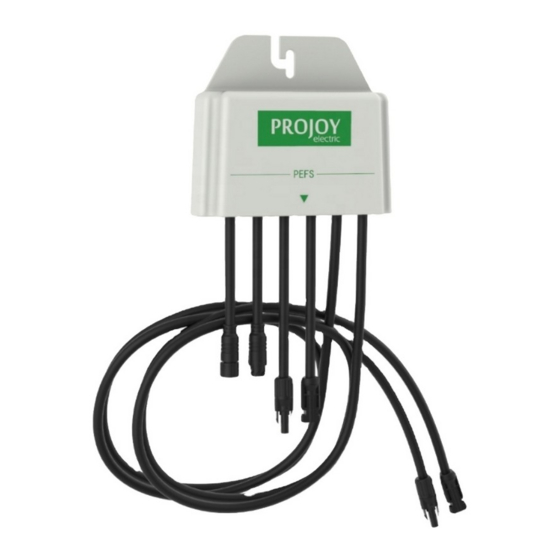
Installation Guide PARTS PEFS-PL PEFS unit - suitable for connecting two solar panels PEFS -ESW Emergency Rapid Shutdown Switch Unit (excludes 24 VDC power supply) INSTALLATION & CONNECTION One PEFS-PL will control two solar panels and for compliance with 2017 NEC it should be mounted within the array boundary of the two panels, where the two panels are no greater than 1’... - Page 4 Installation Guide Connect the two PV panels in series (typical wiring example below). Connect the array Positive (+) output connector to the PEFS-PL Positive (+) input connector. Connect the array Negative (-) output connector to the PEFS-PL Negative (-) input connector. Connect the PEFS-PL’s two output cables to the DC isolator/Solar Inverter ensuring that the correct polarity is maintained throughout the electrical wiring.
-
Page 5: Multiple Installations
Installation Guide If the connection is to be made through the bottom of PEFS-ESW product, the cable shall be drilled at the bottom until the aperture reaches the cable diameter, and there shall be a sealing method to seal the cable with the hole drilled at the bottom to ensure that the pfS-ESW product seal can reach IP68. -
Page 6: Operation
Installation Guide Waterproof terminal - Insert the seal case to the AMP terminal and connect one end to a PEFS-PL DC output connector in the series installation. If only one PEFS-PL is used, this section still needs to be sealed over the AMP terminal to prevent leakage. OPERATION Upon correct mounting and connection of the PEFS-PL to the solar panels and the Emergency Shutdown Switch;... -
Page 7: Troubleshooting
Installation Guide Maximum System Voltage 1500V Supply Voltage 24VDC Ambient Operating Temperature -30° C ~ +85° C (Automatic shutdown over 85 ° C) Storage Temperature -30° C ~ +85° C IP Level IP68 Fire-proof Level UL94-V0 Humidity 0%~90% at 20℃ Connector Warranty 10 years... - Page 8 Installation Guide is 0V (LED OFF) Check mains ON Check mains fuse Check mains voltage between L & N marked power supply PEFS-ESW terminals failure Check 24VDC between + & - marked terminals Turn red actuator anti-clockwise to release PEFS-ESW switch activated button Check 24VDC between switch out terminal &...
- Page 9 Installation Guide...
Need help?
Do you have a question about the PEFS-PL Series and is the answer not in the manual?
Questions and answers