Table of Contents
Advertisement
Available languages
Available languages
Advertisement
Chapters
Table of Contents

Related Manuals for EMAK MZ2060


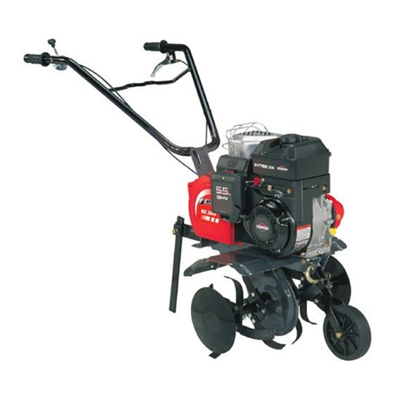
Summary of Contents for EMAK MZ2060
-
Page 3: Table Of Contents
ITALIANO INDICE DEL CONTENUTO - Sicurezza sul lavoro ---------------------- 2 - Informazioni e norme generali -------- 3 - Spiegazione dei simboli ---------------- 3 - Dati per l'identificazione ---------------- 3 - Dati tecnici --------------------------------- 3 - Rumore aereo e vibrazioni ------------ 3 - Descrizione dei comandi --------------- 4 - Montaggio della motozappa----------- 4 Montaggio del timone posteriore ----- 5... -
Page 4: Sicurezza Sul Lavoro
INFORMAZIONl ATTENZIONE - Pericolo di ustioni. RIGUARDANTI 10) Indossate abiti aderenti e calzature LA SICUREZZA di sicurezza antiscivolo completamente SUL LAVORO chiuse. 1) Leggete con attenzione il manuale 11) Controllate che tutti gli elementi di d’uso fino ad avere piena dimestichez- fissaggio siano ben stretti. -
Page 5: Informazionie Norme Generali
INFORMAZIONI E NORME GENERALI ARTI Dl RICAMBIO - Si consiglia vi- vamente di impiegare esclusivamente RICAMBI ORIGINALI. Le ordinazioni devono essere effettuate osservando le norme contenute nel Catalogo delle Parti di Ricambio. MANUTENZIONE DEL MOTORE - Le prescrizioni per l'uso e la manutenzio- fig.1 ne del motore sono contenute nel rispet- tivo libretto, copia del quale viene forni-... -
Page 6: Descrizione Dei Comandi
DESCRIZIONE DEI COMANDI (FIG. 2) 1) Manetta comando acceleratore a mano 2) Leva comando marcia di zappatura (dispositivo antinfortunistico). 3) Maniglia per avviamento a strappo (dispositivo autoavvolgente). 4) Timone per regolazione fresatura (registrabile). 5) Frese (con allargamento). 6) Carter protezione fresa. 7) Levacomando RM (dove prevista). -
Page 7: Montaggio Del Timone Posteriore
MONTAGGIO DEL TIMONE POSTERIORE (Fig. 4) - Posizionare il timone 3 in corrisponden- za del foro centrale, poi bloccare con l’apposita vite e dado autobloccante. Il timone può essere regolato in altez- - Svitare la vite 4, regolare e riavvitare (Fig.4). -
Page 8: Montaggio Delle Frese A Zappette
Fig. 6 Fig. 7 DISPOSITIVI DI SICUREZZA MONTAGGIO DELLE FRESE A ZAPPETTE (Fig. 6) Le macchine sono dotate di dispositivo 1. Pulire i mozzi delle frese e l’albero antinfortunistico, che causa il disinnesto porta-frese; spalmare una piccola quan- automatico della trasmissione del moto tità... -
Page 9: Avviamento Motore
AVVIAMENTO DEL MOTORE Per l’operazione di messa in moto fare riferimento al manuale Uso e Manuten- zione del motore. Note per il lavoro con la motozappa A motore avviato, appoggiare i coltelli sul terreno e tenendo saldamente la motozap-pa, infilare nel terreno il brac- cio del timone. -
Page 10: Manutenzione
MANUTENZIONE 1) Oliare periodicamente le articolazioni, i fili di comando, il perno supporto tendicinghia. 2) Mantenere la macchina e i coltelli re- lativamente puliti. 3) Verificare periodicamente almeno 1 volta ogni stagione i serraggi della bulloneria, principalmente quelli della fresa. Per il cambio olio e altre operazioni di manutenzione al motore (candele, filtro Fig. - Page 11 FRANÇAIS TABLE DES MATIERES securité travail..- Informations et normes générales ..11 - Explication des symboles .....11 - Données pour l’identification ....11 - Données techniques ......11 - Description des commandes ....12 - Bruit aérien et vibrations .......12 - Montage de la motobineuse ....
-
Page 12: La Securité Sur Le Travail
INFORMATIONS ATTENTION - Danger de brûlures. 10) Portez des vêtements adhérents et CONCERNANT des chaussures de sécurité anti- LA SECURITE dérapantes entièrement fermées. SUR LE TRAVAIL 11) Contrôlez que tous les éléments de 1) Lisez attentivement le manuel fixation sont bien serrés. d’utilisation afin d’avoir une totale 12) Retirez de la zone à... -
Page 13: Explication Des Symboles
GENERALITES PIECES DE RECHANGE - Il est vive- ment conseillé d'employer exclusive- ment des PIECES DE RECHANGE ORIGINALES. Les commandes doivent être effectuées selon les instructions contenues dans le Catalogue des Pièces de Rechange. ENTRETIEN DU MOTEUR - Les pre- scriptions pour l'emploi et l'entretien du fig.1 moteur sont contenues dans ce manuel,... -
Page 14: Montage De La Motobineuse
VIBRATIONS AUX MANCHERONS Relevé avec pondération selon ISO Ÿ 5349: 5,34 m/s DESCRIPTIONS DES COMMANDES (Fig. 2) 1) Manette commande accélérateur manuel. 2) Levier de commande vitesse de bi- nage (dispositif de sécurité). 3)Poignée pour démarrage par lanceur(dispositif à retour automatique) 4) Timon pour réglage fraisage (réglable). -
Page 15: Montage Du Timon Postérieur
MONTAGE DU TIMON POSTERIEUR (Fig. 4) - Positionner le timon 3 devant le trou central, bloquer ensuite avec la vis et l’écrou . Le timon peut être réglé en hau- teur. - Dévisser la vis 4, régler et revisser (Fig. 4). MONTAGE MANCHERONS Fig. -
Page 16: Montage Des Fraises À Dents
Fig. 6 Fig. 7 MONTAGE DES FRAISES DISPOSITIFS DE SECURITE A DENTS (Fig. 6) Les machines possèdent un dispositif de 1. Nettoyer les moyeux des fraises et sécurité, qui bloque automatiquement la l’arbre porte-fraise; mettre une petite transmission du mouvement à la fraise quantité... -
Page 17: Entretien
DEMARRAGE DU MOTEUR ENTRETIEN Pour mettre le moteur en route suivre les 1) Huiler périodiquement les articula- instructions du manuel Utilisation et en- tions, les fils de commande, le pivot sup- tretien du moteur. port du tendeur de courroie. Notes pour le travail avec la motobineuse 2) Conserver la machine et les coute- Lorsque le moteur est en marche, appuyer aux propres. -
Page 18: Recommandations Importantes
RECOMMANDATIONS IMPORTANTES 1. Après le montage des courroies, con- trôler qu’elles se trouvent à l’intérieur des tétons 1 (Fig. 9). 2. Pour éviter des dommages irrépara- bles à la courroie de la marche arrière, régler le fil de commande, de façon que le diamètre externe du tendeur de la courroie 2 affleure sur le profil externe de la paroi 3 (Fig. - Page 19 ENGLISH CONTENTS - Safety at works ........... 1 8 - Information and general rules ......1 9 - Explanation of symbols ........1 9 - Identification data ..........1 9 - Technical characteristics ........1 9 - Description of the controls ........2 0 - Airborne noise and vibration .......
-
Page 20: Safety At Works
INFORMATION tightened. CONCERNING 12) Remove stones, wires, glass, big SAFETY branches, metal and debris from the AT WORK area you want to till. 13) Do not use the motorhoe if safety 1) Read this use manual carefully until devices are not proper. you’re familiar with the controls and use 14) If you bump an object during work, of the motorhoe. -
Page 21: Information And General Rules
INFORMATION AND GENERAL RULES SPARE PARTS - You are highly recom- mended to use only GENUINE SPARE PARTS. Orders must be made obser- ving the rules given in the Spare Parts Catalogue. ENGINE SERVICING - The regulations for using and servicing the engine are fig.1 given in the appropriate booklet, a copy of which is provided with each machine. -
Page 22: Description Of The Controls
DESCRIPTION OF THE CONTROLS (Fig. 2) 1) Hand throttle control lever. 2) Hoeing gear control lever (safety device). 3) Handle for manual start (recoil device). 4) Drawbar for tilling adjustment (adjustable). 5) Tiller (with widening). 6) Tiller protection plate. 7) Reverse gear control lever (where applicable). -
Page 23: Assembly Of The Rear Drawbar
ASSEMBLY OF THE REAR DRAWBAR (Fig. 4) - Position drawbar 3 in correspondence with the central hole, then lock it with the screw and the self-locking nut. The drawbar can be adjusted in height. - Unloosen screw 4, adjust and screw back on (Fig. -
Page 24: Assembly Of The Hoe Tiller
Fig. 6 Fig. 7 ASSEMBLY OF THE HOE TILLER SAFETY DEVICES Fig. 6) The machine is equipped with an acci- 1. Clean the tiller hubs and the tiller shaft, dent prevention device which automati- apply a small amount of grease; this will cally disengages the motion drive to the make assembly and future removal ope- hoe when the correspondent levers on... -
Page 25: Engine Start
ENGINE START-UP Refer to the engine’s Use and Mainte- nance handbook for starting. Notes on how to use the Motorhoe Once engine is running, place the tines on the ground and, whilst firmly keeping hold of the Motorhoe, insert the draw arm into the soil. -
Page 26: Maintenance
MAINTENANCE 1) Periodically oil joints, control wires and the belt-tightener support pin. 2) Keep the machine and knifes clean. 3) Periodically, at least once a season, check the tightness of nuts and bolts, mainly those concerning the rotary hoe. To change the oil and service the engi- ne (spark plugs, air filter, adjustments) refer to the provided engine handbook. - Page 27 DEUTSCH HINHALTSVERZEICHNIS - Sichereit am Arbeitsplatz ........ 26 - Allgemeine Hinweise und Vorschriften ... 27 - Zeichenerklärung ..........27 - Identifizierungsdaten ........27 - Technische Daten ........... 27 - Beschreibung der Bedienungselemente ..28 - Geräuschpegel und Vibrationen ..... 28 - Montage der Motorhacke........
- Page 28 rutschfeste, komplett geschlossene BEDIENUNG Sicherheits-schuhe. 11) Überprüfen Sie, ob alle Befestigungs- INFORMATIONEN elemente gut angezogen sind. ZUR SICHERHEIT 12) Entfernen Sie von dem Feld, das bestellt AM ARBEITSPLATZ werden soll, alle Steine, Drähte, Glassplitter, Aste, Metallstücke und Geröllbrocken. 1) Lesen Sie dieses Handbuch aufmerksam 13) Verwenden Sie die Hackmaschine nicht, durch, bis Sie mit den Bedienungselemen wenn die Sicherheitsvorrichtungen nicht voll...
-
Page 29: Allgemeine Hinweise Und Vorschriften
ALLGEMEINE HINWEISE UND VORSCHRIFTEN ERSATZTEILE - Wir raten Ihnen in Ihrem eigenen Interesse nur ORIGI- NAL-ERSATZTEILE zu verwenden. Bei Bestellungen von Ersatzteilen beachten Sie bitte die im Ersatzteil-Katalog an- geführten Hinweise. MOTORENWARTUNG - Hinweise für Bedienung und Wartung des Motors sind in der entsprechenden Bedienun- fig.1 gsanleitung enthalten, die Ihnen bei... -
Page 30: Beschreibung Der Bedienungselemente
VIBRATIONEN AN DEN LENKHOLMEN Ÿ Gemessen nach ISO 5349: 5,34 m/s BESCHREIBUNG DER BEDIENUNGSELEMENTE (Abb. 2) 1) Manueller Gashebel 2) Bedienungshebel für das Hackgetrie- be (Unfallschutz- Sicherheitsvorri- chtung) 3) Anlasserzuggriff (Reversierstarter) 4) Deichsel für die Fräseinstellung (ver- stellbar) 5) Fräsen (mit Verbreiterung) 6) Frässchutzgehäuse 7) Rückwärtsganghebel (falls vorge- sehen) -
Page 31: Montage Der Hinteren Deichsel
MONTAGE DER HINTEREN DEICH- SEL (Abb. 4) -Stimmen Sie die Deichsel 3 auf das mit- tlere Loch ab, und stellen Sie sie mit der dafür vorgesehenen Schraube und der selbstsich-ernden Mutter fest. Die Dei- chsel ist höhenverstellbar. - Lockern Sie die Schraube 4, nehmen Sie die Einstellung vor, und befestigen Fig. -
Page 32: Montage Der Hackfräsen
Fig. 6 Fig. 7 richtung wird wie folgt vorgenommen: stets montiert werden müssen. Die Mon- - Wenn Sie den Hebel 4 ziehen7 wird tage der Schutzgehäuse entspricht ei- der Vorwärtsgang eingelegt. ner Unfallschutz-Vorschrift und muß - Wenn Sie den Hebel 5 ziehen, wird der deshalb unbedingt vor Inbetriebnahme Rückwärtsgang eingelegt (Abb. -
Page 33: Anlassen Des Motors
getriebe steuert, die Fräse erst in Gang Loch herauszufließen beginnen, kurz setzen, nachdem er ein Spiel von der bevor die Maschine (am Punkt A) den Hälfte der gesamten Zugmöglichkeit in Boden berührt. Anspruch genommen hat; wenn dieser d) Verschließen Sie das Loch mit dem Hebel ganz gezogen ist (Arbeitsstel- Schraubverschluß. -
Page 34: Wichtige Hinweise
sämtliche Bolzen, besonders diejenigen der Fräse, fest angezogen sind. Für den Ölwechsel und andere Moto- renwartungsarbeiten (Zündkerzen, Luf- tfilter, Einstellungen) schlagen Sie bitte im beigefügten Motoren- Handbuch nach. WICHTIGE HINWEISE 1. Nach der Montage der Riemen kon- trollieren, daß diese in die Sprossen 1 (Abb. - Page 35 ESPAÑOL INDICE DEL CONTENIDO - La seguridad .......... 34 - Informaciones y normas generales ..35 - Explicación de los símbolos ....35 - Datos para la identificación ....35 - Datos técnicos ........35 - Descripción de los mandos ....36 - Ruido aéreo y vibraciones ..... 36 - Montaje de la motoazada ......
-
Page 36: La Seguridad
INFORMACIONES 10) Lleven trajes adherentes y zapatos RELATIVAS A LA de seguridad anti-resbalón, totalmente SEGURIDAD cerradas. 1) Lean con cuidado el manual de uso 11) Controlen que todos los elementos para tener una confianza total con los de fjación estén bien cerrados mandos y la utilización de la motoazada. -
Page 37: Informacionesy Normas Generales
INFORMACIONES Y NORMAS GENERALES REPUESTOS - Se aconseja el empleo exclusivo de REPUESTOS ORIGINALES. Las órdenes de compra deben ser efec- tuadas observando las normas conteni- das en el Catálogo de los Repuestos. MANTENIMIENTO DEL MOTOR - Las indicaciones para la utilización y el man- tenimiento del motor se hallan en la cor- respondiente libreta de identificación, fig.1... -
Page 38: Descripción De Los Mandos
VIBRACIONES EN LAS MANCERAS Datos tomados con ponderación según Ÿ ISO 5349: 5,34 m/s DESCRIPCION DE LOS MANDOS (Fig. 2) 1) Manecilla mando acelerador de mano. 2) Palanca mando marcha de zapado (dispositivo anti infortunio) 3) Manecilla para el encendido a explosión (dispositivo reversible) 4) Timón para regulación fresado (regulable) -
Page 39: Montaje Del Timón Posterior
MONTAJE DEL TIMON POSTERIOR (Fig. 4) - Ubicar el timón 3 en correspondencia con el agujero central, luego bloquear con el tornillo y la tuerca de autobloqueo correspondientes. El timón puede ser regulado en altura. - Desatornillar los tornillos 4, regular y atornillar nuevamente (Fig. -
Page 40: Montaje De Las Fresas Con Azadas
Fig. 6 Fig. 7 MONTAJE DE LAS FRESAS CON lizando los tornillos de fijación. Verificar AZADAS (Fig. 6) que estén bien apretados antes del uso. 1. Limpiar los bujes de las fresas y el DISPOSITIVOS DE SEGURIDAD eje porta fresas; desparramar una pe- queña cantidad de grasa para facilitar Las máquinas están dotadas de dispo- el montaje y la futura remoción de las... -
Page 41: Mantenimiento
ENCENDIDO DEL MOTOR Si las regulaciones no son suficientes Para el encendido del motor, atenerse para obtener dichas condiciones (la re- a las indicaciones presentes en el ma- gulación ha llegado al fondo del filetea- nual de instrucciones de “Uso y Mante- do) proceder a regular la correa trape- nimiento”... -
Page 42: Advertencias Importantes
ADVERTENCIAS IMPORTANTES 1. Después del montaje de las correas, controlar que se encuentren en el inte- rior de las espigas 1 (Fig. 9). 2 - Para evitar daños irreparables en la correa de la marcha atrás, regular el cable de mando, para que el diámetro externo del extensor de correa 2 roce el perfil externo de la protección 3 (Fig. - Page 43 NEDERLANDES INHOUDSOPGAVE - De veiligheid op het werk ......... 4 2 - Ter informatie en algemene richtlijnen ..... 4 3 - Verklaring van de symbolen ......4 3 - Identificatiegegevens ........4 3 - Technische gegevens ........4 3 - Bedieningshendels ........... 4 4 - Geluidsproductie en trillingen ......
-
Page 44: De Veiligheid Op Het Werk
INFORMATIES bereiken. M.B.T. DE VEILIGHEID OPGELET – Verbrandingsgevaar OP HET WERK. 10) Draag strakke kleding en antislip Lees aandachtig de gebruiksaanwij- veiligheidsschoenen die volledig gesloten zingen tot u volkomen vertrouwd bent met zijn. de bedieningen en het gebruik van de 11) Controleer dat alle bevestigings- motorhakfrees. -
Page 45: Verklaring Van De Symbolen
TER INFORMATIE/ ALGEMENE RlCHTLIJNEN WISSELSTUKKEN - Het is in Uw eigen belang enkel AUTHENTIEKE WIS- SELSTUKKEN aan te wenden. Om wis- selstukken te bestellen dient U de richtlij- nen op te volgen zoals uiteengezet in de Wisselstukkencatalogus. ONDERHOUD VAN DE MOTOR - De instructies voor de bediening en het on- derhoud van de motor zijn vervat in een fig.1... - Page 46 TRILLINGEN OP DE STUURHENDELS Meting gewogen volgens ISO 5349: Ÿ 5,34 m/s BEDIENINGSHENDELS (Fig. 2) 1) Handbediening gashendel. 2) Bedieningshendel omspitversnelling (beveiliging tegen ongevallen). 3) Handvat repeteerstarter (repeteer- mechanisme). 4) Stuurstang voor afstelling frees (in- stelbaar). 5) Fresen (met verschillende breedtes). 6) Beschermkap frees.
-
Page 47: Monteren Van De Achterstuurstang
MONTEREN VAN DE ACHTERSTUURSTANG - Positioneer stuurstang (3) zodanig dat deze zich ter hoogte van het middelste gat bevindt, bevestig hem vervolgens met de daarvoor bestemde schroef en zelf-blokkerende moer. De stanghoogte is regelbaar. - Draai schroef 4 los, afstellen en weer vastzetten (Fig. -
Page 48: Monteren Van De Spitfresen
Fig. 6 Fig. 7 Hoe het trekken te bewerkstelligen pen (4) die altijd bevestigd dienen te zijn (vooruit achteruit): tijdens het werk. Het aanbrengen van - Hendel 4 aantrekken: vooruitversnelling de beschermingskappen betekent het - Hendel 5 aantrekken: achteruitversnel- naleven van de anti-ongevallenvoor- ling (Fig. -
Page 49: Starten Van De Motor
de machine in schuine stand gepositio- (Fig. 8 detail 2) en van de instelschroe- neerd te worden; de olie dient uit het gat ven van de bedieningshendels. Boven- te lopen net voordat de machine (met dien dient de hendel van de omspitver- punt A) de grond raakt. -
Page 50: Belangrijke Wenken
ral die van de frees. Voor wat betreft de olieverversing en andere onderhoudswerkzaamheden van de motor (bougies, luchtfilter, afstel- lingen) dient de handleiding van de mo- tor geraadpleegd te worden. BELANGRIJKE WENKEN 1. Na de aandrijfriemen gemonteerd te hebben dient gecontroleerd te worden dat ze langs de binnenkant van de pin- nen (1) lopen. - Page 51 PORTUGUÊS INDICE DO CONTEUDO - A seguranca durante o trabaho ......50 - Informação e normas gerais ......51 - Explicação dos símbolos ........51 - Dados para a identificação ....... 51 - Características técnicas ........51 - Descrição dos comandos ......... 52 - Ruído aéreo e vibrações ........
- Page 52 INFORMAÇÕES ATENÇÃO! perigo de queimaduras. SOBRE A SEGURANÇA 10) A roupa do operador tem que ser DURANTE apertada; evite de usar roupas largas e O TRABALHO use calçados de segurança com sola de borracha. 1) Leia este manual com atenção até 11) Certifique-se que todos os adquirir a completa familiaridade com os elementos de fixação estejam bem...
-
Page 53: Explicação Dos Símbolos
INFORMAÇÕES E NORMAS GERAIS PEÇAS ORIGINAIS - Aconselha-se vi- vamente a aplicação exclusivamente PEÇAS ORIGINAIS. As encomendas têm que ser feitas observando as nor- mas contidas no Catálogo de Peças. MANUTENÇAO DO MOTOR - As pre- scrições para o uso e a manutenção do motor estão contidas no respectivo ma- nual, cópia do qual vem fornecido em fig.1... -
Page 54: Descrição Dos Comandos
VIBRAÇÕES DOS BRAÇOS Relevamento com consideração segun- Ÿ do ISO 5349: 5,34 m/s DESCRIÇÃO DOS COMANDOS (Fig. 2) 1) Manete comando acelerador manual 2) Manete de comando marcha para enxadar (dispositivo de segurança) 3) Alavanca para o arranque manual (dispositivo reversível) 4) Timão para a regulação do trabalho de frese (registrável) 5) Fresa (com alargamento) -
Page 55: Montagem Do Timão Posterior
MONTAGEM DO TIMÃO POSTERIOR (Fig. 4) - Posicionar o timão 3 em corrispondên- cia com o buraco central, depois bloque- ar como parafuso apropriado e o dado autobloqueador. O timão pode ser re- gulado em altura. - Aliviar o parafuso 4, regular e apertar de novo (Fig. - Page 56 Fig. 6 Fig. 7 MONTAGEM DAS DISPOSITIVOS FRESAS A SACHO (Fig. 6) DE SEGURANÇA 1. Limpar os canhões das fresas e do A máquina está equipada com um di- eixo leva-fresas; untar com um pouco de spositivo de segurança que desliga au- massa para facilitar a montagem e re- tomáticamente a transmissão de mar- moção das fresas.
-
Page 57: Arranque Do Motor
ARRANQUE DO MOTOR a mola de carga da estira-correia tem que se alongar de cerca 6-8 mm. Se Para pôr em marcha o motor, consultar estes registros não forem suficientes a o manual de Uso e Manutenção do obter as ditas condições (o registro esti- motor. -
Page 58: Advertencias Importantes
ADVERTENCIAS IMPORTANTES 1. Depois de ter montado as correias, controlar que estas estejam no interno dos estacas 1 (Fig. 9). 2. Onde evitar desgastes irreparáveis à correia da marcha atrás, registrar o fio de comando de maneira que o diame- tro exterior da estira-correia 2 esflore o profíl exterior da antepara 3 (Fig. - Page 59 Polski SPIS ZAWARTOŚCI - Bezpieczeństwo przy pracy ........58 - Informacje i zasady ogólne ......... 59 - Objaśnienia symboli ..........59 - Dane identyfikacyjne ........... 59 - Dane techniczne ..........59 - Hałas powietrza i drgania ........59 - Opis elementów sterowniczych ......60 - Montaż...
- Page 60 11) Upewnić się, czy wszystkie ele- INFORMACJE DOTYCZĄCE menty mocujące sa dobrze dokręcone. BEZPIECZEŃSTWA PODCZAS 12) Usunąć z obszaru spulchniania wszys- PRACY tkie kamienie, druty, szkła, grube gałęzie, Uważnie przeczytać podręcznik złom i gruz. użytkowania dla uzyskania pełnej swobo- 13) Nie stosować kopaczki mechanicz- dy w obcowaniu z urządzeniami sterow- nej, jeśli jej zabezpieczenia nie są...
-
Page 61: Objaśnienia Symboli
INFORMACJE I NORMY OGÓLNE CZĘŚCI ZAMIENNE – Zaleca się gorąco stosowanie wyłącznie ORYGINALNYCH CZĘŚCI ZAMIENNYCH. - Zamówienia powinny być składane z zachowaniem zasad zawartych w katalogu części zamiennych. KONSERWACJA SILNIKA – Zalecenia dotyczące użytkowania oraz konserwacji silnika zawarte są w odpowiedniej broszur- ze, jej egzemplarz dostarczany jest wraz z ilustr każdą... - Page 62 OPIS ELEMENTÓW STROWNICZYCH (ilustr. 2) 1) Manetka ręczna przyspieszacza 2) Dźwignia sterowania trybem kopania (urządzenie przeciwwypadkowe). 3) Uchwyt do uruchamiania zaciągowego (urządzenie samonawojowe). 4) Dźwignia do regulacji spulchniania (regu- loana). 5) Walce robocze (z rozszerzeniem). 6) Osłona ochronna walca roboczego. 7) Dźwignia biegu wstecznego (tam, gdzie to przewidziane).
-
Page 63: Montaż Drążka Tylnego
MONTAŻ DRĄŻKA TYLNEGO (ilustr. 4) - Umieścić drążek 3 w pobliżu środkowego otworu, następnie zablokować przy po- mocy odpowiedniej śruby nakrętki samoblokującej. Drążek może być regulowany pionowo. - Odkręcić śrubę 4, wyregulować położenie i zakręcić (ilustr.4) ilustr MONTAŻ DYSZLI (ilustr. 5/A-5/B) Zamontować... -
Page 64: Urządzenia Zabezpieczające
ilustr ilustr MONTAŻ WALCÓW MOTYKOWYCH URZĄDZENIA ZABEZPIECZAJĄCE (ilustr. 6) Maszyny wyposażone są w urządzenie pr- 1. oczyścić piasty walców oraz wał nośny zeciwwypadkowe, które powoduje automa- walca; rozsmarować niewielka ilość smaru tyczne odłączenie napędu silnika od walca w celu ułatwienia montażu oraz przyszłego w sytuacji, gdy puszczone zostają... -
Page 65: Uruchomienie Silnika
URUCHOMIENIE SILNIKA rusza się w przód. Ramię drążka podczas pracy powinno pozostawać przez cały czas W celu uruchomienia silnika zapoznać się zagłębione w ziemi. Zastosowanie: Obróbka gleb lekkich lub z podręcznikiem użytkowania i konserwacji samego silnika. średnio ciężkich. Obróbka gleby (spulchnia- nie / rozdrabnianie). -
Page 66: Ważne Ostrzeżenia
WAŻNE OSTRZEŻENIA 1. po zamontowaniu pasów sprawdzić, czy są one wewnątrz rowków 1 (ilustr. 9). 2. w celu uniknięcia nienaprawialnych uszkodzeń paska biegu wstecznego wyregulować linkę sterowniczą w taki sposób, aby zewnętrzna średnica napinac- za paska 2 stykała się z zewnętrznym profi- lem ściany 3 (ilustr. - Page 67 РУССКИЙ СОДЕРЖАНИЕ ИНФОРМАЦИЯ О БЕЗОПАСНОСТИ НА РАБОЧЕМ МЕСТЕ -----------------------------66 ИНФОРМАЦИЯ И ОБЩИЕ ПРАВИЛА РАБОТЫ --------------------------------67 ОПИСАНИЕ СИМВОЛОВ ------------------------67 МАРКИРОВАНИЕ И ИДЕНТИФИКАЦИЯ ---67 ТЕХНИЧЕСКИЕ ХАРАКТЕРИСТИКИ --------67 ВОЗДУШНЫЙ ШУМ И ВИБРАЦИИ ----------67 ОПИСАНИЕ КОМАНД -----------------------------68 МОНТАЖ МОТОКУЛЬТИВАТОРА -----------68 МОНТАЖ ЗАДНЕГО РУЛЯ ---------------------69 МОНТАЖ...
-
Page 68: Информация О Безопасности На Рабочем Месте
ИНФОРМАЦИЯ О БЕЗОПАСНОСТИ 11) Проверьте, чтобы все элементы НА РАБОЧЕМ МЕСТЕ крепления были хорошо закрытыми. 12) Удалите от участка, который Вы должны 1) Внимательно прочитайте настоящее распахать, камни, нити, стекла, большие р у к о в о д с т в о п о и с п о л ь з о в а н и ю и палки, металлы... -
Page 69: Информация И Общие Правила Работы
ИНФОРМАЦИЯ И ОБЩИЕ ПРАВИЛА РАБОТЫ ЗАПАСНЫЕ ЧАСТИ - Рекомендуется использоваться всегда ОРИГИНАЛЬНЫЕ ЗАПАСНЫЕ ЧАСТИ. Заказ запчастей выполняется согласно инструкциям, приведенным в соответствующем Каталоге Запасных Частей. ТЕХОБСЛУЖИВАНИЕ: Инструкции по использованию и обслуживанию двигателя указываются в соответствующем руководстве, Рис. 1 копию которого является... -
Page 70: Описание Команд
ОПИСАНИЕ КОМАНД (Рис. 2) 1) Управляющий рычаг ручного ускорителя 2) Управляющий рычаг рабочего хода мотокультиватора (предохранительное устройство) 3) Рычаг для ручного стартера (обматывающее устройство) 4) Руль для регулировки фрезерования (накладываемой) 5) Фрезы (расширяемые) 6) Защитный картер для фрезы 7) Управляющий рычаг для заднего хода... -
Page 71: Монтаж Заднего Руля
МОНТАЖ ЗАДНЕГО РУЛЯ (Рис. 4) - Позиционируйте руль 3 в соответствии с центральным отверстием и снова блокируйте сборку с помощью винт и самозаконтривающейся гайкой. Руль имеет регулируемую высоту - Выкрутите винт 4, отрегулируйте и снова закрутите (Рис. 4) Рис. 4 МОНТАЖ... -
Page 72: Монтаж Фрез С Мотыгами
Рис. 6 Рис. 7 МОНТАЖ ФРЕЗ С МОТЫГАМИ перед тем, как эксплуатировать (Рис. 6) мотокультиватор. 1) Очистите ступицы фрез и Проверьте, являлись ли винты вал, несущий фрезы; наложите хорошо закрытыми перед тем, как маленькое количество использовать оборудование. смазывающего вещества на ПРЕДОХРАНИТЕЛЬНЫЕ... -
Page 73: Запуск Двигателя
ЗАПУСК ДВИГАТЕЛЯ помощью ручек, чтобы обеспечить Перед тем, как запустить передний ход мотокультиватора. Во двигатель, внимательно время работы, плечо руля должно прочитайте соответствующее постоянно углубится в землю. руководство инструкций по Применения: Работы на грунтах использованию и обслуживанию. легкой или средней тяжести. При... -
Page 74: Особые Предупреждения
.ОСОБЫЕ ПРЕДУПРЕЖДЕНИЯ 1) После монтажа ремней, проверьте, чтобы они находились внутри стержней 1 (Рис. 9). 2) Во избежание непоправимого нарушения ремни заднего хода, выполните наладку управляющего кабеля таким образом, чтобы внешний диаметр натяжного шкива (1) трогал внешний профиль задвижки 3 (Рис. 9). 3) Перед... - Page 77 Via Fermi 4 - 42011 Bagnolo in Piano (RE) - ITALY под своей собственной ответственностью декларирую, что МОТОКУЛЬТИВАТОР ТИПА: MZ2060 - MZ2060C - MZ2060BSC MZ2080 - MZ2080R - MZ2090 MH160 - MH180 - MH190 серийный номер: см. маркирование на машине...
- Page 78 INFORMAZIONI SULLA DEMOLIZIONE Al termine della sua vita operativa la macchina deve essere avviata alla demolizione, che può essere eseguita solo da enti autorizzati, nel rispetto delle vigenti leggi nazionali in campo ambientale. È pertanto necessario informarsi presso le autorità locali compe- tenti sulla procedura da seguire.
- Page 79 INFORMATION ON DEMOLITION At the end of its working life the machine must be demolished. This can only be done by authorised bodies, in the respect of the national environmental laws in force. Therefore, contact the local competent authorities on the procedure to follow. The main parts of the machine should be ferrous materials, natural rubber, epoxy paints, electrical and electronic components.
- Page 81 CERTIFICATO DI GARANZIA Questa macchina è stata concepita e realizzata attraverso le più moderne tecniche produt- tive.La Ditta costruttrice garantisce i propri prodotti per un periodo di 24 mesi dalla data di acquisto per utilizzo privato e hobbistico. La garanzia è limitata a 12 mesi in caso di uso professionale.
- Page 82 CERTIFICAT DE GARANTIE Cette machine a été conçue et réalisée avec les techniques de production les plus moder- nes. Le fabricant garantit ses produits pendant une période de 24 mois à compter de la date d’achat, en cas d’usage privé ou d’activités de bricolage. En cas d’usage professionnel, la garantie est limitée à...
- Page 83 WARRANTY CERTIFICATE This machine has been designed and manufactured using the most modern techniques. The manufacturer guarantees its products for 24 months from the date of purchase, for private and hobby use. The warranty is limited to 12 months in case of professional use. Limited warranty The warranty period starts on the date of sale.
- Page 84 GARANTIE-ZERTIFICAT Diese Maschine wurde mit den modernsten Produktionstechniken konzipiert und gebaut. Der Hersteller garantiert seine Produkte für einen Zeitraum von 24 Monaten ab dem Kauf- datum bei Privat- und Heimwerkereinsatz. Bei professionellem Gebrauch ist die Laufzeit der Garantie auf 12 Monate beschränkt. Allgemeine Garantiebedingungen 1) Die Garantie gilt ab Kaufdatum. Die Herstellerfirma sorgt über ihr Verkaufs- und Kundendienstnetz für den kostenlosen Ersatz der Teile, die sich infolge Material-,...
- Page 85 CERTIFICADO DE GARANTÍA Esta máquina ha sido proyectada y fabricada con las técnicas más modernas. El fabricante garantiza sus productos durante 24 meses desde la fecha de compra, siem- pre que el uso sea privado/aficionado. La garantía se limita a 12 meses en caso de uso profesional. Condiciones generales de garantía 1) La garantía es válida a partir de la fecha de compra. El Fabricante cambiará gratui- tamente las piezas que presenten defectos en el material, el trabajo o la producción, mediante su red de venta y asistencia técnica. La garantía no anula los derechos legales del comprador, previstos por el código civil, contra las consecuencias de defectos o vicios provocados por el producto vendido.
- Page 86 GARANTIEBEWIJS Deze machine is ontworpen en vervaardigd volgens de modernste productietechnieken. De fabrikant geeft een garantie van 24 maanden vanaf de aankoopdatum op de eigen producten voor privé-/hobbygebruik. De garantie is beperkt tot 12 maanden bij profes- sioneel gebruik. Algemene garantievoorwaarden De garantie wordt toegekend vanaf de aankoopdatum.
- Page 87 CERTIFICADO DE GARANTIA Este aparelho foi projectado e fabricado em conformidade com os critérios mais avançados da tecnologia actual. A empresa fabricante oferece uma garantia sobre os seus produtos de 24 meses, a partir da data de aquisição para utilização privada e actividades de tempos livres. A garantia é limitada a 12 meses no caso de uso profissional.
- Page 88 KARTA GWARANCYJNA Niniejsza maszyna została zaprojektowana i wykonana w oparciu o najnowsze techniki produkcyjne. Producent udziela gwarancji na swoje wyroby na okres dwudziestu czterech (24) miesięcy od daty zakupu do celów prywatnych i hobbystycznych. W przypadku używania produktu do zastosowań profesjonalnych okres gwarancyjny ograniczony jest do 12 miesięcy. Warunki gwarancji 1) Gwarancja zostaje udzielona na czas określony, licząc od daty dokonanego zakupu. Producent, poprzez sieć sprzedaży i serwis techniczny, wymieni bezpłatnie części, które uległy uszkodzeniu w wyniku wad materiałowych, fabrycznych lub produkcyjnych. Niniejsza gwarancja nie pozbawia nabywcy praw określonych przepisami kodeksu cywilnego dotyczącymi ukrytych usterek i wad nabywanych produktów. 2) Obsługa serwisu technicznego udzieli pomocy w jak najkrótszym terminie, biorąc pod uwagę ograniczenia czasowe wynikające z przyczyn organizacyjnych. Warunkiem skorzystania z serwisu objętego gwarancją jest przedstawienie osobie uprawnionej niniejszej dokładnie wypełnionej karty gwarancyjnej, opatrzonej pieczątką...
- Page 89 СЕРТИФИКАТ ГАРАНТИИ Машина спроектирована и построена согласно самым передовым конструктивным техникам. Фирма-производитель гарантирует изделия ее производства на срок двадцати-четырех (24) месяцев от даты покупки для частных целей или хобби. В другом случае, срок гарантии сохраняется до шести (6) месяцев в случае профессиональной...
- Page 96 UWAGA! - Niniejsza instrukcja powinna towarzyszyc urzadzeniu przez caly okres jego eksploatacji. ОСТОРОЖНО! - Данное руководство является неотъемнои частью поставки машины EMAK S.p.A. Member of the YAMA group 42011 Bagnolo in Piano (RE) Italy Tel. +39 0522 956611 • Fax +39 0522 951555...
Need help?
Do you have a question about the MZ2060 and is the answer not in the manual?
Questions and answers