
Related Manuals for Noblift LPT15

Summary of Contents for Noblift LPT15
- Page 1 NOBLELIFT EQUIPMENT Service & Maintenance Manual LPT15 Power Pallet Truck V-LPT20-01.00 Date: 2011-02-24...
-
Page 2: Table Of Contents
CONTENTS FOREWORD ............................2 GENERAL............................3 1.1 INTRODUCTION – MAINTENANCE SAFETY PRECAUTIONS..........3 1.2 MEASUREMENT CONVERSIONS ..................7 SPECIFICATION..........................11 2.1 LOCATION OF COMPONENTS ....................11 2.2 SPECIFICATION SHEETS.....................12 LUBRICATION........................13 ELECTRIC SYSTEM........................14 3.1 ELECTRIC DIAGRAM......................14 3.2 INSTALLATION OF ELECTRICAL..................17 3.3 DRIVE WHEEL........................18 3.4 POWER UNIT.........................18 3.5 BATTERY..........................18 3.6 CHARGER ..........................20 3.7 CURTIS CONTROLLER ......................23 3.8 BATTERY INDICATOR......................31... -
Page 3: Foreword
FOREWORD Proper operation, maintenance, troubleshooting and repairs are necessary to preserve the performance of the pallet truck over along period of time and ensure that fault and breakdowns do not occur. The object of this service manual is to provide the information necessary especially in connection with the performance of inspections and repairs mainly in the maintenance areas. -
Page 4: General
1. GENERAL 1.1 INTRODUCTION – MAINTENANCE SAFETY PRECAUTIONS Careless performing of the easy work may cause injuries. Take care to always perform work safely, at least observing the following. It is of utmost importance that maintenance personnel pay strict attention to these warnings and precautions to avoid possible injury to themselves or others, or damage to the equipment. - Page 5 It should be noted that the machines hydraulic systems operate at extremely high potentially dangerous pressures. Every effort should be made to relieve any system pressure prior to disconnecting or removing any portion of the system. Relieve system pressure by cycling the applicable control lowering button several times with the engine(motor) stopped and ignition on, to direct any line pressure back into the reservoir.
- Page 6 Always use the grades of grease and oil recommended by NOBLELIFT choose the viscosity specified for the ambient temperature. Exhaust gas is dangerous provide ventilation when working in a closed space. Avoid breathing dust that may be generated when handling components ...
- Page 7 Unless you have special instructions to the contrary, maintenance should always be carried out with the motor stopped. If maintenance is carried out with the motor running, there must be two men present : one operating the pallet truck and the other one performing the maintenance. In such a case, never touch any moving part.
-
Page 8: Measurement Conversions
1.2 MEASUREMENT CONVERSIONS Length Unit mile 0.01 0.00001 0.3937 0.03281 0.01094 0.000006 0.001 39.37 3.2808 1.0936 0.00062 100000 1000 39370.7 3280.8 1093.6 0.62137 2.54 0.0254 0.000025 0.08333 0.02777 0.000015 30.48 0.3048 0.000304 0.3333 0.000189 91.44 0.9144 0.000914 0.000568 mile 160930 1609.3 1.6093 63360... - Page 9 Pressure specifications Unit kgf/cm Pa=N/m lbf/in lbf/ft kgf/cm 0.98067 98066.5 98.0665 14.2233 2048.16 1.01972 100000 14.5037 2088.6 Pa=N/m 0.00001 0.00001 0.001 0.00015 0.02086 0.01020 0.01 1000 0.14504 20.886 lbf/in 0.07032 0.0689 6894.76 6.89476 lbf/ft 0.00047 0.00047 47.88028 0.04788 0.00694 kgf/cm =735.56 Torr(mmHg)=0.96784atm Standard torque The following charts give the standard torque specification of bolts and nuts.
- Page 10 INCH TABLE 4T, 5T Classification Bolt type Bolt size Torque kgf · m (lbf · ft) Torque kgf · m (lbf · ft) 0.6 ± 0.06 1.7 ± 0.2 5/16 1.2 ± 0.12 3.0 ± 0.3 2.0 ± 0.20 5.6 ± 0.5 7/16 3.2 ±...
- Page 11 APPROXIMATE CONVERSIONS Conv Non–SI Conv Unit Factor Unit Factor Unit Torque newton meter (N·m) × 8.9 = ln·in × 0.113 = N·m newton meter (N·m) × 0.74 = lb·ft. × 1.36 = N·m newton meter (N·m) × 0.102 = kg·m ×...
-
Page 12: Specification
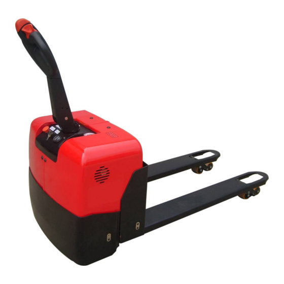
2. SPECIFICATION 2.1 LOCATION OF COMPONENTS Control Handle Caster Wheel Battery Indicator CURTIS 803 Pump Station Start Key Switch Lift Cylinder Emergency Button Load Roller Drive Wheel Battery CONTROL HANDLE 1. Raise/Lower buttons – Rocker switches adjusting fork height. 2. FWD/BWD/REV –Control travel button... -
Page 13: Specification Sheets
2.2 SPECIFICATION SHEETS Model of manufacture LPT15 Power supply (electric, diesel, petrol, gas, mains electric Type of operation (hand, pedestrian, stand on, rider pedestrian Capacity / rated load 1500 Load center distance Load distance Wheelbase 1217 Weight (including battery) Axle loadings laden... -
Page 14: Lubrication
2.3 LUBRICATION Hydraulic oil Hydraulic oil must have anti-wear qualities at least. It is not advisable to mix oils of different brands or types, as the may not contain the same required additives or be of comparable viscosities. Name: Thickened hydraulic oil. ISO Viscosity Grade Characteristics unit... -
Page 15: Electric System
3. ELECTRICAL SYSTEM 3.1 ELECTRICAL DIAGRAM WIRING DIAGRAM... - Page 16 CONNECTION DIAGRAM...
- Page 17 Code NL. Drawing No. Description Qty. BQ-20 Battery – 2x12V/80Ah FU01 DQ-38 Fuse, 80A WG-2-2 Motor for pump, DC24V/0.8kw WG-2-1 Relay for motor of pump, DC24V WG-2-3 Lower magnet valve, DC24V WG-8-4 Motor for traction, DC24V/0.75kw WG-8-11 Brake, DC24V DQ-3 Main relay C100/120 DC24V DQ-13 Controller CURTIS 1243C-4381...
-
Page 18: Installation Of Electrical
Code NL. Drawing No. Description Qty. 1000433008 DQ-LPT15DC-X1 Battery cable 1000433011 DQ-LPT15DC-X4 Control cable 1000433017 DQ-LPT15DC-X10 Drive motor cable 3.2 INSTALLATION OF ELECTRIC Micro switch Z-15GW2 Washer Screw Screw Rubber Cover Clip Horn DC24V Battery – 12V/80Ah Screw Washer Lock LKS-101A Screw Screw Emergency button ZDK31-250... -
Page 19: Drive Wheel
3.3 DRIVE WHEEL Type: 3EL-DC-0.75 Drive Motor Model HS XQT-0.75-1DH1U Rate voltage DC 24V R.P.M 3200rpm Rate output 1.0kw Rate hour 60 min. Rated current 45 A Amperager rating- max 6.4A Amperager rating- min 3.5A Insulation class F class Electromagnetic Brake Model G027-REB0908X-R Rate voltage... - Page 20 25A DURATION OF DISCHARGING CURVE (ENVIRONMENTAL TEMPERATURE = 25 100% DURATION OF DISCHARGING LIFE TEST CURVE ( ENVIRONMENTAL TEMPERATURE = CHARGING RATE...
-
Page 21: Charger
3.6 CHARGER Type: QQE192-8CH17-26A CHARGER SPECIFICATION Output current Max. output power battery capacity Input voltage Output voltage range 240W 40AH-100AH 230Vac +28.2Vdc ENVIRONMENTAL CONDITION Item Technical specification Unit Remark Humidity 5%-95% With package Altitude ≦3000 Work normally Cooling Natural convection cooling Working under full load ELECTRICAL CHARACTERISTICS Input characteristics... - Page 22 Protection characteristics Item Technical requirements Unit Remark Maximum output Voltage protected voltage The charger software limits the maximum output Software overload voltage to a level suitable for the connected battery voltage protection system When the internal temperature rises to 85℃,it turns into pulse charge mode.
- Page 23 HANDLE LED PLUG\WIRTING DIAGRAM FAN PLUG CABLE DIAGRAM CHARGING RELAY PLUG/ WIRING DIAGRAM –(SPM CHARGE ONLY)
-
Page 24: Curtis Controller
3.7 CURTIS CONTROLLER... - Page 25 CONNECTIONS Low Current Connections A 16-pin Molex low current connector in the controller provides the low current logic control connections: CAN Hi Pin 1 input /output #1 Pin 2 input /output #2 Pin 3 driver output #1(main contactor driver output ) Pin 4 input /output #3 auxiliary driver output (typically...
- Page 26 High Current Connections Three tin-plated solid copper bus bars are provided for high current connections to the battery (B+ and B-) and the motor armature (M-). Cables are fastened to the bus bars by M8 bolts. The 1243C case provides the capture nuts required for the M8 bolts. The maximum bolt insertion depth below the surface of the bus bar is 1.3 cm (1/2").
- Page 27 Time to reach full braking current limit in Mode 4 M4 BRAKE RATE M4 BRAKING RATE 0.1 to 3 when a direction change is made Defines throttle response to the rate of throttle QUICK START QUICK START 0 to 10 change.
- Page 28 A low side driver that can be programmed to drive a variety of E-M brake options, hourmeter, pump or AUX TYPE AUXILIARY DRIVER TYPE Types 0 - 5 brush motor contactor. This driver is short circuit protected Programmable time delay between throttle release AUXILIARY DRIVER TURN...
- Page 29 1.Improper sequence of KSI,interlock,and Follow proper direction inputs. sequence;adjust throttle if 2.Wrong SRO type selected. necessary;adjust 3.Interlock or direction switch circuit open. programmable if necessary. 4.Sequencing delay too short. 1.Throttle input wire open. THROTTLE When Throttle Wiper High 2.Throttle input wire shorted to B+ or B-. FAULT 1 input returns to valid range.
- Page 30 CURTIS 1311 HANDHELD PROGRAMMER The Curtis 1311 handheld programmer provides programming, diagnostic, and test capabilities for the controller. The power for operating the programmer is supplied by the host controller via a 4-pin Molex connector. The programmer includes a 7-line alphanumeric LCD display, rockertype keys for navigating through the display and for modifying parameters (+/-), and three keys that can be used as bookmarks.
- Page 31 seconds, until the Bookmark Set screen is displayed. To jump to a set bookmark location, quickly press the appropriate bookmark key (1, 2, or 3). Note that the bookmarks are not permanently stored in the programmer. They are cleared when the programmer is unplugged. The bookmark keys can be used to make parameter adjustment easier.
-
Page 32: Battery Indicator
3.8 BATTERY INDICATOR Type: CURTIS 803RB2448BCJ3010 Front View Rear View TERMINAL ASSIGNMENT Pin 7 or 8 = Battery +. Single voltage models: Pin 8 to battery +; Pin 7, open. Dual voltage models: When vehicle voltage is the higher voltage of the 2 operating voltages, Pin 8 connects to battery +; Pin 7, open. - Page 33 Pin 4 = Relay. Pin 4 also connects in series with the circuit to be switched at empty. HOUR METER CONTROL LINES & IMPEDANCE SPECIFICATIONS Min. Impedance Low Voltage (max.) Hight Voltage (min.) HRM+ HRM- 5.0VDC 15.0VDC 80kΩ 20 kΩ HOUR METER CONTROL LOGIC Pin 1 (HRM-) Pin 6 (HRM+)
-
Page 34: Replacing The Electric Parts
3.9 REPLACING THE ELECTRICAL PARTS Remove screws. Then remove the right cover and left cover. REPLACING THE CHARGER Remove two screws. Disconnect 3 plugs. Then you can remove the charger and replace it. REPLACING THE FAN Disconnect two screws, then you can remove the fan and replace it. - Page 35 REPLACING THE BATTERY After removing the charger and fan, remove two screws (No. 1), removing the mounting plate for the charger (No.2). Remove the bolts, nuts, washers, which fix the power cable ( +, - ) to the battery. Remove the bolt (No.5), washer (No.4), remove the mounting plate for battery (No.
- Page 36 Open the mounting plate for controller, key switch, etc. REPLACING THE BATTERY INDICATOR Remove two plastic nuts, take away the “U” clamp, remove the 8 - pins connector. Then you can remove the battery indicator and replace it. REPLACING THE FUSE Open the cover of the fuse seat, then you can remove the fuse and replace it.
- Page 37 REPLACING OF THE CONTROLLER When reconnecting the controller, be careful tto check the tightness of the power connection nut, Be sure to check the terminal connections. When recoonecting the 1/4” terminals marked (S1-left and S2-right) ensure these connections are not reversed. Otherwise the drive motor polarity will be reversed and will be demage the unit.
-
Page 38: Tool For Repairing The Pin Of Electric Plug
3.10 TOOL FOR REPAIRING THE PIN OF ELECTRIC PLUG Application Figure Tool for removal of pins / sleeves Tool for application of pins / sleeves Tool for release of lock Tool for application of secondary locking 2 – pole Tool for application of secondary locking 4 – pole Tool for removal of pins / sleeves... -
Page 39: Hydraulic System
4. HYDRAULIC SYSTEM HYDRAULIC FLOW DIAGRAM INSPECTION OF HYDRAULIC OIL External appearance Smell Condition Countermeasure Fine Fine Clear and no discoloration Possible to use Inspect the viscosity and if fine Clear but the color becames brighte Fine Mixed with other oil it can be continuously used Color changed like milk. - Page 40 Disconnect the bolts (No.1). Remove the 2 bolts (No. 1), noto 2pcs washers (No.4) Then remove the power unit (No.3) Replace the new one. CLEANING OIL TANK AND FILTER Put the fork of the ground and drain out the hydraulic oil. ...
- Page 41 Plug Screw of port for adding oil is ventilate. When lower, the air will come out from the tank, it might take out little oil vapour. So, it might appear little oil stains on the plug after some time. It is not leak. Because the electric current of the Relay for the lifting motor is very big, and work continually hourly, the contact terminal of the relay is easy damaged.
-
Page 42: Replacing Of Cylinder
4.2 REPLACING OF CYLINDER REPLACING THE CYLINDER After remove the battery, and charger, you should remove the axle and link plate from the fram Step 1.1: Remove this screw. Pull out the retainer clip and remove towards the rear of the unit Step 1.2 Use a M8x25 (8.8T or better) - Page 43 Then, you can seprate them. LEFT VIEW LIGHT VIEW Remove 2 bolts, take away the retaining bracket for cylinder, then you can remove the cylinder and replace it. No. Part name No. Part name Y – ring, 45x 55x8 Hydraulic hose Piston rod, ...
-
Page 45: Drive Wheel
5. DRIVE WHEEL Part name Part name Retaining ring O - ring Bearing Cover Wheel Axle with gear Washer Box of gear Hexagonal Head Bolt M6X20 Gear Dust ring Retaining ring House of gear Retaining ring Washer Bolt M6x15 Dust ring Motor Brake Bolt M8x25... -
Page 46: Replacing The Wheel
5.1 REPLACING THE WHEEL Remove the mounting plate for the cable Remove the power cable from the motor Remove the plugs for the brake and Remove 10 bolts temperature sensor 2 guide pin holes 10 bolts holes 4 threaded wheel hub pulling bolt holes to assist in wheel removal,if necessary. -
Page 47: Replacing The Carbon Brush Kit
5.2 REPLACING THE CARBON BRUSH KIT Remove the steel shield which is wrapped around the motor, the carbon brushes will be visible once the shield is removed Remove the bolt which holds the carbon brush, Tilt in the pressure spring of the carbon brush with a screwdriver, then take out the carbon brush. -
Page 48: Replacing The Brake
REPLACING THE BRAKE Part name Part name Gaiter Spring Friction plate Carrier Body magnetic Screw Break disk Screw M5x45 Break anchor plate Remove 6 bolts Then you can replace the brake or adjust it. -
Page 49: The Brake Clearance Adjustment
5.4 BRAKE CLEARANCE ADJUSTMENT Brake coil must always be connected to the power (+24v), when energized the brake will dis engage. If the brake system loose power, while unit is use, the unit may loose speed, and motor may reduce excessive heat Step 1: Measure the resistance by multimeter(200Ω), and The Winding resistance: 25Ωnormal (+1,-1 Ω) - Page 50 Step 3: Adjust the brake spacer plate bolts in or out to adjust the Clearance of the brake plate. Be sure not to over tighten the bolts Step 4: Adjust the above-mentioned bolts counter clockwise. adjust 2-3 revolutions to reduce the spring tension.
-
Page 51: Control Handle
6. CONTROL HANDLE No. Part name No. Part name Bushing, 23/19*17*10 Air spring Handle mounting bracket Handle cable Shaft, 17 Micro switch Z-15GW2 Roll pin, 4x24 Screw, M4x25 Socket hex bolts M8x25 Cover Elastic washer 8 Screw, M4x10 Socket hexa bolts M8X16 Tillerarm... -
Page 52: Replacing Of The Control Handle
No. Part name No. Part name Butterfly left or throttle switch left Seesaw-left or toggle button left Button for horn Magnet holder for seesaw Spring Hinge spring Bearing for camshaft Contact base Magnet Belly switch cover Spring for belly botton switch Optional cover Socket hexagonal Screw, M6X10 Seesaw right or toggle button right... - Page 53 6 pin plug, must be firmly connected to the controller. Remove the screw to remove the circuit board Remove the bolt to remove the throttle lever once the bolt is removed from the throttle lever the opposing throttle lever and throttle shaft can be pulled out through the oppsoing side of the handle.
-
Page 54: Replacing Of The Air Spring And Micro Switch
connected to the cirsuit board and are servicable. 6.2 REPLACING OF THE AIR SPRING AND MICRO SWITCH Remove 4 bolts. The signal to the #2 pin of CURTIS1230C Micro Switch and Air Spring Ensure the micro switch is mounted in the correct position. The switch may require adjustment upon re-installation. -
Page 55: Caster Wheel
7. CASTER WHEEL 7.1 REMOVING OF THE CASTER WHEEL First, let the pallet truck to be slanting, then dismantle four screws. Note to help the nut when turning the screws. Then you can dismaantle the caster and replace it. 7.2 ADJUSTING THE PRESSURE FOR THE DRIVE WHEEL After using some time, the drive wheel might wear off, the pressure for the drive wheel will not be enough, and drive wheel can not bit into the ground and slip. -
Page 56: Trouble Diagnostics
8. TROUBLE DIAGNOSTICS 8.1 MAINTENANCE LIST Maintenance Time Interval Standard=● Refrigerating house=# 6 12 Inspection of any damage of bearing parts ● Chassis truck frame Inspection of all joints of bolts ● Inspection of noise and leakage of driving system ●... -
Page 57: Trouble Shoot
c) 500 hours after initial operation. 8.2 TROUBLE SHOOT...