
Related Manuals for Traffic Logix SAFEPACE Guardian Awareness

Summary of Contents for Traffic Logix SAFEPACE Guardian Awareness
- Page 1 RAFFIC OGIX ® G UARDIAN RAILER NSTALLATION UIDE Traffic Logix Speed Awareness Copyright © 2018 Traffic Logix Corporation All rights reserved.
- Page 2 Trademarks Traffic Logix® is a registered trademark of Logix ITS Inc. All other product and company names are trademarks or registered trademarks of their respective owners. This document may contain confidential and proprietary information of Traffic Logix Corporation and/or other third parties which is protected by copyright, trade secret and trademark law and may not be provided or otherwise made available without prior written authorization.
-
Page 3: Table Of Contents
ABLE OF ONTENTS Chapter 1 Introduction Description About this Guide Documentation Conventions Using Additional Customer Resources Documentation CD Online Customer Area Contacting Technical Support Chapter 2 Installing SafePace Guardian Positioning your SafePace Guardian and Trailer Selecting a Location for your Trailer Mounting a SafePace Guardian on a Trailer Mounting a Radar Sign on the Trailer Mounting the Camera and (Optional) Illuminator... -
Page 4: Introduction
Chapter 1 NTRODUCTION SafePace® Guardian Trailer Installation Guide p. 4... -
Page 5: Description
The SafePace Guardian Speed Camera System is an entry-level camera system offered as an accessory to Traffic Logix SafePace Radar Speed signs. This system detects speeds via the radar unit of the connected SafePace sign and captures images of vehicles that exceed the specified speed threshold. The system tracks vehicles in one lane only and is ideal for low-volume roads such as campuses and private communities. -
Page 6: About This Guide
About this Guide About this Guide This installation guide is meant for anyone who needs to physically install a SafePace Guardian Speed Camera System on a SafePace Cruiser LT. It covers the following topics: Deciding where and how to install your SafePace Guardian Speed Camera System »... -
Page 7: Using Additional Customer Resources
Provides convenient access to the latest versions of our software applications and utilities. Support Videos Provides access to several videos that can help you get up to speed with your Traffic Logix product. Product Documentation Provides access to the most recent versions of our product documentation. -
Page 8: Installing Safepace Guardian
Chapter 2 NSTALLING UARDIAN SafePace® Guardian Trailer Installation Guide p. 8... -
Page 9: Positioning Your Safepace Guardian And Trailer
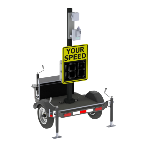
Positioning your SafePace Guardian and Trailer Positioning your SafePace Guardian and Trailer SafePace Guardian needs to be located at the side of the road being monitored with the camera, (optional) illuminator and sign pointed towards oncoming traffic. This allows the camera to capture the front license plate of the passing vehicles while drivers are alerted of their speeds. -
Page 10: Mounting A Safepace Guardian On A Trailer
Mounting a SafePace Guardian on a Trailer Mounting a SafePace Guardian on a Trailer Mounting your SafePace Guardian requires that you mount and connect each of the following components of the system: The radar speed sign » The Guardian camera »... - Page 11 Mounting a Radar Sign on the Trailer This allows you to easily slide the sign onto the pole bracket then lock it in place with the included key. You can just as easily remove it from the bracket once it is unlocked. Installing the Sign Bracket To install the Sign Bracket: Attach the Sign Bracket to the backside of the sign using the included hardware.
- Page 12 Mounting a Radar Sign on the Trailer Figure 5: Trailer mast with radar sign Figure 6: Pole bracket with nuts placed on the inside of the sign bracket Mounting and Dismounting the Sign After you install the mounting brackets, you can easily mount the radar speed sign sign by sliding it down onto the Pole Bracket.
- Page 13 Mounting a Radar Sign on the Trailer To mount the sign: Position the sign above the bracket. Slide the sign down the bracket. Use the supplied key to lock the sign in place. To dismount the sign: Unlock the sign. SafePace®...
-
Page 14: Mounting The Camera And (Optional) Illuminator
Mounting the Camera and (Optional) Illuminator Slide the sign up and off of the Pole Bracket. Mounting the Camera and (Optional) Illuminator Use the included mounting bracket to mount the camera and illuminator just below the solar panel and above the radar sign on the mast. Figure 7: Trailer mast with camera and illuminator The mounting bracket holds both the camera and the illuminator. - Page 15 Mounting the Camera and (Optional) Illuminator To attach the camera and illuminator to the mounting plate: Use the supplied mounting screws to attach the Camera and Illuminator to the mounting plate as shown » in the following illustration. Installing the Pole Bracket on the Mast You need to install the pole bracket on the mast of the trailer.
- Page 16 Mounting the Camera and (Optional) Illuminator Figure 9: Pole bracket mounted with nuts on the inside Mounting the camera and illuminator on the mast After you have installed the pole bracket the mounting plate with the camera and illuminator slides into place easily.
-
Page 17: Mounting The Solar Panel
Mounting the Solar Panel Use the supplied key to lock the sign in place. To dismount the camera and illuminator: Unlock the bracket. Slide the mounting plate up and off of the pole bracket. Mounting the Solar Panel You need to mount the solar panel (with the attached bracket) at the top of the trailer's mast. To mount the solar panel: Use the supplied bolts to attach the solar panel and bracket to the top of the trailer's mast. - Page 18 Mounting the Solar Panel Ideally, the solar panel should be angled 15 degrees above the latitude of the installation site. For example, if the latitude of the installation site is 45 degrees then the solar panel should be installed at an angle of 60 degrees, as shown. You can easily obtain the latitude of the installation site from mapping software or for free by doing an internet search for "latitude your_city"...
-
Page 19: Connecting The Components To The Sign
Connecting the Components to the Sign Connecting the Components to the Sign After you have mounted all of the components on the trailer you need to connect everything with the sign. Along the bottom of the sign you will find connectors or cables for the camera (Ethernet and power), illuminator, and the trailer battery box. - Page 20 Connecting the Sign to the Solar Panel Figure 12: Solar panel wires and connectors on the back of the solar panel Figure 13: Wires and connectors from the sign enclosure. To prevent damage to the solar charger, connect the solar panel to the sign before ARNING connecting the sign to the battery pack on the trailer.
- Page 21 Connecting the Sign to the Solar Panel Slide the connectors together until you hear a click and you can no longer slide them apart easily. Once connected the cables should look like the following: Before ever doing any maintenance on a sign, it is critical that the power is first turned off. ARNING This will prevent accidental electrical shock that can be fatal and that can also damage electrical components.
-
Page 22: Connecting The Sign To The (Optional) Illuminator
Connecting the Sign to the (Optional) Illuminator To prevent damage to the solar charger, connect the solar panel to the sign before ARNING connecting the sign to the battery pack on the trailer. To wire the solar panel to the sign: Align the solar panel and the sign connectors, then insert the sign connector into the solar panel connector. -
Page 23: Connecting The Camera To The Sign
Connecting the Camera to the Sign Connecting the Camera to the Sign The Guardian camera has two cables that you need to connect to the radar sign. There is a power cable through which the camera draws power from the sign. And there is an Ethernet cable for data transfer between the sign and camera. -
Page 24: Connecting The Sign To The Battery Box
Connecting the Sign to the Battery Box Connect the camera's Ethernet cable to the Ethernet port on the sign. Unscrew the cover from the sign's Ethernet port. Insert the Ethernet cable from the camera into the sign's Ethernet port. Screw the cover of the Ethernet cable on over the connection. Be careful not to over-tighten it. Connecting the Sign to the Battery Box You need to connect the sign to the battery box so that the solar panel can charge the batteries and the sign can draw power from the batteries when needed. - Page 25 Connecting the Sign to the Battery Box To connect the sign to the battery box: Lift the cover of the connector on the battery box, then insert the battery cable from the sign. » There is a ridge on the cable connector that needs to be at the top of the connection. As a result the cable connector can only be properly inserted one way.
-
Page 26: Safepace Guardian Operation And Maintenance
Chapter 3 UARDIAN PERATION AND AINTENANCE SafePace® Guardian Trailer Installation Guide p. 26... -
Page 27: Pointing The Camera
Pointing the Camera Pointing the Camera As part of the installation procedure you need to make sure that the Guardian camera is properly aligned. To point the camera: Place a marker, for example a traffic cone, at the edge of the roadway approximately 12 meters from the camera. - Page 28 Pointing the Camera Select the General tab. In the General Settings box, click the Units of speed and distance drop down, then select the units you want to use. Set the following parameters: Parameter Description Device mounting height Specifies the height of the camera above the roadbed. If the actual height is less than 2 meters, set this value to 2.
- Page 29 Pointing the Camera While you can set other parameters (e.g. Location, Speed limit, Timezone) as well at this time, the parameters listed in the previous table are the only ones necessary in order to point the camera. When you are finished, click Save Settings.
-
Page 30: Operating Your Camera
Operating Your Camera Operating Your Camera After you have mounted, aligned and powered on your camera, you can connect to and manage it remotely using SafePace Cloud. For information on operating your camera with SafePace Cloud, refer to the SafePace Cloud Online User Guide. -
Page 31: Warranty
Terms of Use and any Applicable Safety Laws. Buyer agrees that there shall be no coverage or benefits of any kind under this limited warranty if it is determined by Traffic Logix that the Product was not installed or used in accordance with the Conditional Terms of Use or Applicable Safety Laws, or if the Product has been SafePace®... - Page 32 Warranty altered in any way by anyone other than Traffic Logix, or if the Product has been subject to any misuse or accident. In addition, Buyer assumes and agrees to indemnify Traffic Logix for all risk, liability or expense that results from any installation or use of the Product that is not in accordance with the Conditional Terms of Use or any Applicable Safety Laws.
Need help?
Do you have a question about the SAFEPACE Guardian Awareness and is the answer not in the manual?
Questions and answers