Table of Contents
Advertisement
Available languages
Available languages
Quick Links
CAUTION / ATTENTION / ACHTUNG / ATENCIÓN / ATTENZIONE / AANDACHT / UWAGA
EN
The manual should be read prior to beginning installation and keep after
FR
Le manuel doit être lu avant de commencer l'installation et conservé après
DE
Das Handbuch sollte vor Beginn der Installation gelesen und nach der Installation aufbewahrt werden.
ES
El manual debe ser leído antes de comenzar la instalación y mantenerlo después
PT
O manual deve ser lido antes do início da instalação e mantido após
IT
Il manuale deve essere letto prima di iniziare l'installazione e conservato dopo
NL
De handleiding moet voor het begin van de installatie worden gelezen en na de installatie worden bewaard
PL
Instrukcję należy przeczytać przed rozpoczęciem instalacji i zachować ją po
INSTRUCTION MANUAL / NOTICE DE MONTAGE / MONTAGEANLEITUNG / MANUAL DE MONTAJE / MANUAL DE MONTAGEM / MANUALE DI MONTAGGIO / MONTAGEHANDLEIDING / INSTRUKCJA MONTAŻU
TANKER B250
STW-000023
STI-000023
EN
FR
DE
!
ES
PT
IT
NL
PL
Advertisement
Table of Contents

Related Manuals for Casanoov TANKER B250


Summary of Contents for Casanoov TANKER B250
- Page 1 TANKER B250 STW-000023 STI-000023 CAUTION / ATTENTION / ACHTUNG / ATENCIÓN / ATTENZIONE / AANDACHT / UWAGA The manual should be read prior to beginning installation and keep after Le manuel doit être lu avant de commencer l’installation et conservé après Das Handbuch sollte vor Beginn der Installation gelesen und nach der Installation aufbewahrt werden.
- Page 2 Manual translated from English version using automatic translator. In case of question please refer to english version.
- Page 3 CAUTION • This product must be installed by well-trained skilled personnel in compliance with the safety regulations the field of residential and commercial swing gate opener devices. Unqualified personnel may damage the instruments and cause harm to the public. • Electric Power must be disconnected prior to installation, or performing any maintenance. •...
-
Page 4: Tools Required
Tools Required (Required) (Required) (Required) (Required) (Required) (Required) (Required) (Required) (Recommended) - Page 5 Serial Number...
-
Page 6: Product Overview
Product overview 350 mm Technical specifications Motor voltage : 24VDC 60W Max single vent weight : 300 KG Input power : 220VAC±10%/110VAC±10% Environment Temperature : -20°C ~ +50°C Rotational speed : 300 RPM Protection Class : IP55 Arm’s extended speed : 2.5 cm/s Max gate open angle : 110 degree Arm’s max travel : 300 mm Rated capacity : 1090 N... -
Page 7: Manual Unlocking
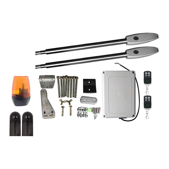
Swing Gate automation Features & Options Swing gate opener motor Flash lamp Control box Remove auto-close and keep the central stop Remote control Photo cells Manual unlocking Open the gate manually : Use the manual override key to release the clutch to open or close the gate manually. - Page 8 General options and accessories • When Gate is Obstructed : Gate stops. • Optional : The Gate Opener Controller can be connected to a solar system, a Flash light warning, a photocell, back up battery, keypad and other access control devices. •...
- Page 9 WARNING Adjusting different angles of Rear Bracket Fixed Plate to fit different Installing condition. 181.5mm WARNING Fixing motor on bracket. Watch that the electric cable is in the proper position ! WARNING CABLE MUST NOT BE INSTALLED ABOVE THE MOTOR ARM. IT MAY PINCH AND STRIP THE CABLE AND CAUSES ELECTRIC SHOCK.
- Page 10 Installation of Extended End Motor Arms to Gates USE BUBBLE LEVEL Extended arm - 1 cm Before installing : extend the motor’s arm to its maximum size then retract inside around 1cm. Ensure that the Post bracket height is in the same exact level with the gate bracket height.
- Page 11 Installation of Motor’s Arms to Gates Drill 2 Holes of 10.2mm Diameter With Space 68 to 77 mm Between 2 holes. Locate the 2 Slotted Holes Gate Bracket above the Drilled Holes. Place the End Motor Bracket to the Gate Bracket using the Appropriate Bolts and Tighten Properly. Please note these bolts used to fixed front bracket to the gate are not provided due to the thickness of each gate is different.
-
Page 12: Control Board Wiring Diagram
Control board wiring diagram 1 2 3 4 5 6 7 8 9 10 11 12 13 14 15 16 17 18 SIDE terminal is used for connecting any external device that operates double gate. COM is COMMON used for connecting the “ground” of lock. 24V DC lock output—the NA terminal which used for COM terminal is COMMON used for connecting the “ground”... - Page 13 TURN OFF ELECTRICY BEFORE CONNECTING THE CONTROL BOARD TO THE 230V AND TO ACCESSORIES. 25 26 1 2 3 4 5 6 7 8 9 10 11 12 13 14 15 16 17 18 19 2 side and 1 side are for connect open device, such as push but- ton, wired keypad, camera video, GSM controller etc...
-
Page 15: Remote Control
Remote control Button “1” depressed to operate single gate; Button “2” depressed to operate double gate; Button “3” depressed for alarm output Program new remote control: > First step Press the LEARN button on the control board [29] for about 1 second, the indicator LED would turn off, then now means have already enter learning Second step: Press any button of the new remote control for about 2 second, then digital display would show the remote number while indicator LED on board starts flash four times with one buzzer sound then now... - Page 16 MANUAL RANGE DEFAULT MARKED SETTING ( INC +/ DEC - ) SETING ON BOARD Soft start time setting 0-6 s SOFT START Motor 1 low speed running stall 0-20Level 6th Level Ml LOW OVER force adjustment. LOAD Motor 1 high speed running stall 0-20Level 10th Level M1 HI OVER...
- Page 17 Setting of the control board ner is on Motor 2 high speed running stall force ad- 1. To set the soft start time: justment. There is 0-20 levels for optional. Each time When digital display indicate P0, the gate opener you press and release the [INC+] button, the figure is on the soft start time setting.
- Page 18 button, the figure increase by 1; each time you press 8. To set lock time: and release the [DEC-] button, the figure decrease by 1. Press the [FUN] button to store the data when When digital display indicate Pb, the gate opener is the open interval time chosen, then the open interval on lock time control setting.
- Page 19 FLASH LAMP WARNING Safety Instruction 1. For security, please read the user manual carefully before initial operation; 2. Please be sure the power is off before connecting, the product is produced without fuse; Flash lamp specifications Working voltage 12-265 VAC/DC <...
- Page 20 Photocells Connect terminal 4 to the «COM» of photocell RX. Connect terminal 5 to the «IR»of photocell RX. Terminal is supplying power for external device. So, connect terminal 7 to the «+» of photocell RX and TX. Connect terminal to 5 the «-»of photocell RX and TX. 13 14 15 16 17 18 19 11 12...
-
Page 21: Declaration Of Ce Conformity
Declaration of CE conformity Technical report number : DL-2020061821E / DL-2020061792S Hoortrade SAS 4 bis avenue jean françois raclet 69007 lyon France Declares that the following product/ SKU : JJ-PKM C022 – HOORTRADE reference : STI-000023 Satisfies the essential requisites established in following directives : Low Voltage Directive EN 60335-1 :2012+A11 :2014+A13 :2017+A1 :2019+A14 :2019 And satisfies the following standards :... - Page 22 ATTENTION • Ce produit doit être installé par un personnel qualifié et bien formé, en conformité avec les règles de sécurité en vigueur dans le domaine des dispositifs d’ouverture de portails à battants résidentiels et commerciaux. Un personnel non qualifié peut endommager les instruments et causer des dommages au public.
-
Page 23: Outils Nécessaires
Outils nécessaires (Obligatoire) (Obligatoire) (Obligatoire) (Obligatoire) (Obligatoire) (Obligatoire) (Obligatoire) (Obligatoire) (Recommandé) -
Page 24: Numéro De Série
Numéro de série... -
Page 25: Spécifications Techniques
Dimensions des produits Spécifications techniques Tension du moteur : 24VDC 60W. Poids maximal d’un évent simple : 300 KG Puissance d’entrée : 220VAC±10%/110VAC±10% Température de l’environnement : -20°C ~ +50°C Vitesse de rotation : 300 RPM Classe de protection : IP55 Vitesse d’extension du bras : 2.5 cm/s Angle d’ouverture maximum de la porte : 110 degrés Course maximale du bras : 300 mm... - Page 26 Automatisation du portail battant : Caractéristiques et options Moteur de l’ouvre-porte à battants Lampe flash Boîte de contrôle Enlever la fermeture automatique et garder l’arrêt Télécommande Cellules photoélectriques Dévérouillage manuel Ouvrez le portail manuellement : Utilisez la clé de commande manuelle pour débrayer l’embrayage afin d’ouvrir ou de fermer le portail manuellement.
- Page 27 Options générales et accessoires • Quand la porte est obstruée : La porte s’arrête. • Facultatif : Le contrôleur d’ouverture de la porte peut être connecté à un système solaire, à un témoin lumineux, à une cellule photoélectrique, à une batterie de secours, à un clavier et à d’autres dispositifs de contrôle d’accès. •...
- Page 28 AVERTISSEMENT Ajustement des différents angles de la plaque fixe du support arrière pour s’adapter aux différentes conditions d’installation. 181.5mm FIXATION DU MOTEUR SUR LE SUPPORT Veillez à ce que le câble électrique soit dans la bonne position ! DANGER WARNING LE CÂBLE NE DOIT PAS ÊTRE INSTALLÉ...
- Page 29 Installation des bras motorisés sur le portail UTILISER UN NIVEAU UTILISER UN NIVEAU Bras déployé - 1 cm Avant l’installation : étendre le bras du moteur jusqu’à sa taille maximale puis le rétracter à l’intérieur d’environ 1 cm. Assurez-vous que la hauteur du support du poteau est exactement au même niveau que celle du support du portail.
- Page 30 Installation des bras du moteur aux portails Percez 2 trous de 10,2 mm de diamètre avec un espacement de 68 à 77 mm entre les 2 trous. Placez le support de porte à 2 trous fendus au-dessus des trous percés. Placez le support du moteur d’extrémité...
- Page 31 Schéma de câblage de la carte de contrôle : 1 2 3 4 5 6 7 8 9 10 11 12 13 14 15 16 17 18 Le terminal SIDE est utilisé pour connecter tout dispositif externe qui actionne une double porte. COM est COMMON utilisé...
- Page 32 COUPEZ L’ÉLECTRICITÉ AVANT DE BRANCHER LE TABLEAU DE COMMANDE AU 230V ET AUX ACCESSOIRES. 25 26 1 2 3 4 5 6 7 8 9 10 11 12 13 14 15 16 17 18 19 2 côtés et 1 côté sont pour les appareils ouverts, tels que les boutons poussoirs, les claviers câblés, les caméras vidéo, les...
- Page 34 Télécommande Bouton «1» enfoncé pour actionner une porte simple ; Bouton «2» enfoncé pour actionner une porte double Bouton «3» enfoncé pour la sortie de l’alarme Programmer une nouvelle télécommande : > Première étape : Appuyez sur le bouton LEARN du panneau de contrôle [29] pendant environ 1 seconde, le voyant lumineux s’éteint, ce qui signifie que vous avez déjà...
- Page 35 RÉGLAGE GAMME RÉGLAGE PAR MARQUÉ SUR LA CARTE DE CONTRÔLE MANUEL ( INC +/ DEC - ) DÉFAUT Réglage de l’heure de démarrage 0-6 s SOFT START progressif Réglage de la force de décrochage du moteur 1 Niveau 0-20 6ème niveau Ml LOW OVER à...
- Page 36 Réglage du panneau de contrôle 2d-- Lorsque l’affichage numérique indique P4, l’ouvre-bar- 1. Pour régler l’heure de démarrage progressif : rière est sur le réglage de la force de décrochage à grande Lorsque l’affichage numérique indique P0, l’ouvre-porte vitesse du moteur 2. Il y a de 0 à 20 niveaux pour l’option. est sur le réglage de l’heure de démarrage progressif.
- Page 37 y a 0-10s pour l’option. 0s signifie que les doubles portes clignote que lorsque la porte est en marche. Chaque fois s’ouvrent simultanément. «1» signifie que le moteur 1 que vous appuyez et relâchez le bouton [INC+], le chiffre commence à s’ouvrir 1 seconde avant que le moteur 2 augmente de 1 ;...
- Page 38 LAMPE FLASH AVERTISSEMENT Instruction de sécurité 1. Pour des raisons de sécurité, veuillez lire attentivement le manuel d’utilisation avant la première utilisation ; 2. Veuillez vous assurer que l’alimentation électrique est coupée avant de brancher le produit, celui-ci étant fabriqué sans fusible ; Spécifications des lampes flash Tension de fonctionnement 12-265 VAC/DC...
- Page 39 Cellules photoélectriques Connectez la borne 4 au «COM» de la cellule photoélectrique RX. Connectez la borne 5 au «IR» de la cellule photoélectrique RX. La borne fournit l’alimentation pour le dispositif externe. Donc, connectez la borne 7 au «+» de la cellule photoélectrique RX et TX. Connectez le terminal 5 au «-»...
-
Page 40: Déclaration De Conformité Ce
Déclaration de conformité CE Numéro du rapport technique : DL-2020061821E / DL-2020061792S Hoortrade SAS 4 bis avenue jean françois raclet 69007 lyon France Déclare que le produit suivant SKU : JJ-PKM C022 – HOORTRADE référence : STI-000023 Satisfait aux exigences essentielles établies dans les directives suivantes : Low Voltage Directive EN 60335-1 :2012+A11 :2014+A13 :2017+A1 :2019+A14 :2019 Et satisfait aux normes suivantes :... - Page 41 VORSICHT: • Dieses Produkt muss von gut ausgebildetem Fachpersonal unter Einhaltung der Sicherheitsvorschriften im Bereich der Drehtorantriebe für den privaten und gewerblichen Bereich installiert werden. Unqualifiziertes Personal kann die Geräte beschädigen und der Öffentlichkeit Schaden zufügen. • Vor der Installation oder der Durchführung von Wartungsarbeiten muss die Stromversorgung unterbrochen werden.
-
Page 42: Erforderliche Werkzeuge
Erforderliche Werkzeuge (Erforderlich) (Erforderlich) (Erforderlich) (Erforderlich) (Erforderlich) (Erforderlich) (Erforderlich) (Erforderlich) (Empfohlen) - Page 43 Seriennummer...
-
Page 44: Technische Spezifikationen
Abmessungen der Produkte Technische Spezifikationen Motorspannung : 24VDC 60W. Maximales Gewicht einer einzelnen Entlüftung : 300 KG Eingangsleistung : 220VAC±10%/110VAC±10% Umgebungstemperatur : -20°C ~ +50°C Umdrehungsgeschwindigkeit : 300 RPM Schutzklasse : IP55 Geschwindigkeit bei ausgefahrenem Arm : 2.5 cm/s Max. Öffnungswinkel des Tores : 110 Grad Maximaler Verfahrweg des Arms : 300 mm Schubkraft : 1090 N Kontinuierliche Laufzeit : 5 Minuten... -
Page 45: Manuelle Entriegelung
Funktionen und Optionen der Swing Gate-Automatisierung Motor des Drehtoröffners Blitzlampe Steuerkasten Autozufahrt entfernen und den Zentralanschlag beibehalten Fernsteuerung Fotozellen Manuelle Entriegelung Öffnen Sie das Tor von Hand : Zum manuellen Öffnen oder Schließen des Tores die Kupplung mit dem Handbetätigungsschlüssel lösen. - Page 46 Allgemeine Optionen und Zubehör • Wenn das Tor versperrt ist : Das Tor bleibt stehen. • Optional : Der Toröffner-Controller kann an ein Solarsystem, eine Blitzlichtwarnung, eine Fotozelle, eine Backup-Batterie, ein Tastenfeld und andere Zugangskontrollvorrichtungen angeschlossen werden. • Geschwindigkeitssteuerung : Die Geschwindigkeit beim Öffnen und Schließen des Tores kann eingestellt werden. •...
- Page 47 WARNUNG : Einstellung verschiedener Winkel der festen Platte der hinteren Halterung zur Anpassung an unterschiedliche Installationsbedingungen. 181.5mm MOTOR AUF KONSOLE BEFESTIGEN Achten Sie darauf, dass sich das Elektrokabel in der richtigen Position befindet ! GEFAHR WARNING DAS KABEL DARF NICHT OBERHALB DES MOTORARMS INSTALLIERT WERDEN. ES KANN DAS KABEL EINKLEMMEN UND ABISOLIEREN UND EINEN ELEKTRISCHEN SCHLAG VERURSACHEN.
- Page 48 Installation von verlängerten Endmotorarmen an Toren VERWENDUNG EINER VERWENDUNG EINER WASSERWAAGE WASSERWAAGE - 1 cm Verlängerter Arm Vor der Installation : den Arm des Motors bis zur maximalen Größe ausfahren und dann etwa 1 cm nach innen zurückziehen. Vergewissern Sie sich, dass die Höhe der Pfostenkonsole genau mit der Höhe der Torkonsole übereinstimmt.
- Page 49 Installation von Motorarmen an Toren Bohren Sie 2 Löcher von 10,2 mm Durchmesser mit einem Abstand von 68 bis 77 mm zwischen 2 Löchern Platzieren Sie die Anschnitthalterung mit 2 Schlitzlöchern über den gebohrten Löchern. Platzieren Sie die Endmotorhalterung mit den entsprechenden Schrauben an der Torhalterung und ziehen Sie sie richtig fest.
- Page 50 Schaltplan der Steuertafel: 1 2 3 4 5 6 7 8 9 10 11 12 13 14 15 16 17 18 Der SIDE-Terminal wird für den Anschluss aller externen Geräte verwendet, die ein Doppelgate COM ist COMMON, der für den Anschluss der «Masse» des Schlosses betreiben verwendet wird.
- Page 51 SCHALTEN SIE DIE ELEKTRIK AUS, BEVOR SIE DIE STEUERPLATINE AN DIE 230V UND AN ZUBEHÖR ANSCHLIESSEN. 25 26 1 2 3 4 5 6 7 8 9 10 11 12 13 14 15 16 17 18 19 2 Seiten und 1 Seite sind für conncet offenes Gerät, wie z.B.
- Page 53 Fernsteuerung Taste «1» gedrückt, um einfaches Tor zu betätigen; Taste «2» gedrückt, um doppeltes Tor zu betätigen Gate; Taste «3» für Alarmausgang gedrückt Neue Fernbedienung programmieren: > Erster Schritt: Drücken Sie den LEARN-Knopf auf der Steuerplatine [29] für ca. 1 Sekunde, die LED-Anzeige würde erlöschen, dann bedeutet jetzt, dass Sie bereits in den zweiten Schritt des Lernens eingetreten sind: Drücken Sie eine beliebige Taste der neuen Fernbedienung für ca.
- Page 54 MANUELLE BEREICH STANDARD- AUF KONTROLLKARTE EINSTELLUNG MARKIERT ( INC +/ DEC - ) EINSTELLUNG Einstellung der Softstart-Zeit 0-6 s SOFT START Motor 1 Niedertourige Einstellung der 0-20Stufe 6. Ebene Ml LOW OVER Überziehkraft. LOAD Motor 1 Hochgeschwindigkeits- 0-20Stufe 10. Ebene M1 HI OVER Laufüberziehkrafteinstellung.
- Page 55 Einstellung der Steuertafel der [DEC-]-Taste verringert sich die Zahl um 1. Drücken 1. So stellen Sie die Softstartzeit ein: Sie die [FUN]-Taste, um die Daten zu speichern, wenn die Wenn die Digitalanzeige P0 anzeigt, befindet sich gewählte Überziehkraftstufe und dann die Einstellung der der Toröffner in der Einstellung der Softstart-Zeit.
- Page 56 5b. Wenn die Digitalanzeige P8 anzeigt, befindet sich Die Schleusenkontrollzeit bedeutet die Zeit, in der wir die der Toröffner in der Einstellung der Schließintervallzeit. Schleuse kontrollieren könnten. Es gibt 0-1 für optional. Optional sind 0-10 s möglich. 0s bedeuten, dass Doppeltore «0»...
- Page 57 BLITZLAMPE WARNUNG Sicherheitsanweisung 1. Bitte lesen Sie zur Sicherheit vor der Inbetriebnahme das Benutzerhandbuch sorg- fältig durch; 2. Bitte vergewissern Sie sich vor dem Anschließen, dass der Strom abgeschaltet ist; das Produkt ist ohne Sicherung hergestellt; Spezifikationen für Blitzlampen Arbeitsspannung 12-265 VAC/DC Belastbarkeit <...
- Page 58 Fotozellen Verbinden Sie Klemme 4 mit dem «COM» der Fotozelle RX. Klemme 5 an den «IR»-Anschluss der Fotozelle RX anschließen. Der Anschluss liefert Strom für ein externes Gerät. Verbinden Sie also Klemme 7 mit dem «+» der Fotozelle RX und TX. Verbinden Sie Klemme 5 mit dem «-»...
-
Page 59: Eg-Konformitätserklärung
EG-Konformitätserklärung Numéro du rapport technique : DL-2020061821E / DL-2020061792S Hoortrade SAS 4 bis avenue jean françois raclet 69007 lyon France Erklärt, dass das folgende Produkt/ SKU : JJ-PKM C022 – HOORTRADE Referenz : STI-000023 Erfüllt die wesentlichen Anforderungen, die in folgenden Richtlinien festgelegt sind Low Voltage Directive EN 60335-1 :2012+A11 :2014+A13 :2017+A1 :2019+A14 :2019 Und erfüllt die folgenden Normen:... - Page 60 PRECAUCIÓN: • Este producto debe ser instalado por personal calificado y bien entrenado en cumplimiento de las normas de seguridad en el campo de los dispositivos abridores de puertas batientes residenciales y comerciales. El personal no cualificado puede dañar los instrumentos y causar daños al público.
-
Page 61: Herramientas Necesarias
Herramientas necesarias (Requerido) (Requerido) (Requerido) (Requerido) (Requerido) (Requerido) (Requerido) (Requerido) (Recomendado) -
Page 62: Número De Serie
Número de serie... -
Page 63: Especificaciones Técnicas
Dimensiones de los productos Especificaciones técnicas Voltaje del motor : 24VDC 60W. Peso máximo del respiradero : 300 KG Potencia de entrada : 220VAC±10%/110VAC±10% Temperatura ambiente : -20°C ~ +50°C Velocidad de rotación : 300 RPM Clase de protección : IP55 Ángulo máximo de apertura de la puerta: : 110 grados Velocidad del brazo extendido : 2.5 cm/s Máxima fuerza de empuje : 1090 N... - Page 64 Automatización de puertas batientes Características y opciones Motor de apertura de la puerta giratoria Una lámpara de flash Caja de control Quitar el cierre automático y mantener el tope central Mando a distancia Fotocélulas Desbloqueio manual Abrir el portón manualmente : Utilice la llave de anulación manual para liberar el embrague para abrir o cerrar el portón manualmente.
- Page 65 Opciones y accesorios generales • Cuando la puerta está obstruida: : La puerta se detiene. • Opcional : El controlador del abridor de la puerta puede ser conectado a un sistema solar, una luz de advertencia, una fotocélula, una batería de reserva, un teclado y otros dispositivos de control de acceso. •...
- Page 66 ADVERTENCIA: Ajustar diferentes ángulos de la placa fija del soporte trasero para que se ajuste a diferentes condiciones de instalación. 181.5mm FIJANDO EL MOTOR EN EL SOPORTE. ¡Cuidado con que el cable eléctrico esté en la posición correcta! SÍ PELIGRO WARNING EL CABLE NO DEBE INSTALARSE POR ENCIMA DEL BRAZO DEL MOTOR.
- Page 67 Instalación de brazos de motor de extremo extendido a las puertas : USANDO UN NIVEL DE BURBUJÀ USANDO UN NIVEL DE BURBUJÀ - 1 cm Brazo extendido Antes de instalarlo: extender el brazo del motor hasta su tamaño máximo y luego retraerlo hacia adentro alrededor de 1cm.
- Page 68 Instalación de los brazos del motor a las puertas Perfore 2 agujeros de 10.2mm de diámetro con un espacio de 68 a 77 mm entre 2 agujeros. Localice el soporte de la puerta de 2 agujeros ranurados por encima de los agujeros perforados. Coloque la ménsula del motor final en la ménsula de la puerta usando los pernos apropiados y apriete correctamente.
- Page 69 Diagrama de cableado del tablero de control: 1 2 3 4 5 6 7 8 9 10 11 12 13 14 15 16 17 18 El terminal SIDE se utiliza para conectar cualquier dispositivo externo que opere con doble puerta. COM es COMÚN usado para conectar la «tierra»...
- Page 70 APAGUE LA ELECTRICIDAD ANTES DE CONECTAR EL TABLERO DE CONTROL A LOS 230V Y A LOS ACCESORIOS. 25 26 1 2 3 4 5 6 7 8 9 10 11 12 13 14 15 16 17 18 19 2 lados y 1 lado son para el dispo- sitivo abierto de conncet, como el pulsador, el teclado alámbrico, la cámara de vídeo, el controlador...
-
Page 72: Mando A Distancia
Mando a distancia El botón «1» se presionó para operar una sola puerta; El botón «2» se presionó para operar dos puerta El botón «3» pulsado para la salida de la alarma Programe un nuevo control remoto: > Primer paso: Presione el botón LEARN en el tablero de control [29] durante aproximadamente 1 segundo, el LED indicador se apagaría, entonces ahora significa que ya ha entrado en el aprendizaje Segundo paso: Presionar cualquier botón del nuevo mando a distancia durante unos 2 segundos, entonces la pantalla digital... - Page 73 AJUSTE RANGO CONFIGURACIÓN MARCADO EN LA MANUAL ( INC +/ DEC - ) POR DEFECTO TARJETA DE CONTROL Ajuste de la hora de inicio suave 0-6 s SOFT START Ajuste de la fuerza de parada del motor 1 de 0-20 Nivel 6º...
- Page 74 Ajuste del tablero de control el botón [DEC-], la cifra disminuye en 1. Presione el botón 1. Para ajustar el tiempo de arranque suave: [FUN] para almacenar los datos cuando el nivel de fuerza Cuando la pantalla digital indica P0, el abridor de la puerta de pérdida elegido, y luego la fuerza de pérdida del ajuste está...
- Page 75 de intervalo abierto elegido, y luego el ajuste de tiempo de está en la configuración de control de tiempo de bloqueo. intervalo abierto terminado. (ajuste de fábrica 0s) La hora de control de la cerradura significa la hora en que podemos controlar la cerradura.
- Page 76 LÁMPARA DE FLASH ADVERTENCIA Instrucciones de seguridad 1. Por seguridad, por favor lea el manual de usuario cuidadosamente antes de la operación inicial; 2. Por favor, asegúrese de que la alimentación esté apagada antes de conectarla, el producto se produce sin fusible; Especificaciones de la lámpara de flash Voltaje de trabajo 12-265 VAC/DC...
- Page 77 Fotocélulas Conecta el terminal 4 al «COM» de la fotocélula RX. Conecte el terminal 5 al «IR» de la fotocélula RX. El terminal está suministrando energía para el dispositivo externo. Así que, conecta el terminal 7 al «+» de la fotocélula RX y TX. Conecte el terminal 5 al «-»...
- Page 78 Declaración de conformidad CE Número de informe técnico : DL-2020061821E / DL-2020061792S Hoortrade SAS 4 bis avenue jean françois raclet 69007 lyon France Declara que el siguiente producto/ SKU : JJ-PKM C022 – HOORTRADE référence : STI-000023 Cumple los requisitos esenciales establecidos en las siguientes directrices : Niederspannungsrichtlinie EN 60335-1 :2012+A11 :2014+A13 :2017+A1 :2019+A14 :2019 Y satisface los siguientes estándares :...
- Page 79 CUIDADO • Este produto deve ser instalado por pessoal qualificado e bem treinado, em conformidade com as normas de segurança no domínio dos dispositivos de abertura de portões basculantes residenciais e comerciais. O pessoal não qualificado pode danificar os instrumentos e causar danos ao público.
-
Page 80: Ferramentas Necessárias
Ferramentas Necessárias (Obrigatório) (Obrigatório) (Obrigatório) (Obrigatório) (Obrigatório) (Obrigatório) (Obrigatório) (Obrigatório) (Recomendado) -
Page 81: Número De Série
Número de série... -
Page 82: Especificações Técnicas
Dimensões dos produtos Especificações técnicas Tensão do motor : 24VDC 60W. Peso máximo de ventilação única : 300 KG Potência de entrada : 220VAC±10%/110VAC±10% Temperatura ambiente : -20°C ~ +50°C Velocidade rotacional : 300 RPM Classe de protecção : IP55 Ângulo máximo de abertura da porta: 110 graus Velocidade extendida do braço : 2.5 cm/s Curso máximo do braço : 300 mm... - Page 83 Características e opções de automação do Swing Gate Motor de apertura de la puerta giratoria Lâmpada flash Caja de control Quitar el cierre automático y mantener el tope central Mando a distancia Fotocélulas Desbloqueio manual Abrir a porta manualmente : Utilize a chave de desbloqueio manual para libertar a embraiagem para abrir ou fechar a porta manualmente.
- Page 84 Opções gerais e acessórios • Quando o portão está obstruído : O portão pára. • Opcional : O controlador de abertura da porta pode ser ligado a um sistema solar, um aviso luminoso Flash, uma fotocélula, bateria de reserva, teclado e outros dispositivos de controlo de acesso. •...
- Page 85 AVISO Ajustar diferentes ângulos da placa fixa do suporte traseiro para se adaptar a diferentes condições de instalação. 181.5mm FIXAÇÃO DO MOTOR NO SUPORTE Cuidado para que o cabo eléctrico fique na posição correcta ! NÃO PERIGO WARNING O CABO NÃO DEVE SER INSTALADO ACIMA DO BRAÇO DO MOTOR. PODE BELISCAR E RETIRAR O CABO E CAUSAR UM CHOQUE ELÉCTRICO.
- Page 86 Instalação de Braços de Motor Extendidos a Portões UTILIZAÇÃO DE UM NÍVEL DE BOLHA - 1 cm Braço estendido Antes de instalar : estenda o braço do motor até à sua dimensão máxima e depois retraia-se dentro de cerca de 1cm. Certifique-se de que a altura do suporte do pilar está...
- Page 87 Instalação de Braços de Motor a Portões Furar 2 furos de 10,2mm de diâmetro Com espaço de 68 a 77 mm Entre 2 furos. Localize os 2 furos com ranhuras acima dos furos furados. Coloque o suporte final do motor no suporte da porta usando os parafusos apropriados e aperte apropria- damente.
- Page 88 Diagrama de cablagem da placa de comando 1 2 3 4 5 6 7 8 9 10 11 12 13 14 15 16 17 18 O terminal SIDE é utilizado para ligar qualquer dispositivo externo que funcione com porta dupla. COM é...
- Page 89 DESLIGUE A ELECTRICIDADE ANTES DE LIGAR A PLACA DE COMANDO AOS 230V E AOS ACESSÓRIOS 25 26 1 2 3 4 5 6 7 8 9 10 11 12 13 14 15 16 17 18 19 2 lados e 1 lado são para dispo- sitivo aberto de conncet, como botão de pressão, teclado com fio, vídeo da câmara, controlador...
-
Page 91: Controlo Remoto
Controlo remoto Botão «1» pressionado para operar com porta simples; Botão «2» pressionado para operar com porta dupla porta; Botão «3» pressionado para saída de alarme Programar novo controlo remoto: > Primeiro passo: Pressione o botão LEARN na placa de controle [29] por cerca de 1 segundo, o LED indicador desligaria, então agora significa que já... - Page 92 DEFINIÇÃO GAMA AJUSTE POR MARCADO NO CARTÃO MANUAL DE CONTROLO ( INC +/ DEC - ) DEFEITO Ajuste da hora de início suave 0-6 s SOFT START Ajuste da força de paralisação do motor 1 a 0-20Nível 6º Nível Ml LOW OVER baixa velocidade.
- Page 93 Fixação do painel de controlo 1. Para definir a hora de início suave: 3. Para definir o tempo de corrida de alta velocidade: Quando o visor digital indica P0, o abridor de porta está Quando o visor digital indica P5, o abridor de porta está no ajuste da hora de início suave.
- Page 94 pressiona e solta o botão [INC+], o valor aumenta 1; cada vez que pressiona e solta o botão [DEC-], o valor diminui 1. 9. Para escolher uma/dupla porta aberta: Pressione o botão [FUN] para guardar os dados quando o tempo de intervalo de fecho escolhido, depois a definição Quando o visor digital indica PC, o abridor de porta está...
- Page 95 LÂMPADA FLASH AVISO Instrução de segurança 1. Para segurança, leia atentamente o manual do utilizador antes da operação inicial; 2. Por favor, certifique-se de que a energia está desligada antes de ligar, o produto é produzido sem fusível; Especificações da lâmpada flash Tensão de funcionamento 12-265 VAC/DC <...
- Page 96 Fotocélulas Ligue o terminal 4 à «COM» da fotocélula RX. Ligar o terminal 5 ao «IR» da fotocélula RX. O terminal está a fornecer energia para o dispositivo externo. Assim, ligue o terminal 7 ao «+» da fotocélula RX e TX. Ligue o terminal 5 ao «-»da fotocélula RX e TX.
-
Page 97: Declaração De Conformidade Ce
Declaração de conformidade CE Número do relatório técnico : DL-2020061821E / DL-2020061792S Hoortrade SAS 4 bis avenue jean françois raclet 69007 lyon France Declara que o seguinte produto/ SKU : JJ-PKM C022 – HOORTRADE Referência : STI-000023 Satisfaz os requisitos essenciais estabelecidos nas seguintes directivas : Low Voltage Directive EN 60335-1 :2012+A11 :2014+A13 :2017+A1 :2019+A14 :2019 E satisfaz as seguintes normas:... - Page 98 ATTENZIONE • Questo prodotto deve essere installato da personale qualificato e ben addestrato in conformità con le norme di sicurezza nel campo dei dispositivi di apertura dei cancelli a battente residenziali e commerciali. Personale non qualificato può danneggiare gli strumenti e causare danni al pubblico.
-
Page 99: Strumenti Richiesti
Strumenti richiesti (Obbligatorio) (Obbligatorio) (Obbligatorio) (Obbligatorio) (Obbligatorio) (Obbligatorio) (Obbligatorio) (Obbligatorio) (Raccomandato) - Page 100 Numéro de série...
-
Page 101: Dimensioni Del Prodotto
Dimensioni del prodotto Specifiche tecniche Tensione motore: 24VDC 60W. Peso massimo di un singolo sfiato: 300 KG Potenza in ingresso: 220VAC±10%/110VAC±10% Temperatura ambiente: -20°C ~ +50°C Velocità di rotazione: 300 RPM Classe di protezione: IP55 Velocità estesa del braccio: 2.5 cm/s Angolo massimo di apertura del cancello: 110 gradi Corsa massima del braccio: 300 mm Forza di spinta massima: 1090 N... - Page 102 Automazione del cancello a battente : Caratteristiche e opzioni Motore apri cancello a battente Lampada flash Scatola di controllo Togliere la chiusura automatica e mantenere l’arresto centrale Telecomando Fotocellule Sbloccaggio manuale Aprire il cancello manualmente : Utilizzare la chiave di sblocco manuale per sbloccare la frizione per aprire o chiudere manualmente il cancello.
- Page 103 Opzioni generali e accessori • Quando il cancello è ostruito : Il cancello si ferma • Opzionale : Il Gate Opener Controller può essere collegato ad un sistema solare, un allarme con luce flash, una fotocellula, una batteria di backup, una tastiera e altri dispositivi di controllo degli accessi. •...
- Page 104 ATTENZIONE: Regolare diversi angoli della piastra fissa della staffa posteriore per adattarsi alle diverse condizioni di installazione. 181.5mm FISSAGGIO DEL MOTORE SU STAFFA. Attenzione che il cavo elettrico sia nella posizione corretta! SÌ PERICOLO WARNING IL CAVO NON DEVE ESSERE INSTALLATO SOPRA IL BRACCIO DEL MOTORE. POTREBBE PIZZICARE E SPELARE IL CAVO E CAUSARE SCOSSE ELETTRICHE...
- Page 105 Installazione di bracci motore finali estesi su cancelli USARE UNA LIVELLO USARE UNA LIVELLO DELLA BOLLA DELLA BOLLA - 1 cm Braccio esteso Prima dell’installazione: estendere il braccio del motore fino alla sua dimensione massima, quindi ritirarlo all’interno di circa 1 cm. Assicurarsi che l’altezza della staffa del montante sia esattamente allo stesso livello dell’altezza della staffa del cancello.
- Page 106 Installazione dei bracci motore ai cancelli Praticare 2 fori di 10,2 mm di diametro con spazio da 68 a 77 mm tra 2 fori. Individuare la staffa del cancello a 2 fori scanalati sopra i fori praticati. Posizionare la staffa del motore finale sulla staffa del cancello utilizzando i bulloni appropriati e serrare correttamente.
- Page 107 Schema elettrico della scheda di controllo 1 2 3 4 5 6 7 8 9 10 11 12 13 14 15 16 17 18 Il terminale SIDE è utilizzato per il collegamento di qualsiasi dispositivo esterno che opera a COM è COMUNE usato per collegare la «terra» della serratura. doppio gate.
- Page 108 SPEGNERE L’IMPIANTO ELETTRICO PRIMA DI COLLEGARE LA SCHEDA DI CONTROLLO ALLA 230V E AGLI ACCESSORI. 25 26 1 2 3 4 5 6 7 8 9 10 11 12 13 14 15 16 17 18 19 2 lati e 1 lato sono per dispositivo conncet aperto, come pulsante, tastiera cablata, video camera, controller GSM ecc...
- Page 110 Telecomando Pulsante «1» premuto per azionare il cancello singolo; Pulsante «2» premuto per azionare il doppio cancello Pulsante «3» premuto per l’uscita di allarme Programmare un nuovo telecomando: > Primo passo : Premere il tasto LEARN sulla scheda di controllo [29] per circa 1 secondo, il LED indicatore si spegne, quindi ora significa che sono già...
- Page 111 IMPOSTAZIONE IMPOSTAZIONE CONTRASSEGNATO SULLA GAMMA MANUALE PREDEFINITA SCHEDA DI CONTROLLO ( INC +/ DEC - ) Impostazione del tempo di avvio soft 0-6 s SOFT START Motore 1 regolazione della forza di stallo 0-20Livello 6° Livello Ml LOW OVER a bassa velocità di marcia. LOAD Motore 1 regolazione della forza 0-20Livello...
- Page 112 Setting of the control board motore 2 ad alta velocità di regolazione della forza di stallo 1. Per impostare il tempo di avviamento morbido: in esecuzione ad alta velocità è terminata. (livello imposta- Quando il display digitale indica P0, l’apertura del cancello to in fabbrica 10) è...
- Page 113 5b. Quando il display digitale indica P8, l’apritore del tempo di controllo della serratura è di 0,5s, «1» significa cancello è impostato sull’intervallo di tempo di chiusura. che il tempo di controllo della serratura è di 5s. Ogni volta C’è 0-10s per l’opzione. 0s significa che i cancelli doppi si che si preme e si rilascia il tasto [INC+], la cifra aumenta di chiudono simultaneamente.
- Page 114 LAMPADA FLASH ATTENZIONE Istruzioni di sicurezza 1. Per motivi di sicurezza, leggere attentamente il manuale d’uso prima della messa in funzione; 2. Assicurarsi che l’alimentazione sia spenta prima del collegamento, il prodotto è prodotto senza fusibile; Specifiche della lampada flash Tensione di lavoro 12-265 VAC/DC <...
- Page 115 Fotocellule Collegare il morsetto 4 alla «COM» della fotocellula RX. Collegare il terminale 5 al «IR» della fotocellula RX. Il terminale fornisce l’alimentazione per il dispositivo esterno. Quindi, collegare il terminale 7 al «+» della fotocellula RX e TX. Collegare il terminale 5 al «-» della fotocellula RX e TX. 13 14 15 16 17 18 19 11 12 Fotocellule...
-
Page 116: Dichiarazione Di Conformità Ce
Dichiarazione di conformità CE Numero del rapporto tecnico : DL-2020061821E / DL-2020061792S Hoortrade SAS 4 bis avenue jean françois raclet 69007 lyon France Dichiara che il seguente prodotto/ SKU : JJ-PKM C022 – HOORTRADE Riferimento : STI-000023 Soddisfa i requisiti essenziali stabiliti nelle seguenti direttive : Low Voltage Directive EN 60335-1 :2012+A11 :2014+A13 :2017+A1 :2019+A14 :2019 E soddisfa i seguenti standard :... - Page 117 LET OP • Dit product moet worden geïnstalleerd door goed opgeleid en vakkundig personeel met inachtneming van de veiligheidsvoorschriften op het gebied van huishoudelijke en commerciële draaipoortopeners. Ongekwalificeerd personeel kan de instrumenten beschadigen en het publiek schade toebrengen. • Voorafgaand aan de installatie of het uitvoeren van onderhoud moet de elektrische stroom worden uitgeschakeld.
-
Page 118: Vereist Gereedschap
Vereist gereedschap (Verplicht) (Verplicht) (Verplicht) (Verplicht) (Verplicht) (Verplicht) (Verplicht) (Verplicht) (Aanbevolen) - Page 119 Serienummer...
-
Page 120: Technische Specificaties
Productoverzicht Technische specificaties Motorspanning : 24VDC 60W Max. gewicht van een enkele ontluchter : 300 KG Ingangsvermogen : 220VAC±10%/110VAC±10% Omgevingstemperatuur : -20°C ~ +50°C Rotatiesnelheid : 300 RPM Beschermingsklasse : IP55 Uitgebreide snelheid van de arm : 2.5 cm/s Maximale poort open hoek : 110 degree Maximale slag van de arm : 300 mm Max. - Page 121 Swing Gate automatisering Eigenschappen & Opties Zwenkhekopenermotor Flitslamp Besturingskastje Auto-close verwijderen en de centrale stop behouden Afstandsbediening Fotocellen Handmatige ontgrendeling Open het hek met de hand : Gebruik de handmatige overbruggingssleutel om de koppeling te ontgrendelen om het hek met de hand te openen of te sluiten.
- Page 122 Algemene opties en accessoires • Wanneer de Poort wordt geblokkeerd : Poort stopt. • Optioneel : De Gate Opener Controller kan worden aangesloten op een zonnesysteem, een flitslichtwaarschuwing, een fotocel, een reservebatterij, een toetsenbord en andere toegangscontrole-apparaten. • Snelheidsregeling : De snelheid van het openen en sluiten van de poort kan worden aangepast. •...
- Page 123 WAARSCHUWING Aanpassen van verschillende hoeken van de Rear Bracket Fixed Plate om te passen bij verschillende installatiecondities. 181.5mm WAARSCHUWING Bevestiging van de motor op de beugel. Let erop dat de elektrische kabel in de juiste positie staat ! WAARSCHUWING KABEL MAG NIET BOVEN DE MOTORARM WORDEN GEÏNSTALLEERD. HET KAN DE KABEL KNELLEN EN STRIPPEN EN EEN ELEKTRISCHE SCHOK VEROORZAKEN.
- Page 124 Installatie van Extended End Motor Arms to Gates GEBRUIK MAKEN VAN LUCHTBELNIVEAU - 1 cm Verlengde arm Voor de installatie: de arm van de motor tot de maximale grootte uitschuiven en dan binnenin ongeveer 1 cm intrekken. Zorg ervoor dat de hoogte van de paalbeugel exact gelijk is aan de hoogte van de poortbeugel.
- Page 125 Installatie van Motorarmen naar Poorten Boor 2 gaten van 10,2 mm diameter met ruimte 68 tot 77 mm tussen 2 gaten Zoek de 2 sleufgaten poortbeugel boven de geboorde gaten Plaats de eindmotorbeugel aan de poortbeugel met behulp van de juiste bouten en draai deze goed vast.
- Page 126 Bedradingsschema van de besturingskaart 1 2 3 4 5 6 7 8 9 10 11 12 13 14 15 16 17 18 24V DC slotuitgang - de NA-klem voor de aansluiting van het SIDE-klem wordt gebruikt voor het aansluiten van elk extern apparaat dat een magnetisch slot.
- Page 127 SCHAKEL HET APPARAAT ELEKTRISCH UIT VOORDAT U HET AANSLUIT OP DE 230V EN OP DE ACCESSOIRES. 25 26 1 2 3 4 5 6 7 8 9 10 11 12 13 14 15 16 17 18 19 2 zijde en 1 zijde zijn voor conncet open apparaat, zoals drukknop, bedraad toetsenbord, camera video, GSM controller etc...
- Page 129 Afstandsbediening Knop «1» ingedrukt om enkele poort te bedienen; knop «2» ingedrukt om dubbele poort te bedienen poort; knop «3» ingedrukt voor alarmuitgang Programmeer nieuwe afstandsbediening: > Eerste stap: Druk de LEARN-toets op de besturingsprintplaat [29] ongeveer 1 seconde in, de indicatieled gaat uit, dan betekent dit dat u nu al in het leerproces bent gekomen Tweede stap: Druk op een willekeurige knop van de nieuwe afstandsbediening voor ongeveer 2 seconden, dan zou het digitale display het nummer van de afstandsbediening weergeven, terwijl de indicator-LED aan boord...
- Page 130 HANDMATIGE BEREIK STANDAAR- GEMARKEERD OP DE INSTELLING CONTROLEKAART ( INC +/ DEC - ) DINSTELLING Zachte starttijdinstelling 0-6 s SOFT START Motor 1 afstelling van de kracht bij 0-20Level 6th Level Ml LOW OVER lage snelheid in de loopstal. LOAD Motor 1 hogesnelheidsloopkracht- 0-20Level 10th Level...
- Page 131 Instelling van het bedieningspaneel de overtreksterkte is bereikt, waarna de overtreksterkte 1. Om de zachte starttijd in te stellen: van de Motor 2-high speed running stall force adjustment Wanneer de digitale display P0 aangeeft, staat de wordt beëindigd. (fabrieksinstelling 10 niveau) poortopener op de instelling van de zachte starttijd.
- Page 132 2 1 seconde begint te sluiten voordat Motor 1 begint te het cijfer met 1 verlaagd. Druk op de toets [FUN] om de sluiten. Maximale sluitintervaltijd 10s. Elke keer dat u de gegevens op te slaan wanneer de gekozen tijd voor de knop [INC+] indrukt en loslaat, wordt het cijfer met 1 ve- blokkering is ingesteld, waarna de instelling van de blok- rhoogd;...
- Page 133 FLITSLAMP WAARSCHUWING Veiligheidsinstructie 1. Lees voor de veiligheid de gebruikershandleiding zorgvuldig door voordat u het apparaat in gebruik neemt; 2. Wees er zeker van dat de stroom is uitgeschakeld voordat u het product aansluit, het product wordt geproduceerd zonder zekering; Specificaties flitslamp Werkspanning 12-265 VAC/DC...
- Page 134 Fotocellen Sluit aansluitklem 4 aan op de «COM» van de fotocel RX. Sluit aansluitklem 5 aan op de «IR» van fotocel RX. De terminal levert stroom voor een extern apparaat. Sluit dus klem 7 aan op de «+» van fotocel RX en TX. Sluit terminal 5 aan op de «-»...
- Page 135 Verklaring van CE-conformiteit Technisch rapportnummer : DL-2020061821E / DL-2020061792S Hoortrade SAS 4 bis avenue jean françois raclet 69007 lyon France Verklaart dat het volgende product/ SKU : JJ-PKM C022 – HOORTRADE referentie : STI-000023 Voldoet aan de essentiële vereisten die in de volgende richtlijnen zijn vastgesteld: Low Voltage Directive EN 60335-1 :2012+A11 :2014+A13 :2017+A1 :2019+A14 :2019 En voldoet aan de volgende normen:...
- Page 136 UWAGA • Ten produkt musi być zainstalowany przez dobrze wyszkolony, wykwalifikowany personel zgodnie z przepisami bezpieczeństwa w zakresie urządzeń do otwierania bram skrzydłowych w budynkach mieszkalnych i komercyjnych. Personel niewykwalifikowany może uszkodzić urządzenia i spowodować szkody dla ludności. • Przed instalacją lub wykonaniem jakichkolwiek czynności konserwacyjnych należy odłączyć zasilanie elektryczne •...
- Page 137 Wymagane narzędzia (Wymagane) (Wymagane) (Wymagane) (Wymagane) (Wymagane) (Wymagane) (Wymagane) (Wymagane) (Zalecana)
- Page 138 Numer seryjny...
-
Page 139: Specyfikacje Techniczne
Przegląd produktów 1060 mm Specyfikacje techniczne Napięcie silnika : 24VDC 60W Maksymalny ciężar pojedynczego otworu wentylacyjnego : 300 KG Moc wejściowa : 220VAC±10%/110VAC±10% Temperatura otoczenia : -20°C ~ +50°C Prędkość obrotowa : 300 RPM Klasa ochrony : IP55 Wydłużona prędkość ramienia : 2.5 cm/s Maksymalny kąt otwarcia bramy : 110 stopni Maksymalny skok ramienia : 300 mm Maksymalna siła nacisku : 1090 N... - Page 140 Funkcje i opcje automatyki bram uchylnych Silnik otwieracza bramy skrzydłowej Lampa błyskowa Skrzynka kontrolna Usuń automatyczne zamykanie i zatrzymaj centralny ogranicznik Pilot zdalnego sterowania Fotokomórki Ręczne odblokowanie Ręczne otwieranie bramy : Aby ręcznie otworzyć lub zamknąć bramę, należy zwolnić sprzęgło za pomocą klucza ręcznego.
- Page 141 Opcje ogólne i akcesoria • Gdy brama jest zablokowana : brama się zatrzymuje. • Opcjonalnie : Kontroler otwierania bramy może być podłączony do systemu solarnego, ostrzegawczego światła błyskowego, fotokomórki, baterii rezerwowej, klawiatury i innych urządzeń kontroli dostępu. • Kontrola prędkości : Prędkość otwierania i zamykania bramy może być regulowana. •...
- Page 142 OSTRZEŻENIE Regulacja różnych kątów zamocowania tylnego wspornika Płyta stała w celu dopasowania do różnych warunków montażu. 181.5mm OSTRZEŻENIE Mocowanie silnika na wsporniku. Uważaj, aby kabel elektryczny znajdował się we właściwym miejscu! OSTRZEŻENIE KABEL NIE MOŻE BYĆ MONTOWANY NAD RAMIENIEM SILNIKA. MOŻE ON ŚCISKAĆ...
- Page 143 Instalacja ramion silnika z przedłużonym końcem do bramek UŻYWAĆ POZIOM BĄBELKÓW - 1 cm Wyciągnięte ramię Przed montażem: wysunąć ramię silnika do jego maksymalnego rozmiaru, a następnie schować do środka o około 1 cm. Upewnij się, że wysokość wspornika słupka znajduje się dokładnie na tym samym poziomie co wysokość...
- Page 144 Instalacja ramion silnikowych do bramek Wywierć 2 otwory o średnicy 10,2 mm z odstępem 68 do 77 mm Między 2 otworami. Umieścić wspornik 2 otworów szczelinowych w bramie nad wywierconymi otworami. Umieścić końcowy wspornik silnika do wspornika bramy za pomocą odpowiednich śrub i odpowiednio dokręcić.
- Page 145 Schemat połączeń tablicy sterowniczej 1 2 3 4 5 6 7 8 9 10 11 12 13 14 15 16 17 18 Zacisk boczny służy do podłączenia dowolnego urządzenia zewnętrznego, które Wyjście zamka 24V DC - zacisk NA, który służył do obsługuje podwójną...
- Page 146 PRZED PODŁĄCZENIEM PŁYTY STERUJĄCEJ DO 230V I DO AKCESORIÓW NALEŻY WYŁĄCZYĆ ZASILANIE ELEKTRYCZNE. 25 26 1 2 3 4 5 6 7 8 9 10 11 12 13 14 15 16 17 18 19 2 boczne i 1 boczne przeznaczone są dla urządzeń otwartych, takich jak przycisk, klawiatura przewodowa, kamera wideo, sterownik GSM...
-
Page 148: Pilot Zdalnego Sterowania
Pilot zdalnego sterowania Przycisk «1» wciśnięty do obsługi pojedynczej bramy; Przycisk «2» wciśnięty do obsługi podwójnej bramka; Przycisk «3» wciśnięty dla wyjścia alarmowego Zaprogramuj nowego pilota: > Pierwszy krok: Nacisnąć przycisk LEARN na płytce sterującej [29] przez ok. 1 sekundę, dioda LED zgaśnie, a następnie oznacza, że rozpoczęto już... - Page 149 USTAWIENIE ZAKRES USTAWIENIE ZAZNACZONE NA KARCIE KONTROLNEJ RĘCZNE ( INC +/ DEC - ) DOMYŚLNE Ustawienie czasu łagodnego 0-6 s SOFT START rozruchu Silnik 1 regulacja siły przeciągnięcia 0-20Poziom 6. poziom Ml LOW OVER przy niskiej prędkości obrotowej. LOAD Silnik 1 regulacja siły przeciągnięcia przy 0-20Poziom Poziom 10.
- Page 150 Ustawienie tablicy kontrolnej towej regulacji siły przeciągnięcia. Opcjonalnie dostępne 1. Aby ustawić czas miękkiego startu: jest 0-20 poziomów. Po każdym naciśnięciu i zwolnieniu Gdy na wyświetlaczu cyfrowym pojawia się P0, otwieracz przycisku [INC+], liczba ta zwiększa się o 1; po każdym na- bramy znajduje się...
- Page 151 dym naciśnięciu i zwolnieniu przycisku [INC+] wartość ta zwiększa się o 1; po każdym naciśnięciu i zwolnieniu przy- 8. Aby ustawić czas blokady: cisku [DEC-] wartość ta zmniejsza się o 1. Naciśnij przycisk [FUN], aby zapisać dane, gdy wybrany zostanie czas trwa- Gdy wyświetlacz cyfrowy wskazuje Pb, otwieracz bramy nia interwału otwarcia, po zakończeniu ustawiania czasu jest ustawiony na czas blokady.
- Page 152 LAMPA BŁYSKOWA OSTRZEŻENIE Instrukcja bezpieczeństwa 1. Dla bezpieczeństwa, przed pierwszym uruchomieniem należy dokładnie przeczy- tać instrukcję obsługi; 2. Przed podłączeniem należy upewnić się, że zasilanie jest wyłączone, produkt jest produkowany bez bezpiecznika; Specyfikacje lamp błyskowych Napięcie robocze 12-265 VAC/DC Nośność <...
- Page 153 Fotokomórki Podłączyć zacisk 4 do «COM» fotokomórki RX. Podłączyć zacisk 5 do «IR» fotokomórki RX. Zacisk dostarcza zasilanie dla urządzenia zewnętrznego. Tak więc zacisk 7 należy podłączyć do «+» fotokomórki RX i TX. Podłączyć zacisk 5 do «-» fotokomórki RX i TX. 13 14 15 16 17 18 19 11 12 Fotokomórki...
- Page 154 Deklaracja zgodności CE Numer sprawozdania technicznego : DL-2020061821E / DL-2020061792S Hoortrade SAS 4 bis avenue jean françois raclet 69007 lyon France Stwierdza się, że następujący produkt/ SKU : JJ-PKM C022 – Oznaczenie HOORTRADE : STI-000023 Spełnia zasadnicze wymogi ustanowione w następujących dyrektywach : Low Voltage Directive EN 60335-1 :2012+A11 :2014+A13 :2017+A1 :2019+A14 :2019 I spełnia następujące normy:...
Need help?
Do you have a question about the TANKER B250 and is the answer not in the manual?
Questions and answers
bonjour. peut on raccorder un contact sec pour l'actionnement du portail avec la touche d'un interphone
how to reset back to factory settings