Table of Contents
Advertisement
Advertisement
Table of Contents

Related Manuals for Alcolock LR max


Summary of Contents for Alcolock LR max
- Page 1 A L C O H O L I N T E R L O C K Installation manual...
- Page 2 F +1 416 619 3501 info@acs-corp.com acs-corp.com ACS, ALCOHOL COUNTERMEASURE SYSTEMS, ALCOLOCK, INTERTRACK and the “Molly” are trademarks of Alcohol Countermeasure Systems (International) Inc. and are used under license. Alcohol Countermeasure Systems is the trading style of Alcohol Countermeasure Systems (International) Inc.
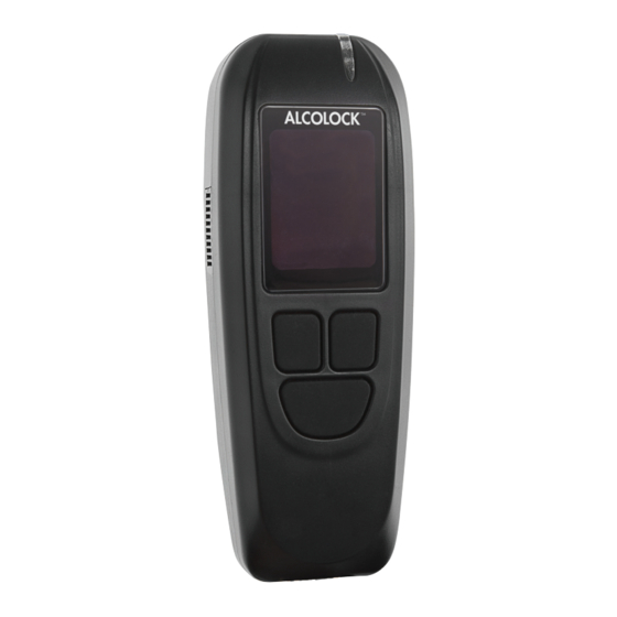
- Page 3 ALCOLOCK LR HANDSET COMPONENTS Mouthpiece Indicator light Air vent Sampling port Display Navigation buttons* *The navigation buttons permit the selection of Cable input options shown on HDMI port SIDE VIEW the display. Press the left, right, or bottom button to select...
-
Page 4: Table Of Contents
TABLE OF CONTENTS 1.0 ALCOLOCK LR max alcohol interlock product profile The ALCOLOCK LR max device installation manual How to read this manual Other required manuals Parts and equipment supplied by ACS (the service provider) Tools and equipment supplied by the service centre (service facility) Power tools... - Page 5 Tampering 23.1 Signs of tampering 23.2 Examples of tampering – before and after 23.3 Signs of tampering -- event log 23.4 Tamper Report Procedure Appendixes Appendix 1: Tamper report Appendix 2: Glossary Appendix 3: LR max circuit diagram (low-current vehicles)
-
Page 6: Alcolock Lr Max Alcohol Interlock Product Profile
THE ALCOLOCK LR MAX DEVICE INSTALLATION MANUAL This manual contains procedures for the installation, monitoring and removal of the ALCOLOCK LR max device, as well as wiring diagrams and a glossary of terms. ATTENTION! •... -
Page 7: How To Read This Manual
Read entire manual before operating the Automotive Diagnostic Tool HOW TO READ THIS MANUAL • For installation of the ALCOLOCK LR max device, read sections 5.0 to 20.0 of this manual in the order provided • For wiring diagrams (with and without the external relay), refer to Appendices 3 and 4 of this manual •... -
Page 8: Parts And Equipment Supplied By Acs (The Service Provider)
This section lists parts supplied by ACS, which are required by the Service Centre for the alcohol interlock program; including installation, monitoring, calibration and removal of the ALCOLOCK LR max device. Contact ACS to order the following parts (for contact information, refer to acs-corp.com). - Page 9 Accessories and consumable items for alcohol interlock program: PART # PART DESCRIPTION 79-008953 External relay (12V) Additional relay (high-current starter circuit) 79-008961 External relay (24V) Additional relay (high-current starter circuit) 94-001960 Lamp flasher module Visual alarm, vehicle indicators (12V negative) 94-001961 Lamp flasher module Visual alarm, vehicle indicators (12V positive) 79-000300...
-
Page 10: Tools And Equipment Supplied By The Service Centre (Service Facility)
TOOLS AND EQUIPMENT SUPPLIED BY THE SERVICE CENTRE (SERVICE FACILITY) This section lists parts supplied by the Service Centre, which are required for the installation, monitoring and removal of the ALCOLOCK LR max device. POWER TOOLS • Portable reversible battery operated drill with bits •... -
Page 11: Installation Overview
INSTALLATION OVERVIEW To install the ALCOLOCK LR max device, complete the following steps in the order provided in this manual. • Inspecting the vehicle electrical system • Mounting the ECU, alarm horn, and (if required) alarm flasher • (Skip if using OBD-II) Locating the tach signal (using DTS, if applicable) •... -
Page 12: Inspecting The Vehicle Charging System
Fasten the ECU to the mounting position with the supplied tie wraps. NOTE: Always use existing hardware and holes to minimize vehicle modification. Ensure that the connection is tight and secure. On the back of the antenna, there is double-sided tape. Peel the plastic backing off the tape and affix the antenna to the inside of the windshield. ALCOLOCK LR max... -
Page 13: Mounting The Alarm Horn
10.0 MOUNTING THE ALARM HORN The alarm horn (79-000916) is installed under the hood and is wired to the alcohol interlock ECU cable. It is programmed to activate when the client has failed to respond to a retest request past the set limit. ATTENTION! The alarm horn is intended for installation on vehicles with +12 volt electrical systems only. -
Page 14: Mounting The Retest Alarm (For Hearing- Impaired)
Connect the ECU cable (13-001151) only after doing the following: • Inspecting the vehicle electrical system • Mounting the ECU, alarm horn, and alarm flasher (if required) • Locating the tach signal (if OBD-II is not being used) This section will provide an overview and steps for the connection of ECU cable, alarm horn and (if required) the alarm flasher. ALCOLOCK LR max... -
Page 15: Ecu Cable-Wire Summary
Do not solder or apply heat shrinks or tamper proof labels until all wires have been attached, and post-installation testing has been performed • The ALCOLOCK LR max alcohol interlock is a low current device. Use a supplied external relay on vehicles with high-current starter circuits (above 2 amps) •... -
Page 16: Ecu Wire-Connection Steps
(e.g., start and accessories). Expose 1/2” of the continuous (un-switched) source wire. Twist the end of ECU wire 12 (Red) around the continuous (un-switched) source wire. NOTE: Twist the wire as follows: ALCOLOCK LR max... - Page 17 ATTENTION! • The ALCOLOCK LR max alcohol interlock is a low current device. Use an external relay on vehicles with high-current starter circuits (above 2 amps) • Refer to Appendix 4 at the back of this manual for the wiring diagram that includes the external relay 13.
-
Page 18: Alarm Horn Wire Connection Steps
NOTE: The ground connection should look as follows: (This illustration shows a – sealed connection do not seal until the installation is verified. Refer to section 20.0 of this manual.) Connect ECU wire 19 (Brown) to ECU wire 12 (Red). Connect ECU wire 20 (Orange) to the red (positive) alarm flasher wire. ALCOLOCK LR max... -
Page 19: Retest Alarm Wire-Connection Step (Install For Hearing-Impaired)
14.5 RETEST ALARM WIRE-CONNECTION STEP (INSTALL FOR HEARING-IMPAIRED) NOTE: • Skip this section if a retest alarm (for hearing-impaired drivers) is not required • Section 12.0 provides instructions for mounting the retest alarm (alarm flasher) and feeding the wires to the ECU cable location Fasten a ring terminal (21-000022) to the black (ground) retest alarm wire. -
Page 20: Obd-Ii Wire-Connection Steps
Plug the vehicle OBD-II connector (detached in the previous step) into the male connector of the OBD-II cable assembly. Mount the female connector of the OBD-II cable assembly in place of the connector detached in step two. ALCOLOCK LR max... -
Page 21: Attaching The Hs And Ecu
Locate the white, 5-pin connector from the ECU cable and place the black heat shrink (79-000262) over it. Do not seal heat shrink until instructed. Connect the 5-pin white connector from the ECU cable to the 5-pin port of the OBD-II cable assembly (on the electrical box). -
Page 22: Hs Install Procedure And Ite Install Transaction
HS INSTALL PROCEDURE AND ITE INSTALL TRANSACTION After the ALCOLOCK LR max device has been connected to the vehicle, perform the HS install procedure by following the steps that appear on the HS screen. The purpose of the HS install procedure is to activate the device and test device functions. -
Page 23: Performing The Hs Install Procedure
USING HANDSET BUTTONS: HS screen options will appear at the bottom of the display (at the left, right or bottom-centre). Press the left, right or bottom navigation button to select a corresponding screen-command option. NOTE: • To access the HS install procedure, a daily service code is required – obtained from ITE •... - Page 24 Correct to re-enter the service code, or press SERVICE CODE Cancel to return to Main Menu. 3729 Cancel Accept Correct In the SERVICE menu, press Prev or Next to scroll to Install, then press Select. Service Install Prev Next Select Wait is briefly displayed as the install procedure loads. Wait ALCOLOCK LR max...
- Page 25 NOTE: INSTALL will display at the top of the screen during the HS install procedure. INSTALL HANDSET LED & Buzzer HANDSET LED & Buzzer is displayed. The HS LED light flashes from red to green to amber. On each flash, the HS beeps with a descending pitch. After this sequence, Exit OK appears.
- Page 26 Before starting the ignition, ensure that the vehicle is in the park / neutral position, with parking brake engaged, to prevent the vehicle from moving • Leaving the vehicle engine on for too long will cause the vehicle alarm horn to sound ALCOLOCK LR max...
-
Page 27: Obd-Ii Select
16.2 OBD-II SELECT OBD SELECT is automatically displayed. NOTE: OBD SELECT • For conventional / non-hybrid vehicles, the ALCOLOCK LR OBD/TACH max device must obtain a tach (rpm) reading from under the hood. • Select For non-hybrid vehicles with OBD-II, a tach signal may be Exit obtained by connecting the ECU to vehicle OBD-II. -
Page 28: Obd / Tach
Idle Point – a preset rpm threshold value • Run Point – a preset rpm threshold value NOTE: The initial Idle Point and Run Point values may vary, depending on the vehicle. Check that the Idling rpm reading reflects the reading on the dashboard rpm gauge. ALCOLOCK LR max... - Page 29 If the Idling rpm reading is acceptable, press Set Tach to reset the rpm thresholds. INSTALL NOTE: After Set Tach is pressed, the Idling rpm reading (on TACH the first line) is used to reset the Idle Point and Run Point tach Idling 00960 Idle Point:...
-
Page 30: Obd Speed
Press OK to proceed. If the speed is correct, Turn Off Engine is displayed. INSTALL Turn Off Turn the key to the off position. Engine Cancel Skip section 16.2.3 and continue to section 16.3 to input the odometer reading. ALCOLOCK LR max... -
Page 31: No Obd
16.2.3 NO OBD NOTE: Read this section for non-hybrid vehicles where the tach was not obtained through OBD-II. After selecting the NO OBD option in section 16.2 “OBD Select”, TACH is displayed, along with the following: INSTALL • Idling – the vehicle engine rpm reading TACH Idling 00960... -
Page 32: Input Odometer Reading
After the tach or speed threshold has been set, Odometer is displayed. INSTALL ODOMETER Set the odometer value (press – or + to change a digit, 00000000 and press Select to move to the next digit). [–] Select ALCOLOCK LR max... -
Page 33: Performing An Ite Install Transaction
After entering the last digit value, press Select, INSTALL ODOMETER 00060202 Cancel SELECT Correct Then press ACCEPT. (Press Correct to reset the odometer value.) Continue to the next section. INSTALL ODOMETER 00060202 Cancel ACCEPT Correct 16.4 PERFORMING AN ITE INSTALL TRANSACTION After the odometer value has been accepted, Install Complete Connect to PC is displayed. -
Page 34: Post-Installation Testing
With the vehicle in park or neutral, turn on the vehicle engine for a short period. NOTE: Refer to the instruction manual for more information about using the ALCOLOCK LR max device. 18.0 ATTACHING THE SECURITY ENCLOSURE Attach the security enclosure only after doing the following: •... -
Page 35: Sealing Connections And Restoring The Vehicle
Attach the rear clip by aligning the grooves of the clip with the ridges of the ECU , and fitting the slots at the top of the clip over the HS and ECU cables The rear-clip screw hole lines up with the front-clip brass insert. Click the enclosure clips into place so that there are no gaps between the front and rear clips. -
Page 36: Hs Monitor Procedure, Ite Calibration And Monitor Transactions
If an alarm flasher or retest alarm was used, seal the connections with electrical tape and a tamper proof label. Reinstall all vehicle panels. Perform a final visual inspection. Ensure that the vehicle is returned to its original appearance. *YOU HAVE COMPLETED THE INSTALLATION OF THE ALCOLOCK LR max ALCOHOL INTERLOCK DEVICE* 20.0 HS MONITOR PROCEDURE, ITE CALIBRATION AND MONITOR TRANSACTIONS During routine monitoring appointments, perform the HS monitor procedure by following the steps that appear on the HS screen. -
Page 37: Performing The Hs Monitor Procedure
ATTENTION! • Complete the HS monitor procedure on the HS display before performing an the ITE calibration and monitor transactions • Before beginning the procedure ensure that there is sufficient ventilation for vehicle exhaust fumes. Failure to do so may cause injury •... - Page 38 In the SERVICE menu, press Prev or Next to scroll to Monitor, then press Select. SERVICE Monitor Prev Next Select Wait is briefly displayed as the monitor procedure loads. Wait NOTE: MONITOR will display at the top of the screen during the HS monitor procedure. ALCOLOCK LR max...
- Page 39 HANDSET LED & Buzzer is displayed. The HS LED light flashes from red to green to amber. On each flash, the MONITOR HS beeps with a descending pitch. After this sequence, OK appears. HANDSET LED & Buzzer If the test is successful, press OK. Exit NOTE: •...
- Page 40 Before starting the ignition, ensure that the vehicle is in the park / neutral position, with parking brake engaged, to prevent the vehicle from moving • Leaving the vehicle engine on for too long will cause the vehicle alarm horn to sound ALCOLOCK LR max...
-
Page 41: Obd-Ii Select
20.2 OBD-II SELECT OBD SELECT is automatically displayed. OBD SELECT NOTE: • For conventional / non-hybrid vehicles, the ALCOLOCK LR OBD/TACH max device must obtain a tach (rpm) reading from under the hood. • Select For non-hybrid vehicles with OBD-II, a tach signal may be... -
Page 42: Obd / Tach
Idle Point – a preset rpm threshold value • Run Point – a preset rpm threshold value NOTE: The initial Idle Point and Run Point values may vary, depending on the vehicle. Check that the Idling rpm reading reflects the reading on the dashboard rpm gauge. ALCOLOCK LR max... - Page 43 If the Idling rpm reading is acceptable, press Set Tach to reset the rpm thresholds. MONITOR NOTE: After Set Tach is pressed, the Idling rpm reading (on TACH the first line) is used to reset the Idle Point and Run Point tach Idling 00960 Idle Point:...
-
Page 44: Obd Speed
If the speed is correct, Turn Off Engine is displayed. MONITOR Turn Off Turn the key to the off position. (Press Cancel to return Engine to the Monitor menu.) Cancel Skip section 21.2.3 and continue to section 15.3 to input the odometer reading. ALCOLOCK LR max... -
Page 45: No Obd
20.2.3 NO OBD NOTE: Read this section for non-hybrid vehicles where the tach was not obtained through OBD-II. After selecting the NO OBD option in section 21.2 “OBD Select”, TACH is displayed, along with the following: MONITOR • Idling – the vehicle engine rpm reading TACH Idling 00960... -
Page 46: Input Odometer Reading
After the tach or speed threshold has been set, Odometer is displayed. MONITOR ODOMETER 00000000 Set the odometer value (press – or + to change a digit, and press Select to move to the next digit). [–] Select ALCOLOCK LR max... -
Page 47: Performing The Ite Calibration And Monitor Transactions
After entering the last digit value, press Select, then press ACCEPT. (Press Correct to reset the odometer MONITOR value.) Continue to the next section. ODOMETER 00060202 Cancel ACCEPT Correct 20.4 PERFORMING THE ITE CALIBRATION AND MONITOR TRANSACTIONS After the odometer value has been accepted, Monitor Complete Connect to PC is displayed. -
Page 48: Device Removal Overview
USING HANDSET BUTTONS: HS screen options will appear at the bottom of the display (at the left, right or bottom-centre). Press the left, right or bottom navigation button to select a corresponding screen-command option. ALCOLOCK LR max... -
Page 49: Performing The Hs Removal Procedure
NOTE: • To access the HS removal procedure, a daily service code is required – obtained from ITE • To exit the procedure at any time, press and hold the bottom button to select Exit • Remaining in any screen for 5 minutes will exit the procedure 21.2 PERFORMING THE HS REMOVAL PROCEDURE Press any navigation button to power up the device. - Page 50 Restart the procedure and if the problem persists, (1) check the HS cable (2) contact ACS. ECU Speaker is displayed. The HS LED light is off. The ECU beeps and the pitch descends for three beeps. After REMOVAL this sequence, OK is displayed. Speaker Exit ALCOLOCK LR max...
- Page 51 If the test is successful, press OK. NOTE: • If the ECU does not beep, or OK is not displayed, press and hold the bottom button to exit the procedure. • Restart the procedure and if the problem persists, (1) check the ECU cable connections (2) contact ACS.
-
Page 52: Obd-Ii Select
21.3 OBD-II SELECT OBD SELECT is automatically displayed. OBD SELECT NOTE: • For conventional / non-hybrid vehicles, the ALCOLOCK LR OBD/TACH max device must obtain a tach (rpm) reading from under the hood. • Select For non-hybrid vehicles with OBD-II, a tach signal may be Exit obtained by connecting the ECU to vehicle OBD-II. - Page 53 Press Select to scroll to one of the 3 following options: OBD / TACH OBD SELECT For non-hybrid vehicles connected to OBD-II. OBD/TACH Select Exit OBD / SPEED OBD SELECT For hybrid vehicles connected to OBD-II. OBD/SPEED Select Exit NO OBD OBD SELECT For vehicles not connected to OBD-II, and instead connected to a direct tach source under the hood.
-
Page 54: Obd / Tach
Idling – the vehicle engine rpm reading • TACH Idle Point – reset to 0.5 x the Idling engine rpm • Idling 00960 Run Point – reset to 1.5 x the Idling engine rpm Idle Point: 00480 Run Point: 01440 Set Tach Exit ALCOLOCK LR max... - Page 55 Next is displayed at the bottom-left of the screen. REMOVAL TACH If the tach thresholds are correct, press Next (otherwise Idling 00960 press Set Tach until a correct tach threshold is obtained). Idle Point: 00480 Run Point: 01440 Next Set Tach Exit After Next is pressed, ACCELERATE is displayed, along with the following:...
-
Page 56: Obd Speed
• If the problem continues, (1) obtain the tach signal using a digital tach sensor (DTS) (2) contact ACS. • Idle Point – a preset rpm threshold value • Run Point – a preset rpm threshold value ALCOLOCK LR max... - Page 57 NOTE: The initial Idle Point and Run Point values may vary, depending on the vehicle. Check that the Idling rpm reading reflects the reading on the dashboard rpm gauge. If the Idling rpm reading is acceptable, press Set Tach to reset the rpm thresholds. REMOVAL NOTE: After Set Tach is pressed, the Idling rpm reading (on TACH the first line) is used to reset the Idle Point and Run Point Idling...
-
Page 58: Input Odometer Reading
Cancel ACCEPT Correct 21.5 PERFORMING AN ITE REMOVAL TRANSACTION After the odometer value has been accepted, Removal Complete Connect to PC is displayed. REMOVAL Removal Complete Disconnect the HS from the HS cable. Connect to PC Exit ALCOLOCK LR max... -
Page 59: Removing Ecu And Restoring The Vehicle
Connect the HS to the UCS or DS and perform an ITE removal transaction. NOTE: For instructions by completing ITE transactions and connecting Download Station or UCS, see the following manuals: • ITE application manual • UCS instruction manual • Download Station Manual When the ITE transaction is complete, connect the HS back to the ECU. - Page 60 13. Ensure that all the wires that were cut and reconnected are soldered together, then resealed with tape and heat shrinks. 14. Solder all connections. Shrink-wrap, tape and neatly tie-strap them. 15. Reinstall all vehicle panels. 16. Perform a final inspection. Ensure that vehicle is returned to its original appearance. ALCOLOCK LR max...
-
Page 61: Recycling The Alcolock Lr Max Device
22.0 RECYCLING THE ALCOLOCK LR MAX DEVICE Following the removal, devices (ECU, HS, or both) that are functioning correctly will remain at the Service Centre. Devices in need of repair, or at the end of their service life, must be returned to ACS. - Page 62 Tamper resistent label over vehicle grounding: Tamper seal over security enclosure (front clip): HS screw plugs (x4): ALCOLOCK LR max...
-
Page 63: Signs Of Tampering -- Event Log
ATTENTION! • Any signs of tampering must be detailed in the Tamper Report (refer to Appendix 1 in this manual) • Tampering is not limited to these areas. Inspect the entire ALCOLOCK LR max device EVENT DESCRIPTION WHERE TO INSPECT... -
Page 64: Tamper Report Procedure
The service technician must resolve any matters surrounding the functioning of the ALCOLOCK LR max device. NOTE: If the event was not caused by a mechanic, it must be documented in the occurrence report. -
Page 65: Appendixes
Tamper Type: Date of Tamper: Time of Tamper: Comments: Violation Type Indicate all Violations Power Off/ Power On Recall Picture Start Violation Picture Other Picture Other Alcohol Countermeasure Systems FAX (1) COPY OF THIS ALCOLOCK @________________ FORM TO: INSTALLATION MANUAL... -
Page 66: Appendix 2: Glossary
(HS or ECU): Performed on ITE when an installed HS or ECU requires replacement. handset (HS): Part of the ALCOLOCK LR max device that is used to conduct breath alcohol tests and communicate with the driver. HDMI (high-definition multimedia interface): The ALCOLOCK LR max device HS and ECU are each equipped with an HDMI receptacle. - Page 67 INTERTRACK Enterprise (ITE): A proprietary computer-software application, and its suite of applications, developed by ACS and provided as a service over the internet for use by Service Providers, Service Centres, and others authorized by ACS for the delivery of Program Services – including any upgrades thereto. installation appointment: The initial Service Centre appointment for reviewing client status, physically inspecting the vehicle, installing the alcohol interlock, activating and testing alcohol interlock functions, and providing client training.
- Page 68 The tach signal (rpm) value at which the vehicle engine is on with the accelerator pedal pressed. During the HS install, monitor and removal procedures, the ALCOLOCK LR max device sets the vehicle run threshold at 1.5 x idling engine rpm.
-
Page 69: Appendix 3: Lr Max Circuit Diagram (Low-Current Vehicles)
APPENDIX 3: LR MAX CIRCUIT DIAGRAM (LOW-CURRENT VEHICLES) INSTALLATION MANUAL... - Page 72 INM-ENG-60-000740-A © 2015...
Need help?
Do you have a question about the LR max and is the answer not in the manual?
Questions and answers