Table of Contents
Advertisement
Quick Links
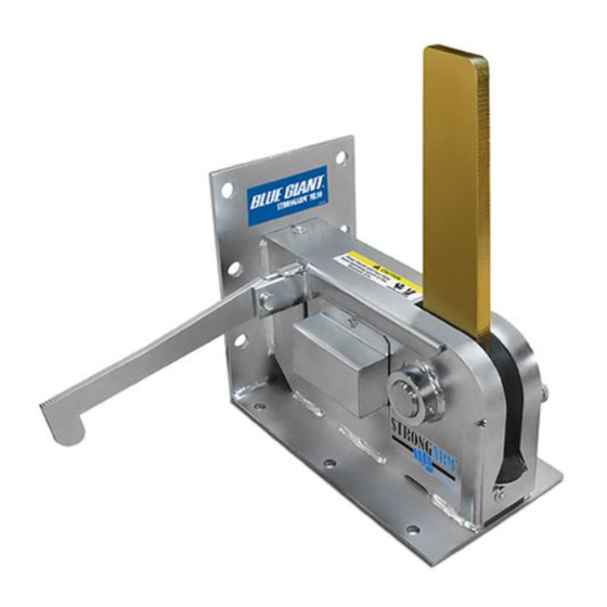
ACTUAL PRODUCT MAY NOT APPEAR EXACTLY AS SHOWN
WARNING
Do not operate or service this product unless you have
read and fully understand the entire contents of this
manual. Failure to do so may result in property damage,
bodily injury or death.
STARTING FROM AUGUST, 2013 / SERIAL # 376630
OWNER'S MANUAL
STRONGARM™ ML10 VEHICLE RESTRAINT
ISSUE DATE: SEPTEMBER 29, 2014 REV.0 (PART # 038-538E)
Advertisement
Table of Contents

Related Manuals for Blue Giant STRONGARM ML10

Summary of Contents for Blue Giant STRONGARM ML10
- Page 1 OWNER’S MANUAL STRONGARM™ ML10 VEHICLE RESTRAINT ACTUAL PRODUCT MAY NOT APPEAR EXACTLY AS SHOWN WARNING Do not operate or service this product unless you have read and fully understand the entire contents of this manual. Failure to do so may result in property damage, bodily injury or death.
-
Page 2: Table Of Contents
STRONGARM™ ML10 VEHICLE RESTRAINT—OWNER’S MANUAL TABLE OF CONTENTS ABOUT THE STRONGARM™ ML10 WITH OPTIONAL TLC24 CONTROLS OWNER’S PURCHASE RECORD INTRODUCTION WARRANTY INFORMATION EXCLUSION OF LIABILITY MANUFACTURER’S NOTE OWNER’S RESPONSIBILITY SAFETY MESSAGE COLOR IDENTIFICATION OPERATIONAL SAFETY WARNINGS LOCKOUT / TAGOUT PROCEDURE AND RULES OPERATING INSTRUCTIONS - STANDALONE STRONGARM™... -
Page 3: About The Strongarm™ Ml10 With Optional Tlc24 Controls
STRONGARM™ ML10 VEHICLE RESTRAINT—OWNER’S MANUAL 1.0 ABOUT THE STRONGARM™ ML10 WITH OPTIONAL TLC24 CONTROLS The StrongArm™ ML10 Mechanical Vehicle Restraint is a high-performance yet low-cost solution for loading docks worldwide. With a vertical restraining range of 11" to 26" (279 mm to 660 mm) above ground and horizontal reach of 13" (330 mm), the ML10 is compatible with virtually all modern trucks and trailers, even those with air-ride suspension systems. -
Page 4: Introduction
2.1 WARRANTY INFORMATION The following is a quick reference to important procedures that Thank you for purchasing Blue Giant products. We appreciate your must be followed while using the Vehicle Restraint System. It is business, and are confident that our product will serve you for not intended to cover, or suggest that it does cover, all procedures many years to come. -
Page 5: Owner's Responsibility
10. If, at the request of the owner, Blue Giant does not supply effectively. all or some of the dock equipment power unit and/or control station components, the owner shall assume responsibility for 3. -
Page 6: Safety Message Color Identification
STRONGARM™ ML10 VEHICLE RESTRAINT—OWNER’S MANUAL 3.0 SAFETY MESSAGE COLOR IDENTIFICATION This manual includes color-coded safety messages that clarify instructions and specify areas where potential hazard exists. To prevent the possibility of equipment damage and serious injury or death, please observe strictly the instructions and warnings contained in the messages. -
Page 7: Lockout / Tagout Procedure And Rules
The machine or equipment power supply shall be locked in the OFF position or disconnected from the energy source. Blue Giant® strongly recommends that only OSHA-approved lockout devices and procedures be utilized. The energy isolating device must bear a prominent warning tag indicating that work is being done on the equipment and the name of the authorized employee responsible for the lockout. -
Page 8: Operating Instructions - Standalone Strongarm™ Ml10
(ICC bar), restricting forward movement caused by vehicle creep or unscheduled departure. It is mechanically engaged and disengaged using a control rod (782-371). For added safety, Blue Giant recommends the use Vehicle ICC Bar of a lights communication package (TLC24-A or TLC24-M) in Dock Face conjunction with the ML10. -
Page 9: Prior To Use: Equipment In Home Position
After the truck is correctly parked, chock wheels securely. 5.4 ENGAGING RESTRAINT Activate the ML10 by using the control rod (Blue Giant part # 782-371) to press down on the engagement arm until the restraint arm is in the fully vertical locked position, which now holds the ICC bar in place. -
Page 10: Releasing The Restraint Arm
After loading / unloading has been completed and the dock leveler is safely parked, release the restraint arm by pulling up on it quickly and firmly using the control rod (Blue Giant part # 782-371). The arm will return to the parked position. -
Page 11: Planned Maintenance (Pm) Check List - Vehicle Restraint - Based On Cycles
STRONGARM™ ML10 VEHICLE RESTRAINT—OWNER’S MANUAL 6.0 PLANNED MAINTENANCE (PM) CHECK LIST – VEHICLE RESTRAINT – BASED ON CYCLES INSTRUCTIONS FOR USE: Photocopy this page and indicate “OK for USE” with a check mark in the appropriate box of each inspection point. EVERY DAY: ... -
Page 12: Recommended Spare Parts
STRONGARM™ ML10 VEHICLE RESTRAINT—OWNER’S MANUAL 7.0 RECOMMENDED SPARE PARTS 7.1 STANDARD OPERATIONAL COMPONENTS RSP FOR ML10 – STD OPERATIONAL COMPONENTS RSP FOR ML10 – STD OPERATIONAL COMPONENTS ITEM ITEM PART NO. DESCRIPTION PART NO. DESCRIPTION REQ’D REQ’D 782-371 Control Rod 522-5005 Arm, Pivot Shaft Assembly 017-012... -
Page 13: Protective Components
STRONGARM™ ML10 VEHICLE RESTRAINT—OWNER’S MANUAL 7.2 PROTECTIVE COMPONENTS RSP FOR ML10 – PROTECTIVE COMPONENTS ITEM NO. PART NO. DESCRIPTION REQ’D 52-011187 Top Cover 7.3 TLC24 COMPONENTS (OPTIONAL) RSP FOR TLC24 COMPONENTS (OPTIONAL) RSP FOR TLC24 ITEM ITEM PART NO. DESCRIPTION PART NO. -
Page 14: Decal Identification And Location
R e s t r a i n t 038-240 CAUTION Keep Hands and Feet away from operating space of the Restraint Arm. CRUSH HAZARD 038-243E BLUE GIANT EQUIPMENT CORPORATION www.BlueGiant.com MADE IN CANADA HECHO EN CANADA MODEL/ ML10 MODELO SERIAL NO./... -
Page 15: Equipment Component Illustrations
STRONGARM™ ML10 VEHICLE RESTRAINT—OWNER’S MANUAL 9.0 EQUIPMENT COMPONENT ILLUSTRATIONS OPERATING INSTRUCTIONS Only for the ML10 and TLC24-A (Automatic) or TLC24-M (Manual) 9.1 COMPONENTS AS SHIPPED CHECK LIST ENGAGE RESTRAINT Activate the ML10 by using the control rod to OUTSIDE TRAFFIC INSIDE COMMUNICATION LIGHT STATUS LIGHTS &... -
Page 16: Mechanical Assembly - 52-011130
STRONGARM™ ML10 VEHICLE RESTRAINT—OWNER’S MANUAL 9.2 MECHANICAL ASSEMBLY - 52-011130 OPTIONAL: AUTOMATIC LIGHT PACKAGE NOTE PART NO. DESCRIPTION 52-011131 Automatic light package includes parts highlighted ISSUE DATE: SEPTEMBER 29, 2014 REV.0 (PART # 038-538E) -
Page 17: General Dimensions
STRONGARM™ ML10 VEHICLE RESTRAINT—OWNER’S MANUAL 9.2 MECHANICAL ASSEMBLY - 52-011130 ITEM QTY. PART NO. DESCRIPTION ITEM PART NO. DESCRIPTION 52-011160 Body Weldment 013-025 Cotter Pin 3/16" x 1 ½" (38mm) 52-012731 Restraint Arm 26" (660mm) 013-018 Cotter Pin 3/32" x 1" (25mm) 522-5005 Shaft Arm Pin 011-020... -
Page 18: Operating Instructions - Strongarm™ Ml10 With Tlc24 Controls (Automatic & Manual)
STRONGARM™ ML10 VEHICLE RESTRAINT—OWNER’S MANUAL 10.0 OPERATING INSTRUCTIONS - STRONGARM™ ML10 WITH TLC24 CONTROLS (AUTOMATIC & MANUAL) STANDARD OPERATION PROCEDURES The TLC24-M has interior and exterior LED light signals (red / green) that are manually controlled to communicate safety conditions to both dock workers and truck drivers. -
Page 19: Engaging Restraint
STRONGARM™ ML10 VEHICLE RESTRAINT—OWNER’S MANUAL 10.3 ENGAGING RESTRAINT Activate the ML10 by using the control rod to press down on TLC24-M: Turn the key switch to the 'Interlocked' position (green the engagement arm until the restraint arm is in the fully vertical LED light). -
Page 20: Manual Override Mode (Tlc24-A)
STRONGARM™ ML10 VEHICLE RESTRAINT—OWNER’S MANUAL OVERRIDE FEATURES 10.5 MANUAL OVERRIDE MODE (TLC24-A) Situations may arise that require the TLC24-A to be operated Under these circumstances, a supervisor or designated authority manually. For example: may operate the TLC24-A in manual override mode by using the • The truck ICC bar is bent, damaged, or missing key switch to operate the lights manually. -
Page 21: Tlc24 Controls
STRONGARM™ ML10 VEHICLE RESTRAINT—OWNER’S MANUAL 10.6 TLC24 CONTROLS ‡ OPTIONAL ‡ TLC24-A AUTOMATIC TLC24-M MANUAL COMPLETE CONTROL STATION ASSEMBLY ITEM # 1 COMPLETE CONTROL STATION ASSEMBLY ITEM # 1 (Example: TLC24A1115F) (Example: TLC24A1115F) ITEM PART NO. DESCRIPTION ASSY PART # ITEM PART NO. -
Page 22: Operating Instructions - Strongarm™ Ml10 With Blue Genius™ Controls
STRONGARM™ ML10 VEHICLE RESTRAINT—OWNER’S MANUAL 11.0 OPERATING INSTRUCTIONS - STRONGARM™ ML10 WITH BLUE GENIUS™ CONTROLS 11.1 TRAILER AT BAY The truck reverses into position against the dock leveler bumpers. is RED. Chock the wheels and release the air from the air ride The outside traffic light is GREEN and the control station light suspension system (if applicable). -
Page 23: Releasing The Restraint Arm
STRONGARM™ ML10 VEHICLE RESTRAINT—OWNER’S MANUAL 11.3 RELEASING THE RESTRAINT ARM NOTE: If the ICC bar is applying pressure to the restraint arm, it may be necessary to have the driver back up the vehicle before After loading / unloading has been completed and the dock releasing the arm. -
Page 24: Blue Genius™ Controls
STRONGARM™ ML10 VEHICLE RESTRAINT—OWNER’S MANUAL 11.5 BLUE GENIUS™ CONTROLS Wiring Diagram Enclosed Fuse Holder 3 Fuse Holder 1 Fuse Holder 2 ITEM PART NO. DESCRIPTION COMPLETE CONTROL STATION ASSEMBLY - ITEM 1 (Example BGGM01115F) 026-G030 Ribbon Cable ITEM SINGLE PHASE ◊... -
Page 25: Exterior Traffic Light / Mirror Image Sign
STRONGARM™ ML10 VEHICLE RESTRAINT—OWNER’S MANUAL 12.0 EXTERIOR TRAFFIC LIGHT / MIRROR IMAGE SIGN Slim-build LED traffic lights and mirror image driver warning sign improve loading dock safety. ¼" (6.35 mm) ½" 5" (127 mm) (12.7 mm) 11.875" 1/2" (12.7 mm) 4"... -
Page 26: Vehicle Restraint Troubleshooting
STRONGARM™ ML10 VEHICLE RESTRAINT—OWNER’S MANUAL 13.0 VEHICLE RESTRAINT TROUBLESHOOTING WARNING Do not attempt to install, make repairs or adjustments. Only a trained and authorized service technician should perform the installation process. Contact your local dealer or distributor for assistance. PROBLEM PROBLEM CAUSE Damaged actuating arm or linkage. - Page 27 STRONGARM™ ML10 VEHICLE RESTRAINT—OWNER’S MANUAL 13.0 VEHICLE RESTRAINT TROUBLESHOOTING CONT'D WARNING Do not attempt to install, make repairs or adjustments. Only a trained and authorized service technician should perform the installation process. Contact your local dealer or distributor for assistance. PROBLEM PROBLEM CAUSE Faulty wiring or connections.
-
Page 28: Wiring Diagrams
STRONGARM™ ML10 VEHICLE RESTRAINT—OWNER’S MANUAL 14.1 WIRING DIAGRAM—TLC24-A 115V AND 230V SINGLE PHASE (AUTOMATIC) ISSUE DATE: SEPTEMBER 29, 2014 REV.0 (PART # 038-538E) -
Page 29: Wiring Diagram-Tlc24-M 115V And 230V Single Phase
STRONGARM™ ML10 VEHICLE RESTRAINT—OWNER’S MANUAL 14.2 WIRING DIAGRAM—TLC24-M 115V AND 230V SINGLE PHASE (MANUAL) ISSUE DATE: SEPTEMBER 29, 2014 REV.0 (PART # 038-538E) -
Page 30: Wiring Diagram-Blue Genius™ 115V Single Phase
STRONGARM™ ML10 VEHICLE RESTRAINT—OWNER’S MANUAL 14.3 WIRING DIAGRAM—BLUE GENIUS™ 115V SINGLE PHASE ISSUE DATE: SEPTEMBER 29, 2014 REV.0 (PART # 038-538E) - Page 31 STRONGARM™ ML10 VEHICLE RESTRAINT—OWNER’S MANUAL NOTES ISSUE DATE: SEPTEMBER 29, 2014 REV.0 (PART # 038-538E)
- Page 32 Corporate 85 Heart Lake Road South USA 6350 Burnt Poplar Road Brampton, ON, Canada L6W 3K2 Greensboro, NC 27409 t 905.457.3900 f 905.457.2313 www.BlueGiant.com If calling within North America: t 1.800.668.7078 f 1.888.378.5781 © Copyright Blue Giant Equipment Corporation 2014...
Need help?
Do you have a question about the STRONGARM ML10 and is the answer not in the manual?
Questions and answers