Table of Contents
Advertisement
Quick Links
TriggerTrac
Single Lane Version
Order and Installation Manual
For models from June 2019 onwards
Rugged Interactive
Unit 1, Callywith Court
Callywith Industrial Estate, Bodmin
Cornwall, UK
PL231 2RQ
+44 (0) 1726 981 123
www.rugged-interactive.co.uk
hello@rugged-interactive.co.uk
Updated 20/01/2021
© Rugged Interactive
2021
Advertisement
Table of Contents

Related Manuals for Rugged Interactive TriggerTrac


Summary of Contents for Rugged Interactive TriggerTrac
- Page 1 Single Lane Version Order and Installation Manual For models from June 2019 onwards Rugged Interactive Unit 1, Callywith Court Callywith Industrial Estate, Bodmin Cornwall, UK PL231 2RQ +44 (0) 1726 981 123 www.rugged-interactive.co.uk hello@rugged-interactive.co.uk Updated 20/01/2021 © Rugged Interactive 2021...
-
Page 2: Table Of Contents
Section 3 – Installation 3.1 Parts List 3.2 Tools and Components List 3.3 Installation Overview 3.4 Detailed Installation Section 4 – How to Use Section 5 – Programs Guide TriggerTrac System Specifications TriggerTrac Installation Checklist Next Steps © Rugged Interactive 2021... -
Page 3: Section 1 - Ordering Process
Installation manual purpose and limitations This manual is intended to provide guidance only, the installation of the Rugged Interactive product will be under your control. You will be responsible for making sure, upon completion of the installation, it is safe to use. -
Page 4: Order And Installation Checklist
1.2 - Order and Installation Checklist ☐ Contact the Rugged Interactive sales team or a partner / distributor to begin the process. Confirm the invoice and delivery address along with date required (lead time is at least 5 weeks), ☐... -
Page 5: Ordering And Installation Timeline
A raceway timer for ninja runs and obstacle courses featuring LED lights and sounds along with a super accurate timer. The Single Lane TriggerTrac features a start button that begins the lane timer, race down the course as quickly as possible and press the finish panel, stopping the timer. -
Page 6: Getting Started
If further information is required, please get in touch and we will be able to provide further information and guidance. 1.6 - Place Order To begin the order process with Rugged Interactive: Email: Sales@rugged-interactive.co.uk Or call the Sales Office:... -
Page 7: Section 2 - Safety Guidelines
Tidy back loose cables that could become a tripping hazard. ▪ Ensure that the playing area is clear. ▪ Immediately inform Rugged Interactive for maintenance advice if you have concerns. Don’ts: ▪ Do not wear shoes with leather soles or high heels. -
Page 8: In Play Safety Guidelines
TriggerTrac Installation and Instruction Manual: Safety Guidelines 2.2 In Play Safety Guidelines Please ensure you read the following points before using the equipment: This activity can be great fun, but it can also be dangerous. There is a risk of serious injury if care is not taken when using the equipment. - Page 9 TriggerTrac Installation and Instruction Manual: Safety Guidelines Don’ts: ▪ Do not attempt to use any of the equipment without undertaking instruction / training carried out by an appropriate instructor. ▪ Do not participate if you are unwell or have any pre-existing medical conditions including heart, back, neck, bone and/or muscle conditions.
-
Page 10: Section 3 - Installation
+44 (0) 1726 981 123 www.rugged-interactive.co.uk hello@rugged-interactive.co.uk Section 3 - Installation 3.1 - Parts List Please check off the received parts for the installation and alert Rugged Interactive immediately if anything is missing. 1 x Finish target. ☐ 1 x Hub control box. -
Page 11: Tools And Components List
TriggerTrac Order and Installation Manual: Installation 3.2 - Tools and Components List Arrange the necessary tools and the team to install the product. Ladder. ☐ Jigsaw. ☐ Hole saw. ☐ Industrial vacuum cleaner. ☐ Dustpan and brush. ☐ SDS impact drill. -
Page 12: Installation Overview
3.3 - Installation Overview Below is an overview of the steps needed to install TriggerTrac. More detail for the process is provided in the following pages. Please read through ALL of this prior to beginning the installation and if you are in any doubt, contact Rugged Interactive. -
Page 13: Detailed Installation
IMPORTANT: Take anti-static precautions. ▪ Structure: TriggerTrac is supplied as 1 x start button and up to 1 x stop pressure panel (stop button) plus 1 x ▪ Hub display box and appropriate cables. The start button can be fitted in any orientation - onto an appropriately sized plinth or post, or onto a ▪... - Page 14 A waiting / spectating area positioned nearby is advised. ▪ A leaderboard to go with each unit is highly recommended. ▪ IF YOU ARE IN ANY DOUBT, CALL RUGGED INTERACTIVE DIRECTLY ON +44 (0) 1726 833 882. TriggerTrac – Section 3 - Installation © Rugged Interactive...
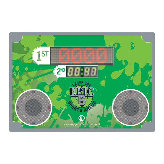
- Page 15 TriggerTrac Order and Installation Manual: Installation TriggerTrac Display / Score Box (HUB) Installation Notes: Fix HUB using any suitable self-tapping or wood screws into the surface material. The HUB can be ▪ recessed to be flush with the surface or affixed on top of the foam-backed vinyl if necessary.
- Page 16 TriggerTrac Order and Installation Manual: Installation Start Pod Installation The start button should be mounted onto a wall, plinth or post on the start line. It can be mounted via appropriate screws or with cable ties. Figure 3.4.1 shows a typical start button installation.
- Page 17 TriggerTrac Order and Installation Manual: Installation Pressure panels / stop button Installation Notes: Fit in line with the centre of the lane for the user. ▪ Note: Cables exit is at the rear of the pressure panel box. ▪ Mark out and cut the recesses for the pressure panel, the holes are to be 502 x 242mm each (+3 / - 0).
- Page 18 TriggerTrac Order and Installation Manual: Installation Connecting cables The Hub will have two hanging cables labelled for the start button and the stop pressure panel. Attach CAT5 cable from hanging cable to appropriate button. NOTE: Please use good practice when running data cables to and from products, targets and boxes.
- Page 19 TriggerTrac Order and Installation Manual: Installation Adjusting the Sensitivity Notes: • A small flat-bladed screwdriver is required. • Do not over tighten, this can damage the sensors, a maximum of a quarter turn in the appropriate direction should be made each time before retesting.
-
Page 20: Section 4 - How To Use
Hit the start button to start the time. TriggerTrac will sound a whistle. Players will race down either track to press their stop panel. When the player finishes and hits the stop panel, TriggerTrac will sound a ‘horn’. Their time will be shown on the display. -
Page 21: Section 5 - Programs Guide
Accurate timer featuring sounds and LEDs. Duration: Up to 10 minutes. NOTE: At any time, if TriggerTrac behaves unexpectedly during gameplay, wait for the unit to reset to its idle state or press and hold the start button for 5 seconds. TriggerTrac –... - Page 22 Approx. Shipment Details Fully Assembled Details Size (mm) Weight Size (mm) Weight TriggerTrac (1 start button, 1 finish 890 x 120 x 800 20 kg pressure pad, display / score box) Start button (single unit) 100 x 100 x 100...
- Page 23 TriggerTrac Order and Installation Manual: System Specifications Cut out sizes: Each target and the HUB/Score box will require a recess cut out of the wall for them to sit flush to the wall. Target Figure 1: Score box and target cut out size required for installation.
- Page 24 TriggerTrac Order and Installation Manual: System Specifications Mounting Points and Dimensions: Figure 2: Score box Mounting Points and Dimensions (Dimensions in mm) Figure 3: Target Mounting Points and Dimensions (Dimensions in mm) TriggerTrac - System Specifications © Rugged Interactive 2021...
- Page 25 Power Supply Specification for 5~9V) Features ‧ ‧ ‧ ‧ ‧ ‧ ‧ ‧ ‧ ‧ ‧ ℃ ‧ Ⅱ ‧ ‧ ‧ ‧ ...
- Page 26 Power Supply Specification SPECIFICATION PRODUCT GSM60B12-P1J SAFETY MODEL NO. GSM60B12 DC VOLTAGE Note.2 RATED CURRENT CURRENT RANGE 0 ~ 5A RATED POWER (max.) OUTPUT RIPPLE & NOISE (max.) 100mVp-p Note.3 ±3.0% VOLTAGE TOLERANCE Note.4 ±1.0% LINE REGULATION Note.5 ±3.0% LOAD REGULATION SETUP, RISE TIME 1000ms, 30ms / 230VAC 1500ms, 30ms / 115VAC at full load...
- Page 27 Power Supply Specification Derating Curve Static Characteristics (HORIZONTAL) ℃ AMBIENT TEMPERATURE ( ) INPUT VOLTAGE (VAC) 60Hz Mechanical Specification Case No. GSM60B Unit:mm ± U 2464 16AWG 1000 50mm for 5 ~ UL1185 16AWG 1500±50mm for 18 ~ 48V 31.5 POWER LED ±...
- Page 28 Bodmin, Cornwall, UK PL31 2RQ +44 (0) 1726 981 123 www.rugged-interactive.co.uk hello@rugged-interactive.co.uk TriggerTrac Installation Checklist Please complete this checklist after any installation: Check 1: Pre-power up checks. ☐ Mounted onto a wall of a construction capable of supporting its weight and gameplay.
- Page 29 +44 (0) 1726 833 882. * The volume control for TriggerTrac can be located on the reverse of the score box in the bottom left corner. The dial can be twisted clockwise to increase the volume and anti-clockwise to reduce it.
- Page 30 Next Steps Train team members Train your team members on how to use TriggerTrac, having knowledge of the gameplay will help them encourage users. Inspire them to cheer and celebrate with the customers when they achieve high scores. Maintenance General care and maintenance procedures for your Rugged Interactive product.
- Page 31 Congratulations! Congratulations on your new Rugged Interactive product! Your customers are going to love this, and it is a great addition to your venue! If there is anything we can assist with or if you would be interested in information about any other Rugged Interactive products, then please do not hesitate to get in contact.
Need help?
Do you have a question about the TriggerTrac and is the answer not in the manual?
Questions and answers