Table of Contents
Advertisement
Service Manual
Coffe machine
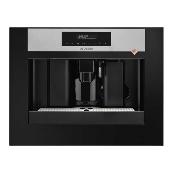
DE DIETRICH
DED700X
The manufacturer declines any responsibility or errors or omissions in this document. No part of the product can be reproduced, used
or copied without prior express written consent or unless this is allowed by a contractual clause.
Rev. 00
December 2007 Edition
Advertisement
Table of Contents

Subscribe to Our Youtube Channel
Related Manuals for DeDietrich DED700X


Summary of Contents for DeDietrich DED700X
- Page 1 Coffe machine DE DIETRICH DED700X The manufacturer declines any responsibility or errors or omissions in this document. No part of the product can be reproduced, used or copied without prior express written consent or unless this is allowed by a contractual clause.
- Page 2 CONTENTS OF THE DE DIETRICH MAINTENANCE MANUAL 1. Introduction Rev 00 from page 3 to page 4 1.1 Appropriate documents 1.2 Tools and equipment 1.3 Safety instructions 2. Technical information Rev 00 from page 5 to page 7 2.1 Internal components 2.2 Product technical data 3.
-
Page 3: Chapter 1 Introduction
CHAPTER 1 INTRODUCTION REV.00... - Page 4 1.1 Appropriate documents In order to make repairs the following documents must be available: Instruction notice specific to the model Technical documents specific to the model (diagrams, exploded views) 1.2 Tools and equipment The standard set of tools is needed plus the following special items : 1 special screwdriver with a T09 and T10 tip, Pozi Drive type screwdriver and a number 04 hex key.
-
Page 5: Chapter 2 Technical Information
CHAPTER 2 TECHNICAL INFORMATION REV.00... -
Page 6: Internal Components
2.1 Internal components... -
Page 7: Product Technical Data
2.2 Product technical data Power supply and consumption 230 V~; 50 Hz; 1250 W 120 V; 60 Hz; 1250W 100 V; 60 Hz; 1250 W Safety devices Coffee boiler 2 175°C safety thermostats – steam boiler 175°C thermostat and 229°C heat fuse Temperature control NTC Sensor Coffee resistor... -
Page 8: Chapter 3 Programming Diagnostics And Tests
CHAPTER 3 PROGRAMMING DIAGNOSTICS AND TESTS REV.00... - Page 9 3.1 Programming by the user Select product D On the main page press on the MENU key to access the Machine ready programming pages Press the OK key to go to ENERGY SAVING mode and reduce Energy savings power consumption. Press OK to restart the machine Rince The machine automatically eliminates water remaining in the Rince...
- Page 10 Total coffees This function is used to display the total number of coffees made Timer by the machine This function is used to save energy when the machine is not Timer used for long periods. This function is pre-set by the Clock manufacturer and automatically switches the machine to ENERGY SAVING mode when the set time has passed.
- Page 11 3.2 Diagnostics Mode SELECT FUNCTION MACHINE READY Auto-diagnostic To go to “diagnostics mode” turn on the machine is displayed. Within the first 5 seconds, press the 8-9-8-2 keys in order to display Programming Software and then press OK to display energy saving The programming menu is displayed.
- Page 12 Number of washing cycles Washing cycle counter Washing cycle status Status of the washing cycle De-scaling - Number Number of de-scaling cycles De-scaling status De-scaling status Phase code Machine status indicator Last maintenance day Last maintenance date (day) 1 - 31 Last maintenance month Last maintenance date (month) 1 - 12...
- Page 13 Test Mode Test mode is used to detect failures more easily and thus reduce the time needed to find them. SELECT FUNCTION MACHINE READY To enter TEST MODE Auto-diagnostic To go into “Test mode” switch on the machine, is displayed, within the next five seconds press the 10-11-10-11 keys in order.
- Page 14 Pressured up pump operation Key 1 + 7 To check that the pump is pressured up. (this is done to check for eventual leaks inside the machine) Steam boiler electric current Key 4 + 6 Check the electric current using an ammeter. During the temperature rise approx.
- Page 15 Outages displayed on the screen DISPLAYED OUTAGES CAUSES/SOLUTIONS Internal drip tray sensor GSI (water supply outage) Power Run water PURGE Check the water tank is correctly installed Replace upper / lower micro-switch Power GROUP BLOCKED Small geared motor Close the front panel Micro-switch Earthing of the machine disrupts the micro-switch CLOSE THE PANEL...
- Page 16 Checking micro-switches and sensors N° Description Activated Deactivated Notes Geared motor micro- Distributor in WORK Distributor not in switch WORK position WORK position Geared motor micro- Distributor in HOME Distributor not in switch HOME position HOME position Front command strip Command strip closed Command strip micro-switch...
-
Page 17: Chapter 4 Diagrams
CHAPTER 4 DIAGRAMS REV.00... -
Page 18: Cabling Diagram
4.1 Cabling diagram... - Page 19 Fuses FUSE 120 V 230V DESCRIPTION 02A/250V 01A/250V Coffee grinder safety Coffee boiler, grinder, main circuit 16A/125V 08A/250V and pump safety 16A/125V 08A/250V Steam boiler safety 02A/250V 02A/250V Main circuit safety...
-
Page 20: Hydraulics Diagram
4.2 Hydraulics diagram... -
Page 21: Chapter 5 Operating Logic
CHAPTER 5 OPERATING LOGIC REV.00... - Page 22 5.1 Hydraulics operating diagram n° Component Function Water tank Water supply Floater Water shortage detection Water filter Elimination of solid matter from the water Turbine Measures flow per impulse, sets quantities Water flow / pressure Pump (15 bar) Pressure safety valve Protects the circuit from over pressuring (opens at 17-19 bars) Heat exchanger / heater Heats for water, coffee, steam distribution.
- Page 23 5.2 The SBS system Distribution Process The SBS distribution system (see figure 2) can be set using a button and is used to change (by increase or decrease depending on the position of the button) the flow of water into the group for percolation. Thus the percolation time can be varied (extraction time) and, consequently, the intensity of the flavour, while keeping the coffee smooth.
- Page 25 Checking SBS valve operation To check that the SBS valve is working correctly, make a large coffee. While the coffee is preparing check the difference in distribution speed between the maximum position and the minimum position. The difference in speed is 2.5 times faster (therefore the difference is VERY obvious !!). LIGHT EXPRESSO SHORT...
-
Page 26: Aqua Prima
5.3 Aqua Prima Operating logic with “AQUA PRIMA” filter If the use of the “aqua prima” filter is selected from the user menu or the command strip, the system’s water measuring logic becomes the following : If the “aqua prima” function is active the electronics will count one turbine impulse every two revolutions. -
Page 28: Fitting And Removing Oetiker Clamps
5.4 Fitting and removing OETIKER clamps Fitting the clamp on the boiler BOILER The figure (1) shows where the clamp should be mounted on the boiler joint. To tighten the clamp use the appropriate pliers. Make sure it is sufficiently tight (A) and that it is in the right place (1) To remove the clamp proceed as illustrated (B) -
Page 29: Chapter 6 Fitting And Removing Components
CHAPTER 6 FITTING AND REMOVING COMPONENTS REV.00... - Page 30 6.1 Removing the upper panel and component support frame Remove the screws indicated Remove the upper panel as at the rear of the machine illustrated Cut the “B” clamp, remove the “A” connector and the “C” terminal connectors Remove the indicated screws on the LEFT and RIGHT sides...
- Page 31 Remove the screws shown on the front area and detach the steam pipe by removing the indicated clip Lift the component support frame Chassis Board...
- Page 32 Remove the indicated screws Cut the clamp Remove the cabling and then the upper board by lifting it...
-
Page 33: Removing The Coffee Grinder
6.2 Removing the coffee grinder Remove the screws indicated by an arrow (Note. when refitting the coffee grinder do not forget the two “2” that go around the motor “3”) Remove the coffee grinder When refitting the coffee grinder take care to correctly place the indicated joint... - Page 34 6.3 Removing the grinding wheels To remove the upper grinding wheel “A” (Unpack) turn it anti-clockwise as shown in the first picture using the “B” ring until the “C” tool is opposite the “D” aperture. (removing the upper grinding wheel) Once freed, the grinding wheel can be removed from its support.
- Page 35 (removing the lower grinding wheel) Clean out all coffee residue using a small flat screwdriver, compressed air or a vacuum cleaner. Turn the grinding wheel anti-clockwise while levering it using a small flat screwdriver as shown in the first picture. Once freed, the lower grinding wheel can be removed from its support.
- Page 36 6.4 Removing the coffee grinder motor Remove the screws of the grinder motor side-plate. Remove the sensor from the side-plate by pressing on the anchor tab. Remove the sensor from its casing in the side plate Disconnect the motor power cables. using a small screwdriver (as shown above) Remove the rubber cap from the motor side-plate.
- Page 37 If the crown is damaged, remove the cog wheel using a size 10 and a size 7 spanner to unscrew the fixing nut. Fit the new crown by placing it on the spindle gear and fix it by fitting the washer and fixing nut. Block the nut on the brass spindle axis using the size 7 and 10 spanners.
- Page 38 Evenly spread grease on the entire surface of the cog wheel. Apply grease to the teeth of the endless screw on the grinder motor shaft. Fit the motor side-plate as illustrated. Fit the fixing pins as illustrated and push them right into their housing.
- Page 39 6.5 Removing the boilers Steam boiler Remove screw “A” and the two “B” clamps, remove the two silicone meshed pipes. Remove the resistance protection cover “C” and disconnect the two “D” connectors. To remove the steam boiler, cut the two clamps and disconnect the two silicone pipes...
-
Page 40: Coffee Boiler
Coffee boiler Remove the screw as shown Remove the small cover and the indicated screws to free the boiler pivot To remove the coffee boiler remove the three screws as shown above. Disconnect the connector shown by the arrow Remove the boiler from its casing. - Page 41 Remove the fixing pin and disconnect the This picture shows the coffee boiler once removed from the casing. teflon pipe that connects the pump to the boiler by removing the clamp To replace the thermostats, remove the To remove the boiler from its base unscrew the indicated screw (this can also be done while indicated screw (A) the boiler is still in its casing)
- Page 42 6.6 Replacing the geared motor Remove the casing (A) by Remove the two screws and the removing the three screws. boiler pivot (B) Remove the protection cover (C) by removing the screws. Inside the area protected by the casing are : - the electric motor (A) with the transmission and synchronisation gears (B) and (C) for the distribution group;...
- Page 43 Fit the small motor and transmission shaft by placing the parts in their casing (L) Fit the gear (B), while making sure Fit the gear that couples with the that the printed arrow is included in transmission shaft. the opening that contains the pivot (P).
-
Page 44: Chapter 7 Exploded Views
CHAPTER 7 EXPLODED VIEWS REV.00... -
Page 45: Exploded View
7.1 Exploded view... - Page 47 Esp. E90046...
-
Page 48: List Of Recommended Spare Parts
7.2 List of recommended spare parts (Always use the latest version of the exploded view) N° Pos. Code Description Qty in % Planche 227370303 Distributor moving part 145853260 Gaco Joint 149501550 Distribution pipe 229186103 Distributor support 145854962 Joint 149206750 Push button mount 126839418 Push button spring 147895450... - Page 49 N° Qté Pos. Code Description Planche en % 11005060 Pivot set NM01.035 OR 0090-20 NM01.057 OR 0050-20 189428600 175° C Thermostat 11001522 NTC temperature sensor 11006731 230V boiler set 146520100 48x28 ceramic grinding wheel 11004354 Coffee grinder set NE05.038 Micro-switch 9121.042 Z 108 gear 9121.042...
-
Page 50: Chapter 8 Problems Causes
CHAPTER 8 PROBLEMS CAUSES SOLUTIONS REV.00... -
Page 51: Problems - Causes - Solutions
8.1 Problems - Causes - Solutions Problems Causes Solutions The machine will not power up The machine is not connected to a Have the mains connection checked power outlet The coffee is not hot enough The cups are cold Warm the cups with hot water The steam nozzle is obstructed The machine is not distributin g hot Remove the steam nozzle by pulling it downwards...
Need help?
Do you have a question about the DED700X and is the answer not in the manual?
Questions and answers