
Subscribe to Our Youtube Channel
Related Manuals for Macurco AimSafety PM400

Summary of Contents for Macurco AimSafety PM400
- Page 1 AimSafety™ PM Multi-Gas Personal Monitor User Instructions IMPORTANT: Keep these user instructions for reference.
-
Page 3: Table Of Contents
PM400 Multi-Gas Personal Monitor General Information ..............................4 Key Features ..............................4 Programmable options (PM Link) ........................4 Difference Between PM P and PM IR ....................... 5 1.3.1 Over Range Alarm Function ........................5 1.3.2 Catalytic Bead technology (PM P) Overview ..................5 1.3.3 Non-Dispersive Infra-Red (NDIR) technology (PM IR) Overview ............ - Page 4 PM400 Multi-Gas Personal Monitor WARNING Any unauthorized attempt to repair or modify the product, or any other cause of damage beyond the range of the intended use, including damage by fire, lightning, or other hazard, voids liability of the manufacturer. Activate this product only if sensor, visual, detection, and audible cover are clear from contaminants such as dirt and debris that could block the area where gas is to be detected.
-
Page 5: General Information
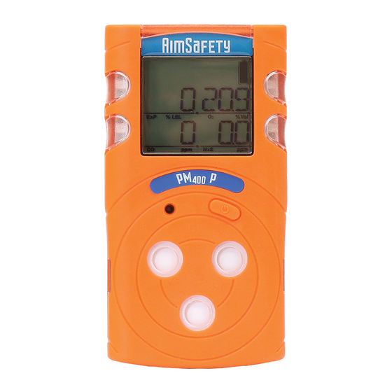
PM400 Multi-Gas Personal Monitor 1 General Information The innovative new AimSafety PM 4-gas portable monitor brings enhanced convenience and flexibility to gas detection in hazardous environments. The ergonomic PM diffusion gas monitor simultaneously detects up to four gases, including hydrogen sulfide (H S), carbon monoxide (CO), oxygen (O ) and combustibles (LEL). -
Page 6: Difference Between Pmp And Pm Ir
PM400 Multi-Gas Personal Monitor 1.3 Difference Between PM P and PM The PM P and the PM IR are identical units with one exception: The Combustible gas (LEL) sensors are different in each model. The PM P is equipped with a Catalytic Bead (Pellistor) sensor. The PM IR is equipped with a Non-Dispersive Infra-Red (NDIR) sensor. -
Page 7: Non-Dispersive Infra-Red (Ndir) Technology (Pm Ir) Overview
PM400 Multi-Gas Personal Monitor The Catalytic Bead sensor is more prone to sensor drift: These sensors typically require more frequent calibration. The Catalytic sensor requires more power: Due to the sensor design, the Catalytic Bead sensor requires • more power to operate, thus shortening the runtime of the monitor. 1.3.3 Non-Dispersive Infra-Red (NDIR) technology (PM IR) Overview 1.3.3.1... -
Page 8: Specifications
PM400 Multi-Gas Personal Monitor 2 Specifications Model Gas Type Detecting Method Diffusion Measure type Catalytic Bead (PM Electrochemical Electrochemical Electrochemical P), Infrared (PM Cell Cell Cell Range 0-100 %LEL 0-30 % by 0-500 ppm 0-100 ppm Volume Sensor life P> 2 years, 2 years >... -
Page 9: Product Overview
PM400 Multi-Gas Personal Monitor 3 Product Overview 3.1 Monitor Overview 3–1 PM Monitor 3.2 Display Overview 3–2 PM Display Screen REV – 2.0 [34-2900-0206-2 ] P a g e... -
Page 10: Lcd Display Symbols
PM400 Multi-Gas Personal Monitor 3.2.1 LCD display symbols High Alarm Display Zero Calibration Display Device Stabilization & Low Alarm Display Calibration Succeeded Alarm Condition Standard Gas Calibration Display STEL Alarm Display Remaining Battery Display TWA Alarm Display REV – 2.0 [34-2900-0206-2 ] P a g e... -
Page 11: Charging, Powering Up And Powering Down
PM400 Multi-Gas Personal Monitor 4 Charging, Powering Up and Powering Down 4.1 Charging the Device The PM ships with a power supply that plugs into a standard wall socket and with all common international interfaces. The other end connects to the device. To Charge the Device: 1. -
Page 12: Powering Off The Monitor
PM400 Multi-Gas Personal Monitor 3. After the warm-up, real-time gas readings are displayed. NOTE: If your device is in Safe Zone mode, the display will read SAFE ZONE when it is ready. See Section 4.4.1 Display Modes for more information. 4.3 Powering Off the Monitor To power off the monitor: 1. -
Page 13: Menu Screens
PM400 Multi-Gas Personal Monitor WARNING: In the event of an alarm, exit the area and proceed to clean air immediately. 2. Safe Zone Mode enables use as a go/no-go monitor. SAFE ZONE is displayed, unless gas concentrations exceed an alarm setpoint. Should this happen, alarms will activate normally. WARNING: In the event of an alarm, exit the area and proceed to clean air immediately. - Page 14 PM400 Multi-Gas Personal Monitor STEL: Press the [Function key] to advance to the STEL (Short Term Exposure Limit) screen. The STEL screen displays the average level of concentration of each gas for the past 15 minutes. Clear Peaks: Press the [Function key] to advance to Clear Peaks indicated by “CLR” on the display. To clear the peaks, press and hold the [Function key] for three seconds.
-
Page 15: Alarm And Alerts
PM400 Multi-Gas Personal Monitor Menu Flow Chart 4.6 Alarm and Alerts When the gas concentration exceeds an alarm set point the alarms will activate: The display will show the appropriate alarm icon(s) – High, Low, TWA, STEL, Over Range (OVL) -- and the gas level. The monitor will vibrate, the buzzer will sound, and the LEDs will flash. -
Page 16: Alarm And Alert Indication Chart
PM400 Multi-Gas Personal Monitor 4.6.1 Alarm and Alert indication chart Alarm Alarm Standard LCD Display Alarms and Alerts Exceeds 1st alarm set point Alarm Icons and gas concentration High Exceeds 2nd alarm set point Alarm Icons and gas concentration Exceeds TWA alarm set point Alarm Icons and gas concentration... -
Page 17: Default Alarm Set Points
PM400 Multi-Gas Personal Monitor Alarm Alarm Standard LCD Display Alarms and Alerts Calibration due Displays the specific Perform a successful calibration to Calibration sensor(s) which clear. require calibration. Failed calibration Calibration Perform a successful calibration to Displays the specific Failed clear sensor(s) which failed calibration. -
Page 18: Bump Test
PM400 Multi-Gas Personal Monitor 5 Bump Test A bump test is used to test that the monitor is working properly. During a bump test, a known concentration of gas is applied to the sensor to verify that the sensor responds to the gas, and the alarms activate. This is the only way to effectively confirm that all characteristics of the monitor and the sensor are working correctly. - Page 19 PM400 Multi-Gas Personal Monitor NOTE: Pressing the key too quickly may not advance the display. 5. Press and hold the [Function] key for three seconds to enter the Calibration menu. CAL ZERO displays 6. Press the [Function] key twice to advance to the Bump Test screen. Bump test displays. 7.
- Page 20 PM400 Multi-Gas Personal Monitor Check the calibration gas concentrations, cylinder expiration date, and the monitor gas settings and re-test the unit. If everything looks correct and the unit fails, perform a Zero calibration followed by a Span calibration. Do not use the monitor until the reason for the discrepancy for the test has been determined and corrected.
-
Page 21: Calibration
PM400 Multi-Gas Personal Monitor 6 Calibration Calibration is the process of adjusting the sensor’s response by using a specific concentration of calibration gas. Sensors will drift for a variety of reasons, so it is important to perform a full calibration periodically to ensure that the sensors response to the target gas are accurate. - Page 22 PM400 Multi-Gas Personal Monitor To perform a Fresh Air Calibration: 1. From the Main screen, press the [Function] to cycle to the Calibration screen. The calibration icon and the Calibration gas settings are displayed. Typical readings clockwise from the upper left are 50, 18.0, 25, and 100.
-
Page 23: Span Calibration
PM400 Multi-Gas Personal Monitor 6.3 Span Calibration Span calibration adjusts the sensors response to gas to account for sensor drift. It is recommended to perform a Fresh Air calibration prior to a Span calibration. WARNING When performing a Span Calibration only use certified calibration gas at the required concentration level. - Page 24 PM400 Multi-Gas Personal Monitor 5. Press and hold the [Function] key for three seconds to enter the Calibration menu. CAL ZERO displays. 6. Press the [Function] key once to advance to the Span Calibration screen. CAL SPAN displays. 7. Press and hold the [Function] key for five seconds to begin Span calibration. A 90-second countdown timer appears in the lower right corner while the display cycles through detected values of each gas.
-
Page 25: Exiting The Calibration Menu
PM400 Multi-Gas Personal Monitor Default calibration gas concentrations can be changed using the PM Link and PC software or with the Bump Test – Calibration Station. Gas Type Concentration 18.0% Vol 100 ppm 25 ppm 50% LEL 6.4 Exiting the Calibration Menu To exit the Calibration menu: 1. -
Page 26: Logging
PM400 Multi-Gas Personal Monitor 7 Logging Event logging occurs anytime that an alarm condition is met. Once an alarm condition is met the monitor will automatically save that event in the memory. The stored log events can be downloaded from your unit and exported in .XLS format using the PM Link and PC software or with the Bump Test-Calibration Station. -
Page 27: Maintenance And Cleaning
PM400 Multi-Gas Personal Monitor 8 Maintenance and Cleaning 8.1 Maintenance Do not disassemble unit or attempt to repair or modify any component of this instrument. Only use replacement parts from the supplier. Substitution of components may impair intrinsic safety which may adversely affect product performance. -
Page 28: Certificates
PM400 Multi-Gas Personal Monitor 10 Certificates The PM meets or exceeds the following certification standards: IECEx: Ex ia IIC T4 Ga 1: Explosion protected 2: Protection Concept 3: Gas Group 4: Temperature Classification 5: Equipment protection level Class I, Zone 0, AEx ia IIC T4 Ga Class I, Division 1, Groups A, B, C, D, T4 C22.2 No. -
Page 29: Appendix A - Table Of Figures
PM400 Multi-Gas Personal Monitor 11 Appendix A – Table of Figures 3–1 PM Monitor ................................8 3–2 PM Display Screen ..............................8 5–1 Calibration Hood ..............................17 6–5 Calibration Hood ..............................22 REV – 2.0 [34-2900-0206-2 ] 28 | P a g e... -
Page 32: Product Limited Warranty
Email : info@aimsafety.com Website: www.aimsafety.com/service/ Website: www.aimsafety.com Rev – 2.0 Issue Date: 3/17/2019 Document No: 34-2900-0206-2 © Aerionics 2019. All rights reserved. Macurco is a trademark of Aerionics, Inc. REV – 2.0 [34-2900-0206-2 ] 29 | P a g e...
Need help?
Do you have a question about the AimSafety PM400 and is the answer not in the manual?
Questions and answers