Table of Contents
Advertisement
Quick Links
Instructions for Installation and Operation
Model 2999 Speed and Direction Control
NEMA-4X/IP-65
SPECIFICATIONS
Input Voltage .......................................................................................... 115; 208/230 VAC +/-10%, 50/60 Hz,
Single Phase
Input Current ..........................................................................................8.1 Amps AC
Output Voltage .......................................................................................0 – 208/230 VAC, Three Phase
Output Current, per Phase ...................................................................3.6 Amps RMS
Maximum Motor HP (kW) ....................................................................1 HP (0.74 kW)
www.bodine-electric.com
Part No. 07401117.B
Advertisement
Table of Contents

Related Manuals for Bodine PACESETTER 2999


Summary of Contents for Bodine PACESETTER 2999
- Page 1 Input Voltage ..................115; 208/230 VAC +/-10%, 50/60 Hz, Single Phase Input Current ..................8.1 Amps AC Output Voltage ..................0 – 208/230 VAC, Three Phase Output Current, per Phase ..............3.6 Amps RMS Maximum Motor HP (kW) ..............1 HP (0.74 kW) www.bodine-electric.com Part No. 07401117.B...
-
Page 2: Table Of Contents
24 Normally Open or Closed Stop Contact Selection (Jumper J9) ....... 19 www.bodine-electric.com... - Page 3 Amperes, 230 Volts Maximum. Use Copper Conductors Rated 75 ºC. Suitable for Operation in a Maximum Surrounding Air Temperature of 40 ºC. © 2019 Bodine Electric Company. All rights Reserved. All data subject to change without notice. Printed in U.S.A. www.bodine-electric.com...
-
Page 4: Quick-Start Instructions
Table 4 on page 10. Also see Section 11 on page 22. Ground Connection – Connect the ground wire (earth) to the ground screw, as shown in Figure 6 on page 13. See Section 5.2 on page 14. www.bodine-electric.com... -
Page 5: Safety Warning
The control does not provide motor over temperature protection. The user is responsible for providing this protection in the equipment where this control is used (Remarque: La détection de la surchauffe du moteur n’est pas assurée par cette control). www.bodine-electric.com... -
Page 6: Introduction
Adjustable Linear Acceleration and Deceleration are provided, making the drive suitable for soft-start applications. Due to its user-friendly design, the Bodine AC drive is easy to install and operate. Tailoring to specific applications is accomplished with selectable jumpers and trimpots, which eliminate the computer-like programming required on other drives. - Page 7 • MOV Input Transient Suppression – Protects the drive components against damaging voltage spikes on the AC line. • Microcontroller Self Monitoring and Auto Reboot. *UL approved as an electronic overload protector for motors. www.bodine-electric.com...
-
Page 8: Jumper Selectable Features
GFCI Operation (Ground Fault Circuit Interrupter) (GF1, GF2) Notes: 1. Bold indicates factory setting. 2. In Automatic Ride-Through Mode, the drive will automatically restart due to a momentary power loss of less than 2 seconds. *Warning! The model 2999 Speed Control does not support remote operation. www.bodine-electric.com... -
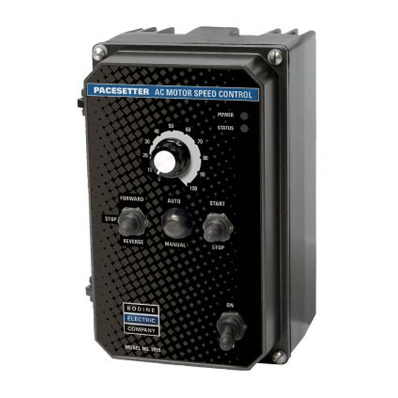
Page 9: Control Layout
COMP www.bodine-electric.com... -
Page 10: General Performance Specifications
(Volts AC) Phase) (Jumper J2) 2999 1 .75 0 - 208/230 1 3/4 1/2 1/4 1/8 5.9 208/230 Notes: 1. Bold indicates factory setting. Jumper J2 is labeled “1”, “3/4”, “1/2”, “1/4”, “1/8” (factory set to the “1” position). www.bodine-electric.com... -
Page 11: Mechanical Specifications
AC MOTOR SPEED CONTROL Hybrid Drive ™ 8.85 8.20 9.53 KBAC SERIES • NEMA 4X / IP 65 2.70 68.6 1.35 1.35 34.3 34.3 0.875 5.97 22.2 2.76 70.1 * Tighten these screws, in the sequence shown, to 12 lb-in. (14 kg-cm). www.bodine-electric.com... -
Page 12: Important Application Information
If the motor continues to be overloaded at the 120% level, the timer will shut down the drive after 30 minutes. If the motor is overloaded to 160% of full load, the drive will trip in 6 seconds. *UL approved as an overload protector for motors. www.bodine-electric.com... -
Page 13: Wiring Instructions
AC line input only (Terminals “L1”, “L2”). Rated for 208/230 Volt AC line input with Jumper J1 set to the “230V” position (factory setting). Rated for 115 Volt AC line input with Jumper J1 set to the “115V” position. See Figure 6. www.bodine-electric.com... -
Page 14: Remote Main Speed Potentiometer Connection
The switch assembly may be removed if a liquidtight seal is used to cover the hole in the front cover. After applying power to the drive, momentarily set the Start/Stop Switch to the “START” position. www.bodine-electric.com... -
Page 15: Start/Stop Function Eliminated
Violet (High) Enable Circuit Connection – Main Speed The drive can also be started Potentiometer and stopped with an Enable circuit (close to run, open to stop). See Figure 12. HIGH VOLTAGE! See Warning on Page 13. www.bodine-electric.com... -
Page 16: Drive Operating Condition And Run/Fault Relay Contact Status
Closed Open Mode* Operation Stop Selected by Open Closed Closed Open Mode* Operator Fault** Drive Tripped Open Closed Open Closed *Run Mode or Stop Mode is selected using the Start/Stop Switch. **Overload, I t, Short Circuit, Undervoltage and Overvoltage. www.bodine-electric.com... -
Page 17: Setting Selectable Jumpers
For 120 Hz output with 60 Hz motor, set Jumper J4 to the “2X” position and be sure Jumper J5 is set to the “60Hz” position. For 100 Hz output with 50 Hz motor, set Jumper J4 to the “2X” position and set Jumper J5 to the “50Hz” position. See Figure 20. www.bodine-electric.com... -
Page 18: Automatic Ride-Through Or Manual Restart Selection (Jumper J3)
Jumper J9 to the “NC” position. See Figure 24 on page Fixed or Adjustable Boost Selection 19. For wiring information, see Fixed Boost Section 5.5 on page 14. (Factory Setting) Adjustable Boost (J6 Installed in “FIX” Position) (J6 Installed in “ADJ” Position) www.bodine-electric.com... -
Page 19: Mounting Instructions
Operation with GFCI Circuit Breakers Inverter Duty Rated Motor Non Inverter Duty Rated Standard GFCI (Factory Setting) Motor Operation Sensitive GFCI (Factory Setting) (J11 Installed in “1” Position) (J11 Installed in “2” Position) J12 Installed in “GF2” Position) J12 Installed in “GF1” Position) www.bodine-electric.com... -
Page 20: Typical Hi-Pot Test Setup
www.bodine-electric.com... -
Page 21: Recommended High Voltage Dielectric Withstand Testing (Hi-Pot Testing)
Overvoltage Trip Point. 3. The Forward-Stop-Reverse Switch can be used to restart the drive. 4. If the Start/Stop Switch has been eliminated (bypassed), the AC line must be used to restart the drive after an Overload Fault has been cleared. www.bodine-electric.com... -
Page 22: Ac Line Fusing
2. When the Overload is removed, before the I t times out and trips the drive, the “ST” LED will flash green. 3. When the Undervoltage or Overvoltage condition is corrected, the “ST” LED will flash Red / Yellow / Green. www.bodine-electric.com... -
Page 23: Trimpot Adjustments
This will slow down the decrease speed to prevent the bus voltage from rising to the Overvoltage Trip point. This function is called Regeneration Protection. It is recommended that for very high inertial loads that both the ACCEL and DECEL Trimpots be set to greater than 10 seconds. www.bodine-electric.com... -
Page 24: Slip Compensation Trimpot (Comp) Range
Connect an AC RMS ammeter in series with one motor phase. Set the CL Trimpot fully counterclockwise. Adjust the speed setting to 30%. Lock the motor shaft and adjust the CL Trimpot to 160% of the motor nameplate rated current. www.bodine-electric.com... -
Page 25: Trip Time Vs. Motor Current
Increase the boost until the ammeter reaches the motor nameplate rated current (Amps AC). Using the Main Speed Potentiometer, slowly adjust the motor speed over a 1 – 15 Hz (0 – 450 RPM) range. If the motor current exceeds the nameplate rating, decrease the boost setting. www.bodine-electric.com... -
Page 26: Run-Stop-Jog Switch Connection
Contact our Customer Service Team. Figure 39 – Run-Stop-Jog Switch Connection (SPDT – Center Off) Jog Trimpot Main Speed Potentiometer Violet (High) (P3) Orange (Wiper) ACCEL DECEL BOOST COMP White (Low) (P1) (JOG) (P2) Run-Stop-Jog Switch (SPDT - Center O ) (Wiper) www.bodine-electric.com... -
Page 27: Limited Warranty
Bodine controls and Bodine controls used with non-Bodine motors and gearmotors are covered by a 12 month warranty period. The Bodine Electric Company will repair, replace, or refund at its option, any of its products which has been found to be defective and within the warranty period, provided that the product is shipped freight prepaid, with previous authorization, to Bodine or to a Bodine Authorized Service Center. - Page 28 Visit www.bodine-electric.com for all your motion control needs. Bodine offers the widest selection of variable-speed AC, permanent magnet DC and brushless DC fractional horsepower gearmotors and motors in the industry. For complete specifications, 3D CAD drawings, or to order online, visit bodine-electric.com.
Need help?
Do you have a question about the PACESETTER 2999 and is the answer not in the manual?
Questions and answers