
Subscribe to Our Youtube Channel
Related Manuals for Zennio KEM

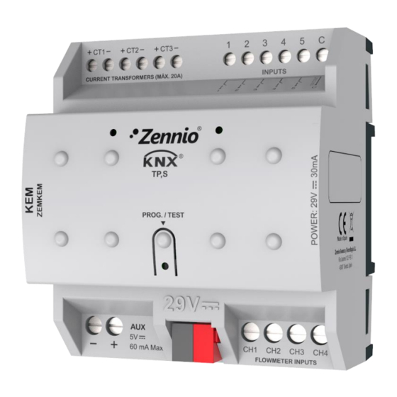
Summary of Contents for Zennio KEM
- Page 1 KNX Energy Monitor ZEMKEM Application program version: [1.0] User manual edition: [1.0]_a www.zennio.com...
-
Page 2: Table Of Contents
CONTENTS Contents ............................2 1 Introduction ..........................4 1.1 KEM ..........................4 1.2 Installation ........................5 1.3 Measured quantities ......................7 1.3.1 Electricity ........................7 1.3.2 Water ........................8 1.3.3 Heat/Cool quantity ....................8 1.4 Data inicialization after a download ................. 9 1.5 Setting the time of day .................... - Page 3 2.7.1 Binary input ......................38 2.7.2 Temperature probe ....................38 2.7.3 Motion detector ..................... 38 2.8 Logic functions ........................ 40 ANNEX I. Flow calculation ......................41 ANNEX II. Communication objects ....................42 http://www.zennio.com Technical Support: http://support.zennio.com...
-
Page 4: Introduction
Its use will ease a more efficient consumption of energy resources, resulting in savings for the user. KEM is able to measure and report in the KNX system the values of energy, water consumption and caloric energy along with other magnitudes related to these three. -
Page 5: Installation
KEM (7). The flow meter will be supplied from the 5V power output of KEM (5). Note that this output will only be live if at least one of the channels for water measurement is enabled in the parameterisation (see section 2.3). - Page 6 (return) of the air-conditioning circuit. For this purpose, the temperature probes incorporated in the flow meters and fittings supplied by Zennio can be used. Each one of these probes can be connected in any of the 5 analogue/digital inputs (1).
-
Page 7: Measured Quantities
1.3 MEASURED QUANTITIES Next, the quantities measured by the KEM that can be sent to the bus for monitoring are described. 1.3.1 ELECTRICITY Magnitudes of each conductor or phase: Current: rms value expressed in milliamps [mA]. Active power: effective power capable of transforming electrical energy into work. -
Page 8: Water
It is measured in joules [J]. Heat/cool quantity: sum of the calorific energy consumed during both heating and cooling. It is enabled by an ETS parameter and is always measured in joules [J]. http://www.zennio.com Technical Support: http://support.zennio.com... -
Page 9: Data Inicialization After A Download
It is important to note that global objects are always the sum of channels or phases, so it is not possible to set a value after download for these nor have flag W enabled. http://www.zennio.com Technical Support: http://support.zennio.com... -
Page 10: Setting The Time Of Day
For certain functionalities, such as periodic registers or the starting date of each register, it is necessary to set the time of day of KEM through a master clock in the installation. During the start-up, KEM will request the time of day to the KNX bus through the objects “Date”... -
Page 11: Configuration
/ disabled]: if this parameter is enabled, will be sent a periodic request for date and time every 15 minutes. The default values of each parameter will be highlighted in blue in this document, as follows: [default/rest of options]. http://www.zennio.com Technical Support: http://support.zennio.com... -
Page 12: Partial Registers: Global Configuration
In this tab you can configure the periodic reset of partial registers. In order for this tab to be displayed, it is necessary to have at least one partial record enabled for one of the magnitudes (electricity, water or heat quantity). See sections 2.2.1, 2.3.1 and 2.4.1. http://www.zennio.com Technical Support: http://support.zennio.com... - Page 13 In case of selecting “Same Day of Month”, the specific day of the month will change whenever the register is manually reset through the object “Reset Partial Registers n”. http://www.zennio.com Technical Support: http://support.zennio.com...
-
Page 14: Electricity
Within this tab, all the parameters related to electricity consumption monitoring are configured. 2.2.1 CONFIGURATION On this screen, the basic configuration common to all KEM phases can be selected. It is possible to enable or disable the different phases in addition to configuring some variables such as frequency and power factor. - Page 15 • Minimum Time Between Sendings [10…255][s]: sets a minimum period of time (seconds) between consecutive sendings. • Minimum Change to Send [[1…10…15300][W] / [1…15][kW]]: sets the minimum value change required to send the next value. http://www.zennio.com Technical Support: http://support.zennio.com...
- Page 16 Listed below are the objects that appear when the Show Global Objects option is enabled: ➢ “[Elec][Global] Disable”: when receives a ‘0’, measurements and sendings of all phases are stopped. ➢ “[Elec][Global] Consumed Active Energy”: stores the sum of the energy consumed by the different phases. http://www.zennio.com Technical Support: http://support.zennio.com...
- Page 17 On this screen can be configured the options related to phase objects, that is, those that refer to measures of a specific phase. ETS PARAMETERISATION The parameters shown in each phase tab are the following: Figure 9. Electricity - Phase x http://www.zennio.com Technical Support: http://support.zennio.com...
- Page 18 “[Elec][Phx][TR] Consumed Active Energy”. See section 2.2.2.1. 2.2.2.1 TOTAL REGISTER The total registers of magnitudes per phase store the accumulated values of energy consumption of one phase since the start-up of the device. ETS PARAMETERISATION The parameters to configure total registers are: http://www.zennio.com Technical Support: http://support.zennio.com...
- Page 19 Each time a partial register is restarted, the reset date is stored in “Starting Date Partial Registers n” and the values of the partial register are sent to the bus. Note: Partial registers are disabled by default. Please refer to section 2.2.1 for enabling them. http://www.zennio.com Technical Support: http://support.zennio.com...
- Page 20 2.2.2.1), applied to the configured partial register. Figure 11. Electricity - Phase x - Partial Register The energy values of the partial registers of each of the phases can be read through the objects “[Elec][Phx][PRn] Consumed Active Energy”. http://www.zennio.com Technical Support: http://support.zennio.com...
-
Page 21: Water
In addition to the electrical consumptions, KEM is able to monitor water flows and consumptions of up to 4 channels. 2.3.1 CONFIGURATION On this screen, the basic configuration common to all KEM channels can be selected. It is possible to enable or disable the different channels and water global objects. ETS PARAMETERISATION The “Configuration”... - Page 22 Figure 14. Water - Global - Sending Mode for Flow • Period [30…255][s] / [1…10…255][min / h]: sets the period between cyclical sendings. • Minimum Time Between Sendings [10…255][s]: sets a minimum period of time (seconds) between consecutive sendings. http://www.zennio.com Technical Support: http://support.zennio.com...
- Page 23 ➢ “Global Data Request”: this object appear when global object of electricity or water are enabled. For water magnitude, receiving a ‘1’ through this object, the global values of the consumed water flow are sent. http://www.zennio.com Technical Support: http://support.zennio.com...
- Page 24 Note: this parameter is only available if global water objects have been enabled in configuration tab (section 2.3.1). [Zennio 1/2” Flow Sensor / Zennio 3/4” Flow Sensor / Flow Sensor Type Custom Flow Sensor]: determines the type of sensor used for flow measurement.
- Page 25 Important: Although other models can be parameterised, the flow meter function is only guaranteed for the water flow sensors provided by Zennio. Sending Mode for Flow [Disabled / Periodic / With Value Change / Periodic and with Value Change]: analogous to the same parameter of the “Configuration”...
- Page 26 Each time a partial register is restarted, the reset date is stored in “Starting Date Partial Registers n” and the values of the partial register are sent to the bus. Note: Partial registers are disabled by default. Please refer to section 2.3.1 for enabling them. http://www.zennio.com Technical Support: http://support.zennio.com...
- Page 27 2.3.2.1), applied to the partial register being configured. Figure 18. Water - Channel x - Partial Register The volume values of the partial registers of each of the channels can be read through the objects “[Water][Chx][PRn] Consumed Water”. http://www.zennio.com Technical Support: http://support.zennio.com...
-
Page 28: Heat/Cool Quantity
2.4.1 CONFIGURATION On this screen, the basic configuration common to all KEM channels of heat quantity can be configured. It is possible to enable or disable the different channels and partial registers. -
Page 29: Heat Quantity X
One Object for Heat and Cool Quantity? / Yes]: allows to configure whether the objects of heat and cool quantity are independent or all the calorific energy is stored in the same object (“[Heat Qty][Chx][TR] Heat/Cool Quantity”). http://www.zennio.com Technical Support: http://support.zennio.com... - Page 30 Heat Quantity Value After Download [Keep Current Value / Value]: sets the initial value of the total register of heat quantity after an ETS download. When selecting “Set value”, an additional textbox appears to enter the desired value for heat quantity in Joules. http://www.zennio.com Technical Support: http://support.zennio.com...
- Page 31 Qty][Chx][TR] Cool Quantity” or “[Heat Qty][Chx][TR] Heat/Cool Quantity” will always be visible when the channel is enabled. These objects will store the calorific energy consumed by the system when heating and/or cooling. It can only be initialized by writing on it the desired value. http://www.zennio.com Technical Support: http://support.zennio.com...
- Page 32 Figure 23. Heat Quantity - Partial Registers The volume values of the partial registers of each of the channels can be read through the objects “[Heat Qty][Chx][PRn] Heat Quantity” and “[Heat Qty][Chx][PRn] Cool Quantity” or “[Heat Qty][Chx][PRn] Heat/Cool Quantity”. http://www.zennio.com Technical Support: http://support.zennio.com...
-
Page 33: Notifications
2.5 NOTIFICATIONS Notifications in KEM consist in sending a binary object to the KNX bus when the selected variables, stored in either total or partial registers, reach a pre-set value. The variables on which it is possible to configure notifications are water consumption and electricity consumption for global and individual magnitudes. - Page 34 Action [Send 0 / Send 1]: set the value to be sent through the binary object “Notification n: __________” when the notification is triggered. http://www.zennio.com Technical Support: http://support.zennio.com...
-
Page 35: Alarms
2.6 ALARMS In addition to notifications, KEM implements 7 alarms to monitor electric power, electric current and water flow, which can be enabled and parameterised independently. It will be possible to set an upper and a lower limit for any of the variables. When these limits are exceeded, the device will send a binary value through the different objects. - Page 36 This limit can also be set via the object “Alarm n: Set Upper Limit”. ➢ Action [Send 0 / 1]: set the value to be sent through the object “Alarm Send n: Excess _____” when the alarm is triggered. http://www.zennio.com Technical Support: http://support.zennio.com...
- Page 37 ➢ Hysteresis Above the Limit: defines a dead band for alarm deactivation. When active, the alarm will not be deactivated until a value over the limit plus hysteresis is reached. The units will coincide with those configured for the chosen channel/phase. http://www.zennio.com Technical Support: http://support.zennio.com...
-
Page 38: Inputs
Zennio website (www.zennio.com). 2.7.3 MOTION DETECTOR It is possible to connect motion detectors from Zennio to the input ports of KEM. This brings the device with the possibility of monitoring motion and presence in the room. - Page 39 Please refer to the specific user manual “Motion Detector”, (available in the KEM product section, at the Zennio website, www.zennio.com) for detailed information about the functionality and the configuration of the related parameters. http://www.zennio.com Technical Support: http://support.zennio.com...
-
Page 40: Logic Functions
KNX bus, and to send the results through other communication objects specifically enabled for this purpose. KEM can implement up to 10 different and independent functions, each of them entirely customisable and consisting in up to 4 consecutive operations each one. -
Page 41: Annex I. Flow Calculation
Hall effect sensor that emits an electrical pulse. The KEM measures the number of pulses read over a period of time (frequency), so it is necessary to apply the following formula to calculate the flow rate: ��... -
Page 42: Annex Ii. Communication Objects
C T R - - DPT_Value_Curr 0 - 20000 [Elec][Phx] Current Electrical Current (mA) Active Energy Consumption 18, 25, 32 4 Bytes I/O C T R W - DPT_ActiveEnergy 0 - 2147483647 [Elec][Phx][TR] Consumed Active Energy (Wh) http://www.zennio.com Technical Support: http://support.zennio.com... - Page 43 C - - W - DPT_Value_2_Ucount 0 - 65535 Alarm x: Set Upper Limit Set Upper Limit Value (L/h) 2 Bytes C - - W - DPT_Value_2_Ucount 0 - 15300 Alarm x: Set Upper Limit Set Upper Limit Value (W) http://www.zennio.com Technical Support: http://support.zennio.com...
- Page 44 1 Bit C T - - - DPT_UpDown [Ix] [Short Press] Move Up/Down Shutter Switching 0/1 (Up/Down) 1 Bit C T - - - DPT_Step [Ix] [Short Press] Stop/Step Up Shutter Sending of 0 (Stop/Step Up) http://www.zennio.com Technical Support: http://support.zennio.com...
- Page 45 [Ix] [Short Press] Shutter Status (Input) 0% = Top; 100% = Bottom 134, 140, 146, 152, 158 1 Byte C - - W - DPT_Scaling 0% - 100% [Ix] [Short Press] Dimming Status (Input) 0% - 100% http://www.zennio.com Technical Support: http://support.zennio.com...
- Page 46 C T - - - DPT_SceneControl 0-63; 128-191 [Ix] [Long Press] Save Scene Sending of 128 - 191 [Ix] [Switch/Sensor] Alarm: Breakdown or 1 Bit C T R - - DPT_Alarm 1 = Alarm; 0 = No Alarm Sabotage http://www.zennio.com Technical Support: http://support.zennio.com...
- Page 47 179, 184, 189, 208, 213, 1=Comfort Auto, Comfort, Standby, 218, 237, 242, 247, 266, 1 Byte C T R - - DPT_HVACMode 2=Standby [Ix] [Cx] Detection State (HVAC) Economy, Building Protection 271, 276, 295, 300, 305 3=Economy http://www.zennio.com Technical Support: http://support.zennio.com...
- Page 48 2 Bytes C T R - - DPT_Value_2_Count -32768 - 32767 [LF] Function x - Result (2-Byte) Signed 2 Bytes C T R - - DPT_Value_Temp -273.00º - 670760.00º [LF] Function x - Result (2-Byte) Float http://www.zennio.com Technical Support: http://support.zennio.com...
- Page 49 Join and send us your inquiries about Zennio devices: http://support.zennio.com Zennio Avance y Tecnología S.L. C/ Río Jarama, 132. Nave P-8.11 45007 Toledo (Spain). Tel. +34 925 232 002. www.zennio.com info@zennio.com...
Need help?
Do you have a question about the KEM and is the answer not in the manual?
Questions and answers