Table of Contents
Advertisement
Quick Links
Advertisement
Chapters
Table of Contents

Related Manuals for Baumer DAB10


Summary of Contents for Baumer DAB10
- Page 1 Operating Manual Measuring Amplifier EN-US DAB10...
-
Page 2: Table Of Contents
7.1.1 Process value Process Data In (PDI) ..................18 7.1.2 Status Bits Process Data In (PDI)....................19 7.1.3 Status Bits Process Data Out (PDO) ..................19 7.2 Observation ............................20 7.2.1 Peak value storage (memory values) ..................21 Operating Manual DAB10 | V1... - Page 3 7.3 Parameter ............................. 23 7.3.1 Parameterization of the sensor characteristics ................23 7.3.2 Low-pass filter..........................30 7.3.3 Parameterization of the analog output (DAB10-AI, DAB10-AU) ..........31 7.3.4 Parameterization SIO1/2......................35 7.3.5 Parameterization of the SSCx switching functions ..............37 7.4 Diagnosis .............................. 44 7.4.1 Remote operation ........................
-
Page 4: About This Document
In addition, the local occupational health and safety regulations and general safety regulations apply. The illustrations in this manual are examples only. Deviations are at the discretion of Baumer at all times. The product is not intended for permanent installation in automation systems. -
Page 5: Labels In This Manual
In addition, you can find the following information, among other things, in digital format at www.baumer.com: Operating manual Data sheet 3D CAD drawing Quickstart Dimensional drawing Connection diagram & pin assignment Certificates (EU conformity declaration, etc.) DAB10 | V1 Operating Manual... -
Page 6: Name Plate
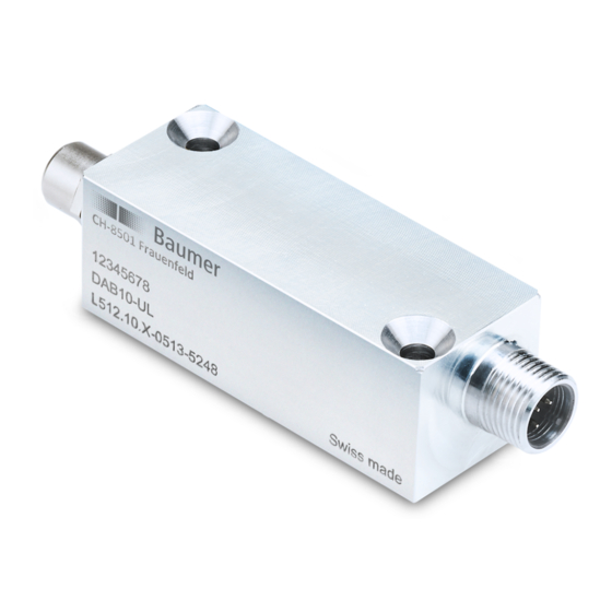
CH-8501 Frauenfeld, Switzerland Swiss made Ill. 1: Name plate Item number Denotation Serial number Return and repair In case of complaints, please contact the relevant sales unit. Accessories You can find accessories on the website at: https://www.baumer.com Operating Manual DAB10 | V1... -
Page 7: Safety
Do not dispose of electrical and electronic equipment in household waste. The product contains valuable raw materials for recycling, which is why the old prod- uct must be returned to an authorised collecting point for correct disposal/recy- cling. For further information see www.baumer.com. DAB10 | V1 Operating Manual... -
Page 8: Description
4 strain gauges and connected into a (Wheatstone) full bridge. The output depends on the product variation: Product variation Output DAB10-AI Analog output (current) IO-Link DAB10-AL IO-Link DAB10-AU Analog output (voltage) IO-Link Operating Manual DAB10 | V1... -
Page 9: Block Diagram And Signal Path
6. Output: The measuring amplifier presents either the process value, a peak value, or an S&H value via IO-Link or via an analog output (only for DAB10-AI and DAB10-AU). The switching thresholds are parameterized via SSC1/2 (Switching Signal Channel). The switching signals are presented via IO-Link (cyclic data) or via the 2 digital I/O pins. -
Page 10: Io-Link Communication (Overview)
Device status - Input delay for SIO1/2 Detailed Device status (up to 10 messages) Operating time (since response) Analog output (only for DAB10-AI & -AU): Operating time (service life) - Signal selection for analog output - Scaling of the analog output... -
Page 11: Dimensional Drawing
Baumer Description Dimensional drawing 2 x Ø 9,5 x 90° 2 x Ø 4,5 11,4 M12 x 1 M8 x 1 Ill. 3: Dimensional drawing DAB10 DAB10 | V1 Operating Manual... -
Page 12: Transport And Storage
Keep away from the sun. Avoid mechanical agitation. Storage temperature: -40 ... +85 °C Ambient humidity: 20 ... 85 % When storing for longer than 3 months, regularly check the general status of all parts and the packaging. Operating Manual DAB10 | V1... -
Page 13: Electrical Installation
Ground -V s IO-Link DAB10-AU DAB10-AU Control unit Transducer max. 10 m max. 10 m +V s L+ / +V s Supply voltage Voltage output L- / 0 Ground IO-Link / I/O -V s DI/DQ DAB10 | V1 Operating Manual... -
Page 14: Pin Assignment
0 V/L- DI/DQ Sensor side Sig + Sig - DAB10-AL Control side DI/DQ n. c. Sensor side Sig + Sig - DAB10-AU Control side +Vs/L+ Vout 0 V/L- DI/DQ Sensor side Sig + Sig - Operating Manual DAB10 | V1... -
Page 15: Commissioning
Baumer Commissioning Commissioning The measurement amplifier input is set as standard to 1 mV/V and thus directly matched to the Baumer force sensors. You can commission the measurement amplifier via plug & play. Factory settings DAB10-AI Value Input (sensor side): Process value unit:... -
Page 16: Parameterization Of The Measuring Amplifier
Parameterization of the measuring amplifier INFO To parameterize the measuring amplifier you need a USB IO-Link Master, the Baumer IO-Link Device Tool (parameterization software), as well as the IODD of the measuring amplifier. You can download the Baumer IO-Link Device Tool and the IODD at www.baumer.com. -
Page 17: Functions
Baumer Functions Functions With the help of the Baumer IO-Link Device Tools you have access to all functions of the mea- suring amplifier under the following 4 registers: Process data Observation Parameter Diagnosis Also see about this 2 Process data [} 18] 2 Observation [} 20]... -
Page 18: Process Data
(e.g. 100 N instead of 0.1 kN). Nominal value Resolution Display range as value in %FS in bit 0.01 0.0001 0.1 % 10.0 -0.0200 ... 0.0200 0.0001 0.01 % 13.3 -0.20000 ... 0.20000 0.0001 0.001 % 16.6 -2.00000 ... 2.00000 0.0001 0.0001 % 19.9 -20.00000 ... 20.00000 10000 0.0001 -20000.00000 ... 20000.00000 Operating Manual DAB10 | V1... -
Page 19: Status Bits Process Data In (Pdi)
Triggers a sensitivity teach-in (Teach-in sensitivity). sensitivity The function remains active as long as the bit is set. The function is only active if the parameter Teach-in.Sensitivity Enable is set to Enable. If not, this bit is not evaluated. DAB10 | V1 Operating Manual... -
Page 20: Observation
Presentation of the process value that was held during the last S&H trigger. Process Value.Sample and Hold Presentation of the difference between the process Delta value held during the last S&H trigger and the current process value. Operating Manual DAB10 | V1... -
Page 21: Peak Value Storage (Memory Values)
Ill. 4: Peak value storage The peak values are output via the cyclic process data and/or the analog output (the latter only for DAB10-AI and DAB10-AU). In addition, all storage values can be read out via IO-Link. DAB10 | V1 Operating Manual... -
Page 22: Sample And Hold
Ill. 5: Sample and Hold The values are output via the cyclic process data and/or the analog output (the latter only for DAB10-AI and DAB10-AU). In addition, all storage values can be read out via IO-Link. Operating Manual DAB10 | V1... -
Page 23: Parameter
▪ Offset teach-in (teach-in offset/taring) ▪ Sensitivity teach-in (teach-in sensitivity) Also see about this 2 Manual parameterization of the sensor characteristics (teach-in by value) [} 25] 2 Teaching in the sensor characteristics via the teach-in process [} 26] DAB10 | V1 Operating Manual... -
Page 24: Ill. 6 Convert The Input Signal Into The Process Value
Value (in positive and negative signal direction). Example: Nominal Process Value: 1000 N input signal range: -0.8 ... 1.2 mV/V (nominal) evaluable measurement range: ±(2 × 1000 N) = ±2000 N That corresponds: 0.2 ± (2 × 1 mV/V) = -1.8 ... 2.2 mV/V Meaning: process values lower than -2000 N or greater than +2000 N are not displayed (see Di- agnosis | Device Status). Operating Manual DAB10 | V1... - Page 25 Customer Sensor Adjustment.Nominal Sensitivity Enter the nominal sensitivity of the connected sensor (in mV/V). Customer Sensor Adjustment.Offset Enter the input signal at which a process value of 0 is presented (in mV/V). DAB10 | V1 Operating Manual...
- Page 26 The filter increases the precision for measuring the input signal. Also see about this 2 Offset teach-in (Teach-In Offset/Taring) [} 27] 2 Sensitivity teach-in (teach-in sensitivity) [} 28] 2 Filter Moving Average for offset and sensitivity teach-in [} 30] Operating Manual DAB10 | V1...
-
Page 27: Ill. 7 Offset Teach-In (With And Without Preload)
Subsequently, the value 0.2 is displayed under Parameter | Offset. 1'000 Offset teach-in with preload mV/V -2.0 -1.6 -1.2 -0.8 -0.4 Offset teach-in without preload -600 -800 -1'000 Ill. 7: Offset teach-in (with and without preload) DAB10 | V1 Operating Manual... - Page 28 Customer Sensor Adjustment.Process Value Unit = kN (the press force should be mea- sured) Customer Sensor Adjustment.Nominal Process Value = 100 (maximum force to be mea- sured) Teach-in.Offset Process Value = 0 Teach-in.Sensitivity Process Value = 50 kN Operating Manual DAB10 | V1...
-
Page 29: Ill. 8 Sensitivity Teach-In
-0.6 -0.4 -0.2 Reference point offset teach-in -100 Ill. 8: Sensitivity teach-in IO-Link parameter: sensitivity teach-in (teach-in sensitivity) Parameter designation Description Teach-in.Sensitivity Process Value Sensitivity teach-in Teach-in.Sensitivity Enable Enabling/disabling of sensitivity teach-in: 0: Disabled 1: Enabled DAB10 | V1 Operating Manual... -
Page 30: Low-Pass Filter
0: Disabled 1: Enabled Input Low Pass Filter.Frequency Select the limit frequency of the low-pass filter: 0: 1 kHz 1: 500 Hz 2: 200 Hz 3: 100 Hz 4: 50 Hz 5: 10 Hz 6: 10 Hz 7: 5 Hz 8: 2 Hz 9: 1 Hz Operating Manual DAB10 | V1... -
Page 31: Parameterization Of The Analog Output (Dab10-Ai, Dab10-Au)
Baumer Functions 7.3.3 Parameterization of the analog output (DAB10-AI, DAB10-AU) With the parameterization of the analog output you can carry out the following settings: Selection of the output signal (Signal Selection) Scaling the analog output (Signal Adjustment) Parameterization of the signal range of the analog output (Signal Alarm): 2-point adjustment... - Page 32 Process value of set point 1 Analog Output.Analog Signal 1 Analog output signal at set point 1 Analog Output.Process Value 2 Process value of set point 2 Analog Output.Analog Signal 2 Analog output signal at set point 2 Operating Manual DAB10 | V1...
- Page 33 In the register Diagnosis | Device Status the cause of the state of alarm is shown. IO-Link Parameter: parameterization of the alarm signal (Signal Alarm) Parameter designation Description Analog Output.Alarm Level of the analog signal when no valid measured value can be presented. DAB10 | V1 Operating Manual...
-
Page 34: Ill. 9 Parameterization Of The Analog Output (Example)
Analog Output.Analog Value = -2 V Maximum Process Value 1 & Process Value 1 & Analog Value 1 Analog Value 1 Minimum -1000 -800 -600 -400 -200 1000 Alarm Ill. 9: Parameterization of the analog output (example) Operating Manual DAB10 | V1... -
Page 35: Parameterization Sio1/2
Example: Settings.SIO1 Input Delay = 3 ms external signal Input delay internal Input delay Input delay signal Function activated Trigger function Ill. 10: Timing SIO1/2 DAB10 | V1 Operating Manual... - Page 36 12: Memory Reset (DO) 13: Sample & Hold (DO) 14: Teach-In Sensitivity (DO) Settings.SIOx Input Delay Set the input delay time (in ms). To ensure error-free set up of the IO-Link communication, we recommend at least 3 ms. Operating Manual DAB10 | V1...
-
Page 37: Parameterization Of The Sscx Switching Functions
(e.g. 10 N). Also see about this 2 SSC modes [} 38] 2 SSC Logic [} 39] 2 SSC Hysteresis [} 40] 2 Timing SSCx [} 42] DAB10 | V1 Operating Manual... -
Page 38: Ill. 11 Ssc Mode - Single Point
2 switching thresholds that indicate when then signal should switch to high and when it should switch to low. In this mode, the hysteresis is defined based on the setpoints. The hysteresis parameters have no effect in this mode. Operating Manual DAB10 | V1... -
Page 39: Ill. 14 Ssc Logic - Single Point, Inverted
SSC Logic SSC Logic Single Point, inverted Ill. 14: SSC Logic – Single Point, inverted SSC Logic Window, inverted Ill. 15: SSC Logic – Window, inverted SSC Logic Two Point, inverted Ill. 16: SSC Logic – Two Point, inverted DAB10 | V1 Operating Manual... - Page 40 Settings.SSCx Setpoint 2: 800 N Hysteresis.SSCx Alignment Mode: Left/Outer, Center, Right/Inner Hysteresis.SSCx Width: 100 N Single Point Window Left/ Outer Hyst Hyst Hyst 1000 1000 Center Hyst Hyst Hyst 1000 1000 Right/ Inner Hyst Hyst Hyst 1000 1000 Operating Manual DAB10 | V1...
- Page 41 Settings.SSCx Setpoint 2: 800 N Hysteresis.SSCx Alignment Mode: Left/Outer, Center, Right/Inner Hysteresis.SSCx Width: 100 N Single Point Window Left/ Outer Hyst Hyst Hyst 1000 1000 Center Hyst Hyst Hyst 1000 1000 Right/ Inner Hyst Hyst Hyst 1000 1000 DAB10 | V1 Operating Manual...
-
Page 42: Ill. 17 Response And Release Delay
Minimal Pulse Duration.SSCx Time: 4 ms Minimal Pulse Duration.SSCx Mode: 1 (positive and negative) SSCx Input signal Min. pulse Min. pulse Min. pulse Min. pulse duration duration duration duration SSCx Output signal Ill. 18: Minimal pulse duration Operating Manual DAB10 | V1... - Page 43 0: Disabled 1: Enabled Minimal Pulse Duration.SSCx Time Setting the minimal pulse duration (in ms). Minimal Pulse Duration.SSCx Mode Setting the pulse direction of the minimal pulse duration. 1: Positive and negative 2: Positive 3: Negative DAB10 | V1 Operating Manual...
-
Page 44: Diagnosis
0: Device is operating properly 1: Maintenance required 2: Out of specification 3: Functional check (Remote mode) 4: Failure (highest priority) Detailed Device Status For details see the attached table. Also see about this 2 Annex [} 46] Operating Manual DAB10 | V1... -
Page 45: Maintenance
Do not use scouring agents, solvents, or other aggressive cleaning agents. c) Do not use jets of liquid for cleaning, for example, a high-pressure cleaner. d) Do not scrape off soiling with sharp-edged items. Interior cleaning No interior cleaning of the device is required. DAB10 | V1 Operating Manual... -
Page 46: Annex
Annex Baumer Annex Also see about this 2 Error Handling [} 47] Operating Manual DAB10 | V1... -
Page 47: Error Handling
Error Handling Device Status Cyclic data Analog Description Condition Value Detailed Quality Bit Alarm Bit Process Value Output > 1 · Nominal Process Value 0xE4, 0x18, 0x00 Process value outside of nominal range Warning n.a. n.a. n.a. < -1 · Nominal Process Value 0xE4, 0x18, 0x01 21’001 >... - Page 48 List of illustrations Ill. 1 Name plate ............................Ill. 2 Measuring amplifier block diagram ..................... Ill. 3 Dimensional drawing DAB10 ......................11 Ill. 4 Peak value storage ..........................21 Ill. 5 Sample and Hold ..........................22 Ill. 6 Convert the input signal into the process value .................. 24 Ill.
- Page 50 Baumer Worldwide Belgium Brazil Canada Baumer SA/NV Baumer do Brasil Ltda Baumer Inc. BE-2260 Westerlo BR-13208-120 Jundiaí, São Paulo CA-Burlington, ON L7M 4B9 Phone +32 14 57 462 0 Phone +55 11 4523-5120 Phone +1 905 335 8444 China France Denmark Baumer (China) Co., Ltd.
Need help?
Do you have a question about the DAB10 and is the answer not in the manual?
Questions and answers