Advertisement
Quick Links
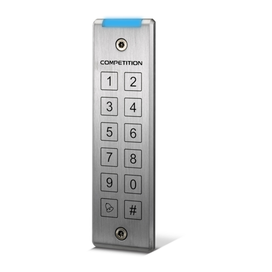
DG-180
System Keypad with Power Supply
•
Operating voltage 12Vdc
•
Aluminium alloy casing (vandal resistant screws for
enhanced safety and durability)
•
1000+10 PIN's
•
Touch panel keypad
•
Split off controller and keypad for high security
•
Non-volatile memory
•
Dual relay outputs (powered for multi-control)
•
Built in anti-tamper switch
•
Weather resistant: IP65
•
Vandal resitant
•
LED display and buzzer for status indication,
keypad with beep sound
WEATHER
VANDAL
RESISTANT
RESISTANT
− IP 65 −
6.7
44
1
2
3
4
5
6
150
7
8
9
0
#
Power Supply DG180
•
Power input 220Vac
•
Power output 12Vdc 2Amp
•
Battery charging circuit
•
Built-in timer circuit
Red
Black
Black + Brown = Reed
Door Closed = N.O.
Door Open = N.C.
White
Green
Brown
Ground 1
N.O.1
N.C.1
Varistor
P.B.1
Ground 2
+
Diode
N.O.2
N.C.2
Electric Lock 1
P.B.2
Fail-Safe
+
(MUST install
a Varistor)
Exit Button 2
Exit Button 1
Electric Lock 2
Fail-Secure
(MUST install a Diode)
Access control
+
+
DC OUT
Battery
+
12VDC IN
16VAC IN
C1
C2
GND
LOCK1
12VDC1
REX1
GND
LOCK2
12VDC2
REX2
For AC/DC
~
~
+
Setting the Standard in Access Control
Rechargeable
Battery
Power
Supply
+
For DC
use only
55
Advertisement

Related Manuals for ICS DG-180


Summary of Contents for ICS DG-180
- Page 1 Access control DG-180 System Keypad with Power Supply • Power Supply DG180 Operating voltage 12Vdc • • Aluminium alloy casing (vandal resistant screws for Power input 220Vac enhanced safety and durability) • Power output 12Vdc 2Amp • • 1000+10 PIN’s Battery charging circuit •...
- Page 2 Specification DG-180 Operating Voltage 12~24 VAC/VDC Digital Keypad Operation Manual Pull in: 50mA/12VDC Holding: 20mA/12VDC Current Draw ; Pull in: 80mA/24VDC Holding: 20mA/24VDC ; Keypad 6X2 matrix keypad (0~9, ,#) 2 contacts for Request-To-Exit Input 1 contact for Door Reed Switch Output 2 relays (N.O.
- Page 3 Note: Factory Default Setting: 1. It is suggested to use a linear power supply unit to prevent power rating reduction Master Code 1234(4-digit) from the keypad. Relay Strike Time 1 second 2. It is suggested to use #22~26 AWG insulation wire. Pressed Key Time Delay 5 seconds (Fixed) 3.
- Page 4 The GEM policy is one of continual development and improvement; therefore GEM 10. Changeing the length of the master code reserves the right to change specifications without notice. 1. Enter programming mode 2. Press (Yellow LED flash), press 04 Copyright © All Rights Reserved. P-MU-DG-180 Ver. D Publish: 2011.03.18...
Need help?
Do you have a question about the DG-180 and is the answer not in the manual?
Questions and answers