
Subscribe to Our Youtube Channel
Related Manuals for Et system EAC-4Q-KS Series


Summary of Contents for Et system EAC-4Q-KS Series
- Page 1 EAC-4Q-KS ET System electronic GmbH Telefon 06205 3948-0 Fax 06205 37560 Hauptstraße 119-121 info@et-system.de 68804 Altlußheim www.et-system.de...
- Page 2 INFO & CONTACT ADDRESSES ET System electronic GmbH was founded in 1986 in the heart of the Rhine-Neckar-Triangle. As a subsidiary of a leading electricity utility group, the company quickly took on a leading role in the area of laboratory power electronics and associated electrical measurement. The existing know-how in power technologies in the 90s gave rise to the “Power Solutions”...
- Page 3 Legal Notices Without the written permission and consent of ET System, no part of this manual may be used, copied, translated, modified, or transmitted in any form. All the information, instructions and illustrations provided in this manual are the latest version currently. This manual is based on the technical status at the time of printing.
-
Page 4: Safety Requirements
To prevent potential hazards, please follow the instructions in the manual to safely use the instrument. ET System have no liability for failures caused by violate protective measures or other safety regulations. -
Page 5: Safety Notices And Symbols
SHOCK HAZARD The risk of electrical hazards. For example: The maximum voltage of EAC-4Q-KS series can reach 750VDC and above, which may cause personal injury or death. To avoid the risk of electrical hazards, the equipment must be firmly connected to the ground wire and other equipment wiring;... -
Page 6: Table Of Contents
Summary of safety requirements ....................4 Safety Notices and Symbols ......................5 Chapter 1 Equipment Introduction ..............9 System Overview ......................10 1.1.1 Overview of EAC-4Q-KS series ................ 10 1.1.2 Model description ....................10 1.1.3 Features and configuration ................10 1.1.4... - Page 7 Power-on Operation ....................33 GUI Software Operation (Local Control) ............... 34 GUI Software Operation (Remote Control) ............36 Power off Operation ....................36 Chapter 4 Function and Feature Introduction ............ 38 Grid Simulation Function ................... 39 Constant Current Output Function ................. 42 AC+DC/AC/DC Output ....................
- Page 8 6.1 1 Verity equipment and settings ................ 70 6.1.2 Verity content ......................72 Test Record Form ......................77 Chapter 7 Equipment Maintenance and Repair ......... 78 Equipment Maintenance .................... 79 7.1.1 Equipment operating environment..............79 7.1.2 Equipment maintenance ..................79 Equipment Repair ......................
-
Page 9: Chapter 1 Equipment Introduction
Chapter 1 Equipment Introduction 1.1 System Overview 1.1.1 Overview of EAC-4Q-KS series 1.1.2 Model description 1.1.3 Features and configuration 1.1.4 General specification 1.2 Appearance and Structure of Equipment 1.2.1 Appearance and outline 1.2.2 Front panel 1.2.3 Rear panel 1.2.4 Internal structure 1.2.5... -
Page 10: System Overview
1.1 System Overview 1.1.1 Overview of EAC-4Q-KS series The ET System EAC-4Q-KS series is a high-performance AC/DC power source, using SiC MOSFET PWM technology, which contains multi output power levels from 15kVA to 500kVA. With an output frequency range from DC to 2kHz (standard 1kHz, 2kHz with -HF option), standard output 300V L-N (higher voltage can be customized). -
Page 11: General Specification
• CE Conformity • Mod-bus/SCPI protocols 1.1.4 General Specification AC Input 3P+N+PE,380VLL±10%(Std) Voltage Frequency 47-63Hz Efficiency ≥85% Power Factor 0.95 Output Output Modes AC, DC, or AC+DC From 15kVA to 90kVA in single cabinet. Power Level Max paralleled system power 500kVA. Voltage Ranges 0-300V (Std), voltage can be customized. - Page 12 Voltage Slew Rate 5V/us DC output Voltage Range 0-550V (Std), voltage can be customized. Voltage Accuracy 0.2%FS Voltage Ripple 0.1%FS Current Range Max 25A per 15kVA module Current Accuracy 0.1%FS Max Power, Voltage and Current are the same as AC+DC Mode DC Mode AC Voltage Measurement Accuracy 0.5%FS...
-
Page 13: Appearance And Structure Of Equipment
1.2 Appearance and structure of Equipment 1.2.1 Appearance and outline The overall appearance of the EAC-4Q-KS (take EAC-4Q-KS 45-300-50 as an example) is shown in Figure 1-1. There are lifting rings at the top of the cabinet for lifting operation, and moving rollers at the bottom of the cabinet, which for users to move flexibly. -
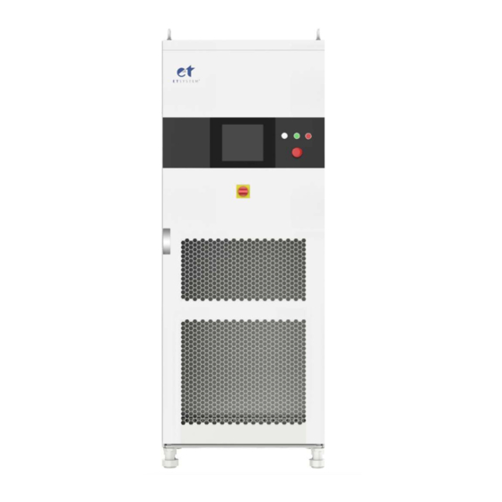
Page 14: Front Panel
1.2.2 Front Panel The front panel of EAC-4Q-KS series is equipped with a TFT-Touch panel displayer (12 inch), status indicator, power knob, emergency stop button and RS232 interface (optional). Figure 1-2 Front panel Table 1-1 Number Name Notes ① White Light The power supply is standby. -
Page 15: Rear Panel
1.2.3 Rear panel The rear panel of EAC-4Q-KS series is equipped with RS485 / LAN interface (standard), TTL interface and ATI interface (optional). Figure 1-3 Rear panel Table 1-2 Number Name Note RS485 interface Standard configuration, is used for remote control. -
Page 16: Internal Structure
④component layer, wiring layer and other interface layers. Figure 1-4 Internal structure 1.2.5 Front panel of control module The front panel of EAC-4Q-KS series control module is equipped with LAN interface (standard), fan and power switch. Figure 1-5 Front panel of control module... - Page 17 Table 1-3 Number Number Notes ① LAN interface Standard, for touch screen communication ② LAN interface Standard, for debugging and firmware update ③ For control module heat dissipation Power switch ④ For the power on / off the control module...
-
Page 18: The Component Layer, Connection Layer And Other Interface Layers
1.2.6 The component layer, connection layer and other interface layers The power input/output wiring copper bar, 220V auxiliary terminal, external emergency stop interface and others are showed when remove the bottom baffle, as shown in Figure 1-6. Figure 1-6 Power input / output connection layers Table1-4 Number Name Notes... -
Page 19: Interface Description
1.3 Interface Description 1.3.1 LAN interface (standard) The LAN interface is one of the equipment communication interfaces. 1.3.1.1 Location of LAN interface The two LAN interfaces on front panel of the control module are used for touch panel communication (Figure 1-7①) and hardware debugging (Figure 1-7②). Figure 1-7 front panel of the control module IMPORTANT INFORMATION The LAN interface (Figure 1-7①) is connected to the touch panel by default before... -
Page 20: Rs485 Interface (Standard)
Figure 1-9 Rear panel 1.3.2.2 Connection of RS485 interface The RS485 interface of EAC-4Q-KS series adopts "two-wire + signal ground" wiring. In low-speed, short-distance, non-interference occasions, ordinary twisted-pair wire can be used. Conversely, in high-speed and long-line transmission, RS485 special cable (STP-120Ω 18 AWG) (one pair) with... -
Page 21: Rs232 Interface (-232 Option)
impedance matching (generally 120Ω) must be used. In the environment with severe interference, armored twisted pair shielded cable (ASTP-120Ω 18AWG) (one pair) should also be used. The connection method is shown in Figure 1-10. Figure 1-10 Connect RS485 The port setting information: Port: COM port on control PC Baud Rate:... - Page 22 Figure 1-13 Front panel of the power supply 1.3.3.2 Connection of RS232 interface The RS232 interface usually appears in the form of 9 pins (DB-9). Under normal circumstances, two RS232 interfaces, one male and one female, can be used by directly plugging in the interconnect.
-
Page 23: Ttl Interface (Standard)
DSR(Data Set Ready) Data Set Ready ← RTS(Request To Send) Request To Send → CTS(Clear To Send) Clear To Send ← RI(Ring Indicator) Ring Indicator ← The port setting information: Port: COM port on control PC Baud Rate: 9600 Data Bits: Stop Bits: Parity: None... -
Page 24: Ati Interface (-Ati Option)
Connection of TTL interface 1.3.4.2 Figure 1-14 Connect TTL interface 1.3.5 ATI Interface (-ATI option) T he output voltage of power supply can be controlled via control signals and by using the analog input (ATI interface). EAC-4Q-KS uses BNC connector for this analog input. Set points are adjusted as dc voltage (0-5 V) on the analog input. - Page 25 Figure 1-15 Rear panel of power supply 1.3.5.2 Connection of ATI interface The ATI interface of the EAC-4Q-KS series appears as BNC. The connection between the equipment and the signal generator is shown in Figure 1-16. Figure 1-16 Connect ATI interface...
-
Page 26: External Emergency Stop Interface (Standard)
1.3.6 External emergency stop interface (standard) The EAC-4Q-KS series provides an external emergency stop interface, which can be connected to the user's external emergency stop switch. When an emergency occurs, the user does not need press the emergency button on power supply. To achieve protection action quickly, only need to press this switch. -
Page 27: Chapter 2 Equipment Installation
Chapter 2 Equipment Installation 2.1 Check before Installation 2.1.1 check the packing 2.1.2 check the equipment 2.2 Equipment Installation 2.2.1 Selection of input/output cables 2.2.2 Installation steps 2.2.3 Add single-phase output (-1P option) -
Page 28: Check Before Installation
Check before Installation 2.1.1 Check the packing when receiving the power supply of EAC-4Q-KS series, if the packing is damaged, do not dispose the damaged packing or cushioning materials before checking the integrity of the goods and electrical / mechanical testing. The shipper/carrier should be responsible for product damage caused by the shipment. -
Page 29: Equipment Installation
2.2 Equipment Installation 2.2.1 Selection of input/output cables Before installing the equipment, the user should confirm the model on the nameplate, select cables of appropriate specifications according to the equipment input/output voltage and current rating of the equipment. If the input/output current is greater than 125A, it is necessary to select the appropriate specifications of the cold end (as shown in Figure 2-1), crimp the input side cable and the output side cable. - Page 30 Step 2: The copper bars (PE / N / A / B / C) on the input side and the copper bars (DC + / DC-) for the DC connection on the output side are shown in Figure 2-4. The cables are connected to wiring terminal through the inlet hole at the bottom.
-
Page 31: Add Single-Phase Output (-1P Option)
Figure 2-5 Equipment wiring completion status 2.2.3 Add single-phase output (-1P option) The EAC-4Q-KS series with the -1P option adds a single-phase output function. By changing the wiring method (parallel three-phase output terminals, as shown in Figure 2-6), the output current can be increased to three times the single-phase current. -
Page 32: Chapter 3 Power-On Operation
Chapter 3 Power-on Operation 3.1 Power-on Operation 3.2 GUI Software Operation (Local Control) 3.3 GUI Software Operation (Remote Control) 3.4 Power-off Operation... -
Page 33: Power-On Operation
SHOCK HAZARD The maximum voltage generated by EAC-4Q-KS series product can reach to 750V, which could result in personal injury or death. When power is on, do not touch exposed connectors or components. Make sure that there is no overvoltage on the product (such as overvoltage caused by lightning), otherwise there may be a risk of electrical hazards. -
Page 34: Gui Software Operation (Local Control)
Figure 3-3 Front Panel 3.2 GUI Software Operation (Local Control) EAC-4Q-KS series provide GUI software, it is installed in the touch panel, which uses windows OS. (the software can also be installed on the control PC connected to the power supply). - Page 35 Figure 3-4 Front Panel Figure 3-5 Indicators of Touch screen software All functions and parameters can be set and run through the touch screen displayer. The software has the following functions: - Output settings and limits - Sequence output settings Including working mode, output power, output voltage, output current, duration, switching time settings, storage, and re-import of complex sequences;...
-
Page 36: Gui Software Operation
3.3 GUI Software Operation (Remote Control) The detail information is in 5.2. 3.4 Power off Operation Step 1: Close the GUI software on the TFT-Touch panel displayer/PC and shut down. Step 2: Turn the power knob counterclockwise (Figure 3-9⑤). Figure 3-9 Front panel Step 3: Open the cabinet door and power off the control unit switch (Figure 3-10④). - Page 37 IMPORTANT INFORMATION Closing the switch on the front panel of the control box at the first time. Tthis step can be ignored when the power is off, it will always remain closed. when the power supply is turned on, the step of closing the switch can be omitted, which is convenient for users to operate.
-
Page 38: Chapter 4 Function And Feature Introduction
Chapter 4 Function and Feature Introduction 4.1 Grid Simulation Function 4.2 Constant Current Output Function 4.3 AC+DC/AC/DC Output... -
Page 39: Grid Simulation Function
4.1 Grid Simulation Function KS series uses bi-directional design, and can be used as grid simulator to test distributed generation systems, such as the electrical characteristics of energy storage PCS, PV inverter, etc. The simulation functions include voltage and frequency fluctuation, voltage drop, low/zero voltage, three-phase unbalance, harmonic and inter-harmonic etc. - Page 40 on the measurement panel, such as input current/voltage, output current/voltage/power, etc. Figure 4-3 Measurements panel KS series can also capture, display, and save the output voltage and current Waveforms and store them inside the power supply for retrieval and analysis by users. Figure 4-4 Waveform browsing panel The KS series can edit up to the 40th harmonic and inter-harmonic, and users can capture Waveforms through the oscilloscope.
- Page 41 Figure 4-5 Harmonic/Inter-harmonic edit Figure 4-6 Harmonic waveform Figure 4-7 Inter-harmonic waveform KS series can be used for low/zero voltage ride through test. KS series provide standard software for the low voltage ride through test of photovoltaic inverters, which can be used to simulate grid voltage/frequency changes, drops and sags to meet the low voltage ride through test requirements of photovoltaic inverters.
-
Page 42: Constant Current Output Function
4.2 Constant Current Output Function The EAC-4Q-KS Series uses true current feedback control when working in CC mode. It is different from power supplies using voltage feedback with constant current mode, which is called voltage controlled current. -
Page 43: Ac+Dc/Ac/Dc Output
4.3 AC+DC/AC/DC Output The EAC-4Q-KS series adopts Bi-directional design and can be used as an AC/DC power supply to test DUT. Output modes include AC, DC, AC+DC. The details software setting will be introduced in 5.7. -
Page 44: Chapter 5 Software Interface
Chapter 5 Software Interface 5.1 GUI Software Introduction 5.1.1 Operating status 5.1.2 Sequence mode 5.1.3 Input/output controls 5.2 Communication Setting 5.3 Hardware Limits 5.4 CV/CC Mode 5.5 Sequence Mode 5.6 Analog Input 5.7 AC+DC/AC/DC 5.7.1 AC+DC 5.7.2 5.7.3 5.8 Harmonic and inter-harmonic simulation 5.8.1 Harmonic simulation 5.8.2... -
Page 45: Gui Software Introduction
5.1 GUI Software Introduction 5.1.1 Operating status EAC-4Q-KS series provides GUI software, which is installed on the front touch screen using the windows OS. (the software can also be installed on the control PC connected to the power supply). A few seconds after the power supply is initialized, the control unit and touch screen work, the power supply is standby. -
Page 46: Sequence Mode
The red light indicates the equipment automatically stops working ② Fault when a fault occurs during operation. If the equipment runs in normal, the light is dark green. When equipment is operating normally and output AC/DC, the green ③ Output light is always on. -
Page 47: Input/Output Controls
Input Mode Analog input via ATI interface (-ATI option). AC+DC AC+DC output mode. ③ Output Mode DC output mode. 5.1.3 Input/output controls There are some important controls on the sequence panel (Figure 5-2③).Click "Apply" → "Start" → "Power On" → "Start" → "Output On", the power supply is on, click "Output On" →... -
Page 48: Communication Setting
5.2 Communication Setting Before establishing a network connection between the power supply and the remote workstation/PC, make sure that the remote workstation/PC and the power supply are on the same network segment. The default network address of the power supply is 192.168.1.2, the port is 502, and the default gateway is 255.255. - Page 49 In general, the hardware of workstation/PC connecting to the power supply must follow the requirements: Processor: Intel core 2 duo or above RAM:2GB or above Operating System:Windows 7 or above 10/100/1000 Mbps network port adaptor Network Switch (LAN users) ...
-
Page 50: Hardware Limits
5.3 Hardware Limits To operate safety, please set the relevant protection parameters before the formal test. Operation steps: Click "Hardware Limits" to enter the panel (Figure 5-7). After setting the parameters, click "Apply". Figure 5-7 Hardware limits panel Table 5-4 Number Name Note... -
Page 51: Cv/Cc Mode
The EAC-4Q-KS series provides GUI software. Users can select different operating modes on the right side of the sequence mode panel according to test requirements. In both modes, a variety of parameter settings are supported, including output phase voltage/phase current, phase angle, frequency, on/off phase angle, dwell time, and switching time. -
Page 52: Sequence
5.5 Sequence The output parameters of the EAC-4Q-KS series power supply can be controlled through GUI software. The sequence mode interface supports a variety of parameter settings, including output phase voltage/phase current, phase angle, frequency, on/off phase angle, dwell time, and switching time. - Page 53 Table 5-5 Number Name Note Real-time The current output voltage, current and power of the power supply ① parameters displays in Real time. The user can set the output phase voltage/phase current, phase Parameter ② angle, frequency, dwell time and switching time of each step. The setting 1 right side of each step is the serial number and valid check box.
-
Page 54: Analog Input
5.6 Analog Input The output voltage of EAC-4Q-KS series can be controlled by control signal and using analog input (ATI interface). The ATI interface is located on the rear panel of power supply, please refer to 1.3.5 for specific connection. The BNC connectors for analog input is used in KS series. The set value will be adjusted according to the AC/DC voltage (0-5 V) of the analog input. -
Page 55: Ac+Dc/Ac/Dc
5.7 AC+DC/AC/DC 5.7.1 AC+DC The EAC-4Q-KS series support AC+DC output mode. Test steps: Click "Sequence" to enter the panel, select AC+DC output mode (AC+DC) on the right side (Figure 5-13①), the user can choose different operating modes (CV/CC) according to the test requirements, and set the AC voltage/current (Figure 5-13②) and DC offset voltage/current... - Page 56 5.7.2 AC The KS series allows the generation of AC voltage, current and waveform, which can simulate the real AC circuit conditions. Three-phase independent programmable control and have high accuracy. Test steps: Click "Sequence Mode" to enter the sequence mode test panel, select AC+DC output mode (AC+DC) on the right side of the panel (Figure 5-13①), the user can select different operating modes (CV/CC) according to the test requirements, and set the AC voltage/current (Figure 5-13②).
- Page 57 Figure 5-14 DC output mode...
-
Page 58: Harmonic And Inter-Harmonic Simulation
5.8 Harmonic and inter-harmonic simulation 5.8.1 Harmonic simulation EAC-4Q-KS series provide complete GUI software, which can edit up to the 40th harmonic and inter-harmonics. Test steps: Click "Sequence Mode" to enter the panel, firstly set the basic operating parameters (such as output voltage, frequency). -
Page 59: Inter-Harmonic Simulation
① Harmonic selection box After checking, the harmonic setting is valid. After checking, the three-phase harmonics can be set at ② Coupling box the same time. If unchecked, three-phase harmonics can be set independently. Three-phase harmonic setting button, the panel is shown in Figure 5-16 will automatically pop up after clicking it. - Page 60 parameter setting is completed, check the corresponding box, and click "Setting" → "Apply" in turn. To cancel the inter-harmonic simulation, click the inter-harmonic setting button at the bottom of the page (Figure 5-17), click "Clear" in the pop-up panel to clear all parameters, click "Setting" → "Apply"...
-
Page 61: Measurements
5.9 Measurements The GUI software of KS series can monitor the input/output status of the equipment in real time. Click "Measurement" to enter the panel (Figure 5-17). The user can monitor real-time Input current/voltage/power, output current/voltage/power, output frequency and other parameters on this panel. -
Page 62: Waveform
5.10 Waveform 5.10.1 Real-time waveform browsing The GUI software of EAC-4Q-KS can record the waveform of output voltage and current, and store in the TFT touch panel/workstation, for the user to retrieve browsing and analysis in future Steps: Click "waveform" to enter the panel (Figure 5-20). In the window of waveform browsing, the user can individually or simultaneously select the data of output voltage or output current (Figure 5-20⑦) and browse the waveform. -
Page 63: Historical Waveform Browsing
Retrieve the historical Waveform data, click it to pop up the ③ Historical Data historical waveform browsing window as shown in Figure 5-19. Click pause control, the waveform will stop updating and stay on ④ Pause the captured. Check “Save”, the data in the waveform browsing window will be ⑤... -
Page 64: System Status
By checking different boxes on the left side of the panel, the corresponding output voltage/current and DC bus voltage waveform s can be observed. Click the partial zoom button and drag the mouse, the Waveform area in the box will be partially enlarged (Figure 5-22-1); click the horizontal/vertical zoom button and drag the mouse, the waveform between the cursors can be zoomed horizontally/vertically (Figure 5-22-2 and Figure 5-22-3);... - Page 65 Figure 5-23 System status panel-main system status Figure 5-24 System status panel- software fault...
-
Page 66: Administrator Account
Figure 5-25 System status panel- module fault 5.12 Administrator Account Enter the administrator account, the user can set the internal parameters. For avoiding accidental settings leading to equipment failure or loss of accuracy, it is not recommended that the user perform this operation. The default login account is a guest account, and all functions of the equipment are open and can be used normally. -
Page 67: Waveform Reproduction Function
5.13 Waveform Reproduction Function The EAC-4Q-KS series can realize the waveform reproduction function by importing the waveform data file (.csv) agreed with the user. Operation Steps: (1) Click "Playback" to enter the waveform reproduction panel, click "Power On" (Figure 5-27④) to start the network side. - Page 68 select "Enable" and then click "Import" to import the curve (.csv file) (Figure 5-28). Ratio Enlargement or reduction ratio of waveform data.. Sampling [ms] Sampling time of waveform data. ② Start Time [ms] Start time of waveform data. End Time [ms] End time of waveform data.
-
Page 69: Chapter 6 Equipment Verification And Calibration
Chapter 6 Equipment verification and calibration 6.1 Performance Verification 6.1.1 Verify equipment and settings 6.1.2 Verify content Voltage Range Current Range Frequency Range Voltage Accuracy Current Accuracy Power Accuracy Frequency Accuracy Output Characteristics Load Regulation Voltage THD Ripple Test Harmonic Test Inter-harmonic Test Voltage drop Change Three phase Unbalanced Output... -
Page 70: Performance Verification
Performance Verification 6.1 1 Verity equipment and settings Figure 6-1 Three-phase output test with resistive load Figure 6-2 Single-phase output test with resistive load Figure 6-3 Load step change test... - Page 71 SHOCK HAZARD Danger of electrical hazards, lethal voltage, the maximum voltage generated by EAC-4Q-KS series can reach 750VDC and above! Make sure that all equipment and load wiring are connected reliably. When connecting / disconnecting any equipment which connected to the power...
-
Page 72: Verity Content
6.1.2 Verity content • Voltage Range Connect the input side of the AC/DC source to the power grid, so that the input voltage is within the operating voltage range of the power supply, and the output side is connected to a pure resistive load. - Page 73 pure resistive load. Set the output voltage value to make the power supply work within the rated output current range, read and record the output current measurement value on the power analyzer and the power supply, and take the largest error for calculation. The current accuracy is obtained by the following formula: And: ——Current Accuracy;...
- Page 74 And: ——Power Accuracy; �� �� ——Power value measured via power analyzer, kW; �� —— Power value displayed on power supply, kW; �� ——Rated Power, kW; �� �� • Output Characteristics Connect the input side of the AC/DC source to the power grid, so that the input voltage is within the operating voltage range of the power supply, and the output side is connected to a pure resistive load.
- Page 75 resistive load, so that the output voltage and output current reach the maximum value specified by the product, read and record the AC voltage indication value, and take the maximum value in the test. The ripple coefficient is obtained by the following formula: And: ——Ripple coefficient;...
- Page 76 • Step Load Change Connect the input side of the AC/DC source to the power grid, so that the input voltage is within the operating voltage range of the power supply, and the output side is connected to a pure resistive load through an AC contactor. When the AC power is output to 200V, control the AC contactor to on/off, and record the oscilloscope waveform.
-
Page 77: Test Record Form
3. Adjust the load or output voltage so that the output current is greater than 1.2 times the rated value. The power supply will immediately start the protection function and cut off the output. 4. Adjust the temperature setting value of the software program. When the current measured temperature is greater than 10% of the software setting temperature, the power supply will immediately cut off the output and give an alarm. -
Page 78: Chapter 7 Equipment Maintenance And Repair
Chapter 7 Equipment Maintenance and Repair 7.1 Equipment Maintenance 7.1.1 Equipment operating environment 7.1.2 Equipment maintenance 7.2 Equipment Repair 7.2.1 Equipment self-test 7.2.2 Maintenance service 7.2.3 Equipment returns... -
Page 79: Equipment Maintenance
Equipment Maintenance Please be careful of the maintenance environment of equipment. ET System has no liability for failures caused by breaking equipment rules. 7.1.1 Equipment operating environment • The equipment is used indoors, and the operating temperature is not higher than 40 ° C and not lower than 0 °... -
Page 80: Equipment Repair
CAUTIOUS Do not disassemble the equipment. If there is any problem, please contact the agent or ET System. ET System has no liability for equipment failure caused by self-assembly. 7.2.2 Maintenance service If the purchased equipment failure during the warranty period, ET System will repair the equipment according to the specific information provided by the customer. -
Page 81: Chapter 8 Programming
Chapter 8 Programming 8.1 Command Format 8.1.1 Parameters data type 8.1.2 Command parameters/Return value units 8.1.3 Command format 8.2 Command Sets 8.2.1 Common commands 8.2.2 SCPI and panel comparison 8.3 Example... -
Page 82: Command Format
Reactive Power KVA (Kilovolt-ampere) Time mS (Millisecond) 8.1.3 Command format The command set of the EAC-4Q-KS series are divided into the following two command formats: <*>command characters<?> e.g., *IDN? or Remote? Command characters_<value> e.g., POWER 1 or SET: VOLT 100.0... -
Page 83: Command Sets
8.2 Command Sets 8.2.1 Common commands Commands Return Value Description Return: Return the information of *IDN EAC-4Q-KS-AC***-*** equipment Firmware Versioin 1.0 *RST None Fault Rest Inquire status Remote/Local. It will return 1 Remote? Remote,1/0 if working in Remote mode, else return 0. Check if there is a fault. - Page 84 Set the value of limitation for LIMIT:CUR <NRf> None current CF=1.414 Inquire the value of limitation LIMIT:CUR? LIMIT: CUR<,NRf> for current CF=1.414 Set the mode of output to CV MODE CV/CC None or CC Return mode of output MODE? MODE 1/0 1:CC 0:CV Set Input mode of reference...
- Page 85 Inquire value SET:AMPB? SET: AMPB<,NRf> amplitude of B Inquire the value of phase of SET:PHASEC? SET: PHASEC<,NRf> Inquire value SET:AMPC? SET: AMPC<,NRf> amplitude of C Set the values of following parameters for one time: Frequency; phase of A; <NRf1><,NRf2><,NRf3><,NRf4 None amplitude of A;...
- Page 86 Measure voltage VOLT:B? VOLT:B<NRf> output B Measure voltage VOLT:C? VOLT:C<NRf> output C VOLT<NRf1><,NRf2><,NRf3 Measure voltage VOLT? ><,NRf4><,NRf5><,NRf6> output A~C Measure current CUR:A? CUR:A<,NRf> output A Measure current CUR:B? CUR:B<,NRf> output B Measure current CUR:C? CUR:C<,NRf> output C CUR<,NRf1><,NRf2><,NRf3 Measure current CUR? >...
-
Page 87: Scpi And Panel Comparison
Inquire the frequency of FREQ:B? FREQ:B<NRf> output B Inquire the frequency of FREQ:C? FREQ:C<NRf> output C FREQ<NRf1><,NRf2><,NRf3 Inquire the frequency of FREQ? > output A~C MEAS<,NRf1><,NRf2><,NRf Inquire measured MEAS? 3><,NRf4><,NRf5><,NRf6> parameters of power supply. …… FCODE<,NRf1><,NRf2><,NR Inquire fault code FCODE? f3><,NRf4><,NRf5><,NRf6>... - Page 88 Inquire the value of Over Current OCP? OCP <,NRf> Protection Inquire the value of Over Power OPP? OPP <,NRf> Protection value limitation LIMIT:CUR <NRf> None current ;CF=1.414 Inquire the value of limitation for LIMIT:CUR? LIMIT:CUR <,NRf> current; CF=1.414 2.(Sequence) Figure 8-2 Commands Return Value Description...
- Page 89 Clear the sequence’s parameters in SEQ CLEAR None sequence mode and the current step return to 1 Go to next step of sequence in SEQ INC None sequence mode Set output frequency inactivated step SEQ:FREQ <NRf> None in sequence mode Set the phase of output A in activated SEQ:PHASEA <NRf>...
- Page 90 SEQ:LAB<NRf> Set the sequence step number Inquire the sequence number of SEQ:LAB? SEQ:LAB<,NRf> current step Inquire output frequency have been set SEQ:FREQ? SEQ:FREQ<,NRf> inactivated step in sequence mode Inquire the phase of output A have SEQ:PHASEA? SEQ: PHASEA<,NRf> been set inactivated step in sequence mode Inquire the amplitude of output A in SEQ:AMPA?
- Page 91 Inquire values following parameters for one time: LAB; duration; switch time; SEQ<NRf1><,NRf2><,NRf3> output frequency; <,NRf4><,NRf5><,NRf6><,N the phase of output A; SEQ? Rf7><,NRf8><,NRf9><,NRf1 the amplitude of output A; 0><,NRf11><,NONE/A/B/C the phase of output B; ><,ON/OFF> the amplitude of output B; the phase of output C; the amplitude of output C;...
- Page 92 Validate the parameters that have been SEQ APPLY None set in sequence mode. 3.(Harmonic) Figure 8-3 Commands Return Value Description Set second harmonic parameters: Harmonic order; HARM phase of a; <NRf1><,NRf2><,NRf ratio of a; 3><, NRf4><, None phase of b; NRf5><,NRf6><, ratio of b;...
- Page 93 HARM CLEAR None Clear harmonic setting parameters 4. Inter Harmonic Setting Figure 8-4 Commands Return Value Description Set inter harmonic parameters of Channel IHARM Channel; <NRf1><,NRf2><, Frequency; NRf3><, phase of a; None NRf4><,NRf5><, ratio of a; NRf6><, NRf7> , phase of b; ratio of b;...
-
Page 94: Example
Channel; Frequency; phase of a; ratio of a; phase of b; ratio of b; phase of c; ratio of c; Validate the parameters that have been IHARM APPLY None Clearing inter harmonic parameter IHARM CLEAR None setting 8.3 Example 1) Query information *IDN EAC-4Q-KS-AC***-*** Firmware Versioin 1.0 Remote? - Page 95 5) Inquire Measure VOLT:A?;VOLT:B?;VOLT:C? VOLT:A220.00;VOLT:B220.00;VOLT:C220.00; 6) Power up in normal mode MODE CV SET:FREQ 50 SET:PHASEA 0 SET:AMPA 220 SET:PHASEB-120 SET:AMPB 220 SET:PHASEC -240 SET:AMPC 220 SET? SET50.00,0.00,220.00,-120.00,220.00,-240,220 SET APPLY POWER ON POWER:STAT? POWER:STAT1 OUTPUT ON OUTPUT:STAT? OUTPUT:STAT1 VOLT:A? VOLT:A 220.00 CUR:A? CUR:A10.00 POW:A?
- Page 96 SEQ:PHASEC -240 SEQ:AMPC 220 SEQ:SWT 100 SEQ:DUT 100 SEQ:CONDSEL NONE SEQ:CONDVAL 0 SEQ:OUTPUT ON SEQ? SEQ1.00,100.00,100.00,50.00,0.00,220.00,-120.00,220.00,-240.00,220.00,0.00,0.00,1.0 SEQ:INC SEQ:LAB? SEQ:LAB2 SEQ:FREQ 50 SEQ:PHASEA 0 SEQ:AMPA100 SEQ:PHASEB -120 SEQ:AMPB 100 SEQ:PHASEC -240 SEQ:AMPC 100 SEQ:SWT 100 SEQ:DUT 100 SEQ:CONDSEL NONE SEQ:CONDVAL 0 SEQ:OUTPUT ON SEQ? SEQ2.00,100.00,100.00,50.00,0.00,100.00,-120.00,100.00,-240.00,100.00,0.00,0.00,1.0...
- Page 97 CUR*.*,*.*,*.* POW? POW*.*,*.*,*.*...
Need help?
Do you have a question about the EAC-4Q-KS Series and is the answer not in the manual?
Questions and answers