
Related Manuals for Meilhaus Electronic ME-6000 Series


Summary of Contents for Meilhaus Electronic ME-6000 Series
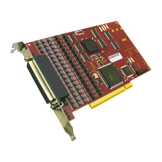
- Page 1 Meilhaus Electronic Manual ME-6000 Series 3.0E (ME-6000/6100/6200/6300) 16-bit D/A Conversion Board with up to 16 Channels and Electrical Isolation (optional: “Island Channels”)
- Page 2 Electronic assumes no responsibility for its use, any infringements of patents or other rights of third parties which may result from use of this manual or the product. Meilhaus Electronic assumes no responsibility for any problems or damage which may result from errors or omissions.
-
Page 3: Table Of Contents
Content Introduction ............5 Important Notes ............... 5 1.1.1 Use in Accordance with the Requirements ....... 5 1.1.2 Improper Application ............6 1.1.3 Unforeseeable Misapplications ........6 Package Contents ............. 7 Features ................7 System Requirements ............9 Software Support ............. 9 Starting up ............ - Page 4 B1 D-Sub Connector (ST1) ............26 B1.1 ME-6000/6100 ............26 B1.2 ME-6200/6300 ............27 B2 Auxiliary Connector (ST2) ............28 Accessories ................29 Technical Questions ..............31 D1 Hotline .................. 31 Index ..................32...
-
Page 5: Introduction
Important Notes 1.1.1 Use in Accordance with the Requirements The PC boards of the ME-6000 series are designed for acquisition and output of analog and digital signals with a PC. Depending on type, install the models of the ME-6000 series into:... -
Page 6: Improper Application
As a basic principle, all connections to the board should only be made or removed in a powered-down state of all components. Ensure that no static discharge occurs while handling the board or while connecting/disconnecting the external cable. Ensure that the connection cable is properly connected. -
Page 7: Package Contents
We take great care to ensure your delivery is complete. Nonethe- less, please check the list enclosed to verify the contents of your delivery. You should find included: D/A conversion board of the ME-6000 series for PCI- resp. Com- pactPCI-bus. ... - Page 8 = “p“ one another („Island Channels“) Depending on the model the boards of the ME-6000 series pro- vides 4, 8 or 16 D/A channels for bipolar voltage output in the out- put range ±10 V as well as 16 digital I/Os. Each channel has its own high-accuracy, high-speed 16-bit D/A converter.
-
Page 9: System Requirements
OEM-versions please contact our sales department under the phone number: +49 8141 52 71-0. System Requirements The ME-6000 series may be installed into any PC with a free standard PCI-, PCI-Express- resp. CompactPCI-slot (32 bit, 33 MHz, 5 V). The board is supported by the Meilhaus Electronic Intelligent Driver System (ME-iDS). -
Page 10: Starting Up
First choose a di- rectory on your computer (e.g. C:\Temp\Meilhaus\ME-iDS). Use the Meilhaus Electronic Intelligent Driver System (ME-iDS) for programming your new data acquisition hardware. For installation and operation of the driver system, please follow the documenta- tion in electronic form included with the software package. -
Page 11: Hardware
Hardware Block Diagrams ME-6000/4: 4 D/A channels ±10 V (U _0…3), 16 DIOs ME-6000/8: 8 D/A channels ±10 V (U _0…7), 16 DIOs 16 D/A channels ±10 V (U _0…15), 16 DIOs ME-6000/16: ME-6100/4: 4 D/A channels ±10 V (U _0…3), with FIFO, 16 DIOs ME-6100/8:... -
Page 12: D/A Section
*Depending on the version not all functional groups available. D/A Section Depending on model, the boards of the ME-6000 series provides up to 16 analog output channels. Each channel has its own serial 16- bit D/A converter and converts up to 500 kS/s. -
Page 13: Notes For Wiring
The output voltage range of the “U-Plus”-channels (ME-6200/ME- 6300) is from 0 V to+50 V-1LSB if the standard output buffer is used. 3.2.1 Notes for Wiring Attention: After power up, the standard D/A channels output - 10 V. After starting the driver the output value changes to 0 V. To guarantee... -
Page 14: Electrical Isolation
a defined power-up condition please start your host computer first and do not power up your external wiring until the driver started. The “U-Plus”-channel of the ME-6200/6300 outputs 0 V immedi- ately after power up. Important Note! Make sure that a reference from the external wiring to PC ground is made. -
Page 15: Island Channels
3.2.3 Island Channels With the “p”-Option (“Island Channels”) all the D/A channels use in- dependent ground levels and supply pins. I.E. you have to connect the ground reference of each channel (GND_0…15) with the appro- priate GND of your external application. Further on, every island channel requires an independent, symmetrical power supply of ±15 V (±22 mA per channel for I = ±15 mA). -
Page 16: Option "High Current
3.2.4 Option “High Current” The option “High Current” (HC) can be combined with the board versions without “island channels”. It gives you the possibility to in- crease the output current per channel to I = ±15 mA. This re- quires an external, low-noise power supply of ±15 V (±22 mA per channel for I = ±15 mA) and a change to your hardware –... -
Page 17: Digital-I/O Section
It is important that the voltage levels of the external trigger input wiring be within the specified limits (see specifications on page 22) and that a reference to ground (GND_ ) be made. The opto-isolated trigger inputs work with a high level of +5 V. For low level a current I of 7.5 mA ≤... - Page 18 It is important that the voltage levels of the digital input/output wiring be within the TTL level limits (see specifications on page 22) and that a reference to PC ground (PC_GND) be made. The maxi- mum output current is I = 10 mA.
-
Page 19: Programming
Programming For programming the device please use the Meilhaus Electronic In- telligent Driver System (ME-iDS) included in your package. The ME- iDS is a unique driver system covering different devices and operat- ing systems. It supports Windows 2000 and higher and contains a... -
Page 20: Timer Controlled Output
CompactPCI boards provide two 8-bit-wide digital-I/O ports (A, B). Each port is considered as a unique subdevice I the Meilhaus Electronic Intelligent Driver System (ME-iDS) and can be independently configured as input or output. On power up, all ports... -
Page 21: Simple Input/Output
are set to input. The assignment of the ports to the subdevices can be found in the ME-iDS help file (see ME-iDS Control Center). For wiring the digital ports please read chapter 3.3 on page 17. The following operation modes are possible: 4.2.1 Simple Input/Output ME-6000/6200 ME-6100/6300... -
Page 22: Appendix
Appendix Specification (Ambient temperature 25 º) PC-Interface Standard-PCI- resp. CompactPCI-bus (32 bit, 33 MHz, 5 V PCI Local bus specification version 2.1 compliant; CompactPCI Specification PICMG 2.0 R3.0, Resources assigned automatically (Plug&Play) Voltage Outputs (Partly different specifications are valid for the „U-Plus“-channel – see separate section) Number of channels 4, 8 or 16 (depends on model) - Page 23 Total accuracy „With electrical isolation“ max. ±20 mV „With island channels“ max. ±10 mV Operation modes „Single“, „Streaming“ Trigger modes software start, ext. digital trigger, synchronous start (software/external) External trigger edges rising, falling, any Timer-Controlled Output (ME-6100/6300, channel 0…3) Channels 0…3 (independent of one other) D/A-FIFOs 8 k values per channel...
- Page 24 Digital I/Os Ports 2 x 8 bit Reference to ground PC ground (PC_GND) Port type bidirectional TTL ports Output level max. 0.5 V bei 24 mA min. 2.4 V bei -24 mA Input level max. 0.8 V bei Vcc = 5 V min.
-
Page 25: B Pinout
Pinout Legend for pinouts: Attention: With the options “High Current” and “Island Channels” the pins –U_x and +U_x are inputs for the external ±15 V power supply. In all other cases these pins output ±15 V and it is not permitted to connect them. -
Page 26: B1 D-Sub Connector (St1)
D-Sub Connector (ST1) B1.1 ME-6000/6100 *Note the warning on page 25. -
Page 27: B1.2 Me-6200/6300
B1.2 ME-6200/6300 *Note the warning on page 25. -
Page 28: B2 Auxiliary Connector (St2)
Auxiliary Connector (ST2) Adapter cable (ME-AK-D25F/S (cPCI)) from 20-pin IDC connector to mounting bracket with 25-pin D-Sub female connector (comes with the board). Attention: When connecting the mounting bracket make sure to plug in pin 1 of the flat ribbon cable (red marked line) as shown above to the IDC connector ST2. -
Page 29: C Accessories
Accessories We recommend to use high-quality connector cables with single- shielded lines per channel. As accessory we provide the special connector cable ME-AK-D78/6000M-OE (length: 1 m). ME-AK-D78/6000M-OE Special connector cable from 78-pin D-Sub male connector to 16 single-shielded lines with open end. Note the warning on page 25. - Page 30 ME-63Xtend Series External relay and digital-I/O boards (DIN rain mounting possible). Connection by ST2 with additional mounting bracket ME AK-D25F/S and special connection cable ME AK-D2578/4000. ME-UB Series Desktop relay and digital-I/O boxes. Connection by ST2 with addi- tional mounting bracket ME AK-D25F/S and special connection ca- ble ME AK-D2515/4000.
-
Page 31: D Technical Questions
Download-Server and Driver Update: To download current driver versions for Meilhaus Electronic devices as well as manuals in PDF format, please go to: www.meilhaus.org/driver Service Department with RMA Process: In case you need to return a board for repair purposes, we strongly ask you attach a detailed description of the error as well as infor- mation regarding your computer/system and the software used. -
Page 32: E Index
Index Improper Application ............6 Introduction ..............5 Island Channels ............. 15 Accessories ..............29 Appendix ............... 22 Option “High Current” ..........16 Block Diagrams .............. 11 Package Contents ............7 Pinout ................25 Programming ..............19 D/A Section.............. 12, 19 Digital-I/O Section ...........
Need help?
Do you have a question about the ME-6000 Series and is the answer not in the manual?
Questions and answers