
Related Manuals for Meilhaus Electronic ME-582 Series


Summary of Contents for Meilhaus Electronic ME-582 Series
- Page 1 Meilhaus Electronic Manual ME-582x Series Opto-Isolated Digital-I/O Board with Bit-Pattern Detection, 3 x 16-bit Counters (8254 compatible) (alternatively: Frequency Measurement and Pulse Generator)
- Page 2 Important note: The information contained in this manual has been reviewed with great care and is believed to be complete and accurate. Meilhaus Electronic as- sumes no responsibility for its use, any infringements of patents or other rights of third parties which may result from use of this manual or the prod- uct.
-
Page 3: Table Of Contents
3.7 External Interrupt ..................19 Programming ..............20 4.1 Single Operation Mode ................22 4.1.1 Digital Input/Output ............... 22 4.1.2 Frequency Input/Output ..............23 4.1.2.1 Frequency Measurement ..........24 4.1.2.2 Pulse Generator ..............25 4.1.3 Counters (8254)................25 Content page 3 Meilhaus Electronic... - Page 4 4.2.1 Bit-Pattern Change ............... 27 4.2.2 Bit-Pattern Compare ..............28 Appendix ................29 Specification .................... 29 Pinout ...................... 36 78-pin D-Sub (ST1) — ME-582x .............. 37 Accessories ..................... 38 Technical Questions ................39 Hotline ..................... 39 Index ......................40 Content page 4 Meilhaus Electronic...
-
Page 5: Introduction
Revision 0.9 Introduction Valued customer, Thank you for purchasing this device from Meilhaus Electronic. You have chosen an innovative high-technology product that left our premises in a fully functional and new condition. Please take the time to carefully examine the contents of the package for any loss or damage that may have occurred during shipping. -
Page 6: Improper Application
“ME-5820” or “ME-5821” is used to describe special features of these versions. If required, certain subdevices can alternatively be configured for fre- quency measurement or for pulse generation (see chapter 4 from page 20). 1 Introduction page 6 Meilhaus Electronic... - Page 7 The isolation voltage between the opto-isolated inputs/outputs and PC-ground is 1 kVAC The opto-isolated digital inputs of the ME-582x are equipped with an overvoltage protection diode that can discharge voltage pulses to ground for a short period of time. 1 Introduction page 7 Meilhaus Electronic...
-
Page 8: System Requirements
Meilhaus Electronic Intelligent Driver System (ME-iDS). Software Support The ME-series is supported by the Meilhaus Electronic Intelligent Driver System (ME-iDS). The ME-iDS is a unique driver system covering different devices and operating systems. It supports Windows 7, 8.1, 10 and con- tains a universal function library (API) for all common programming lan- guages. -
Page 9: Initial Operation
First choose a directory on your computer (e.g. C:\Temp\Meilhaus\ME-iDS). Use the Meilhaus Electronic Intelligent Driver System (ME-iDS) for pro- gramming your new data acquisition hardware. For installation and opera- tion of the driver system, please follow the documentation in electronic form included with the software package. -
Page 10: Hardware
Pinout picture of the 78-pin D-sub female connector in the appendix (see “Pinout” page 36). In the following chapters you will learn more about the external wiring of the functional sections. Chapter 4 from page 20 describes the operation modes and the programming. 3 Hardware page 10 Meilhaus Electronic... -
Page 11: Me-582X Pxie
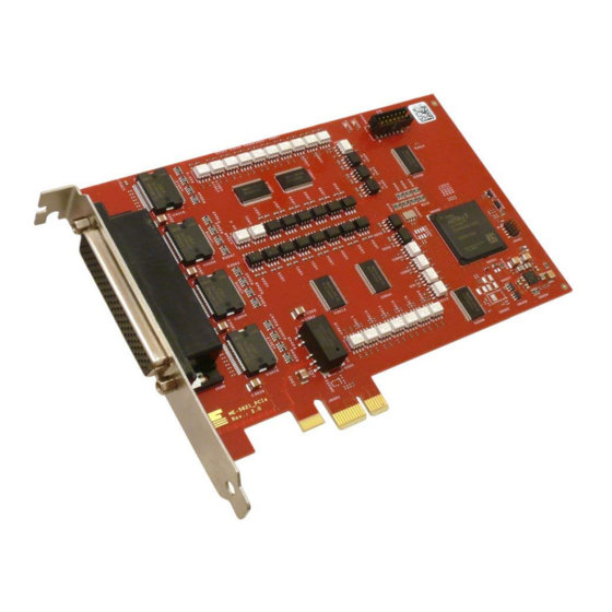
Manual ME-582x Series Revision 0.9 ME-582x PXIe Picture 2: ME-5821 PXIe ME-582x PCIe Picture 3: ME-5821 PCIe 3 Hardware page 11 Meilhaus Electronic... -
Page 12: Digital Input/Output
GND_EXT (pins 9, 11, 59) has to be setup in any case. The input lines show logic “0” if not con- nected. Picture 4: Inputs of the ME-5820 3 Hardware page 12 Meilhaus Electronic... -
Page 13: Opto-Isolated Outputs
= 1 W per chip (DO_x 0…7 = chip 1, DO_x 8…15 = chip 2), see picture 6 and 7. + … + P ≤ 1 W (per chip by 70 ºC) ⋅ U with P 3 Hardware page 13 Meilhaus Electronic... - Page 14 To supply the sink output drivers, an external power supply has to be con- nected to VCC_EXT (Pin 10, 20) with sufficient power (depending on the application). At full load this means min. 0.8 A for the ME-5820 and min. 1.6 A for the ME-5821. 3 Hardware page 14 Meilhaus Electronic...
-
Page 15: Source Driver
0.180 A Table 2: Max current of the source driver To supply the source output drivers, an external power source has to be connected to VCC_EXT (pin 10, 20), with sufficient power (depending on 3 Hardware page 15 Meilhaus Electronic... -
Page 16: Frequency Input/Output
This versatile chip has 3 independent 16-bit (downward) counters. All counter signals are available at the D-sub female connector. With a suitable enabling of the GATE input (0 V) the related counter will start downward-counting with negative edge control. The counter clock 3 Hardware page 16 Meilhaus Electronic... -
Page 17: Wiring Of The Counters
(GND_EXT). Logic “0” means that the output is in a high-im- pedance state. The polarity of the input signals (CLK_x and GATE_x) is inverted by the opto-couplers. All counter signals require a reference to external ground GND_EXT (pins 9, 11, 59). 3 Hardware page 17 Meilhaus Electronic... -
Page 18: Pulse Width Modulation
The following picture shows the external wiring of the counters for the ME- 5820 series. For programming the PWM output please read the ME-iDS user manual and the ME-iDS help file (see ME-iDS Control Center). Picture 10: PWM wiring ME-5820 series 3 Hardware page 18 Meilhaus Electronic... -
Page 19: External Interrupt
As soon as the specified event occurs, an interrupt is issued and passed directly to the PC. The digital inputs/outputs are programmed in the single operating mode. The interrupt handling is carried out with the meIOIrq… functions; see also chapter 4.3 on page 26. 3 Hardware page 19 Meilhaus Electronic... -
Page 20: Programming
Manual ME-582x Series Revision 0.9 Programming For programming the device please use the Meilhaus Electronic Intelligent Driver System (ME-iDS) included in your package. The ME-iDS is a unique driver system covering different devices and operating systems. It supports Windows 7, 8.1 and 10 and contains a universal function library (API) for all common programming languages (the extent of the current software support can be found in the README-files of the ME-iDS). - Page 21 Depending on your application you can choose one of the following oper- ating modes: Single: In this mode single values can be read or written. Interrupt: For interrupt processing in the modes bit-pattern change and bit-pattern compare (see chapter 4.3.1 from page 27). 4 Programming page 21 Meilhaus Electronic...
-
Page 22: Single Operation Mode
The subdevices are defined as follows: subdevice 0 of the ME-5820 and additional subdevice 5 for ME-5821 always are the type ME_TYPE_DI and subdevice 1 and respectively subdevice 6 (ME5821) of type ME_TYPE_DO. The subtype of the subdevice is ME_SUBTYPE_ SIN- GLE. 4 Programming page 22 Meilhaus Electronic... -
Page 23: Frequency Input/Output
The programming of the frequency measurement and the pulse generator is always done in the single operation mode. The subtype of the subde- vices is always ME_SUBTYPE_SINGLE. Picture 122: Frequency input/output in single operation mode 4 Programming page 23 Meilhaus Electronic... -
Page 24: Frequency Measurement
300 kHz. The resolution is 1 tick = 15.15 ns. The meas- urement always starts at a rising edge. On the ME-5820, all 4 frequency measuring channels (FI_A0…3) are addressed as subdevices of type 4 Programming page 24 Meilhaus Electronic... -
Page 25: Pulse Generator
82C54 provides three 16-bit counters. Each counter is accessed as a subdevice of type ME_TYPE_CTR, subtype ME_SUB- TYPE_CTR_8254. Note the order of operation as described in the ME-iDS manual and in the ME-iDS help file (see ME-iDS Control Center). 4 Programming page 25 Meilhaus Electronic... -
Page 26: Standard Operation Modes
Programming the digital input/output is carried out in the operation mode single. The subdevice must have the type ME_TYPE_DI. The interrupt processing is controlled with the functions meIOIrq… 4 Programming page 26 Meilhaus Electronic... -
Page 27: Bit-Pattern Change
7 for a rising edge. A rising edge now is to arrive at bit 7, so that an interrupt is issued and in the interrupt status value bit b 23 returns 4 Programming page 27 Meilhaus Electronic... -
Page 28: Bit-Pattern Compare
If the state changes from une- qual to equal or from equal to unequal, an interrupt is generated (see pic- ture 17 on page 28). Picture 17: Bit-pattern compare 4 Programming page 28 Meilhaus Electronic... -
Page 29: Appendix
Frequency output sig- symmetrical rectangular max. 3 kHz signal option „wraparound“ max. 3 kHz, without load for the Host PCs Timer (CHAN-time) input 30.30 ns…65 s (2..FFFFFFFFHex Ticks) 0.15 ms…65 s output (11000..FFFFFFFF- Hex Ticks) 5 Appendix page 29 Meilhaus Electronic... - Page 30 External supply Lmax For further specifications see chapter sink driver resp. source driver Sink Driver (UDN2803) Measured Test Criterion Type MAX Unit Quantity (output cur- per channel rent) See also characteristics curves in picture 18 5 Appendix page 30 Meilhaus Electronic...
- Page 31 (short-circuit proof with current limiting and temperature monitoring) Voltage supply =15…30 V, TJ=-25…+125 °C Conditions: U Measured Test Criterion Type MAX Unit Quantity =24 V; 1 channel with 23.8 =0,625 A /channel 1 channel 5 Appendix page 31 Meilhaus Electronic...
- Page 32 Limiting Values Measured Test Criterion Type MAX Unit Quantity (housing °C switch-off temperature) (housing reset °C temperature) (junction °C switch-off temperature) (junction reset °C temperature) (DC-short- = 24 V, R =10 mΩ circuit current) 5 Appendix page 32 Meilhaus Electronic...
- Page 33 16.25 s (0.06 Hz) max.asym 32.5 s (0.03 Hz) max.sym Duty-cycle variable, depending on T to be set in steps of 1 tick Resolution 1 tick 15.15 ns Accuracy ± 15.15 ns 5 Appendix page 33 Meilhaus Electronic...
- Page 34 Quantity/Criterion Interrupt sources passed directly to bit-pattern change the PC bit-pattern compare General Data Measured Condition/Explanation Value Quantity/Criterion Power supply PXI-Express +3,3 V (via PXIe-Bus) PCI-Express +3.3 V (via PCIe-Bus) 0.8…1.2 A (full-load) PXI-Epress 5 Appendix page 34 Meilhaus Electronic...
- Page 35 3 U PXI-Express board (without slot bracket PCI-Express 162 mm x 98 mm connector) Connections 78-pin D-sub female socket Operating 0 °C…70 °C temperature Storage -40 °C…100 °C temperature Air humidity 20 %…55 % (non-condensing) Certification 5 Appendix page 35 Meilhaus Electronic...
-
Page 36: B Pinout
DO_B4..15 (ME-582x) and DO_D4..15 (ME-5821). When used as sink drivers they are in high-impedance state, when used as source drivers they are connected to ground! *These signals are only available on ME5821 5 Appendix page 36 Meilhaus Electronic... -
Page 37: B1 78-Pin D-Sub (St1) - Me-582X
*These pins can only be used as frequency measurement inputs (FI_x) resp. pulse generator outputs (FO_x) after appropriate configuration of the corresponding subdevice with the ME-iDC. The remaining pins of the digi- tal ports cannot be used for digital-I/O. 5 Appendix page 37 Meilhaus Electronic... -
Page 38: C Accessories
Manual ME-582x Series Revision 0.9 Accessories We recommend to use high-quality connector cables with single-shielded lines per channel. For further accessories please refer to the current Meilhaus Electronic cat- alog and the internet: www.meilhaus.de/en/pc-boards/accessories/ 5 Appendix page 38 Meilhaus Electronic... -
Page 39: D Technical Questions
Download-Server and Driver Update: To download current driver versions for Meilhaus Electronic devices as well as manuals in PDF format, please go to: www.meilhaus.org/driver Service Department with RMA Process: In case you need to return a board for repair purposes, we strongly ask you attach a detailed description of the error as well as information regard- ing your computer/system and the software used. -
Page 40: Index
Model overview Counters Opto-Isolated Inputs Digital Input/Output 12, 22 Package Contents Pinout Programming External Interrupt Single Sink driver Software Installation Features Software Support Frequency measurement Specifications System Requirements Hardware Technical Questions Test Program Important Notes 5 Appendix page 40 Meilhaus Electronic...
Need help?
Do you have a question about the ME-582 Series and is the answer not in the manual?
Questions and answers