Table of Contents
Advertisement
Quick Links
Advertisement
Table of Contents

Subscribe to Our Youtube Channel
Related Manuals for Burkert 7604


Summary of Contents for Burkert 7604
- Page 1 Type 7604 Micro diaphragm pump 11 mm Operating Instructions...
-
Page 2: Table Of Contents
Intended use ................3 ▶ Keep the manual and make it available to every user. Basic safety instructions .............. 3 ▶ There is no liability or guarantee for Type 7604 if the instructions are not followed. Product description ..............5 Symbols Technical data ................ -
Page 3: Intended Use
BASIC SAFETY INSTRUCTIONS These safety instructions do not take into account any unforeseen Micro diaphragm pump Type 7604 solely serves as a micro dia- circumstances and events which occur during installation, oper- phragm pump for the media permitted as per the data sheet. - Page 4 Risk of short-circuit NOTE! Escape of medium due to leaking fittings. Electrostatically sensitive components / assemblies! ▶ Make sure seals are properly seated. The device contains electronic components that are susceptible ▶ Carefully screw together the micro diaphragm pump and manifold. to the effects of electrostatic discharging (ESD).
-
Page 5: Product Description
Malfunction ▶ Do not use Type 7604 outdoors without the appropriate hous- Integrated impulse generator The micro diaphragm pump can optionally be equipped with an ing and avoid heat sources that may cause the permissible integrated impulse generator. -
Page 6: Installation
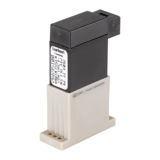
Voltage tolerance ±10% 00156992 Identification number of the device Power consumption 1.5 W Type label (example) INSTALLATION 7604 FFKM PK CAUTION! 1,5W >4,5 ml/min Risk of injury due to high pressure and escaping medium. @35 Hz W18MA ▶ Before working on the device or system, switch off the pressure. - Page 7 Fluidic connection WARNING! Risk of injury due to improper installation ▶ Only trained technicians may perform installation work. ▶ Only carry out installations with suitable tools. ▶ Secure the system against unintentional activation. Following installation, ensure a controlled restart. Outlet Input Preparatory work Fig.
- Page 8 Fluidic installation Insert Screw on seal pump Establish hose connection Fig. 7: Installation for UNF design (UNFB) Fig. 5: Installation for flange design (F05) → Install hose connection as shown in the image. Hose Fitting Ferrule Attach Fig. 8: Structure UNF ¼-28 for fluidic connection hose Fig.
-
Page 9: Electrical Connection
ELECTRICAL CONNECTION For these devices, the polarity of the electrical port is specified on the device cover. Standard device (duty cycle 1:1) → Note polarity! The service life of the potentiometer is limited. The number of rotations is limited to 20, after which a stable fre- quency of the electronics assembly can no longer be guaranteed. -
Page 10: Accessories
ACCESSORIES WARNING! For accessories, see data sheet. Risk of injury due to improper maintenance work! ▶ Only trained technicians may perform maintenance work. TRANSPORTATION, STORAGE, ▶ Secure the system against unintentional activation. DISPOSAL ▶ Ensure a controlled restart after maintenance is completed. NOTE! Malfunctions Damage in transit due to inadequately protected devices. - Page 11 International address www.burkert.com Manuals and data sheets on the Internet: www.burkert.com Bedienungsanleitungen und Datenblätter im Internet: www.buerkert.de Manuels d'utilisation et fiches techniques sur Internet : www.burkert.fr © Bürkert Werke GmbH & Co. KG, 2021 Operating Instructions 2102/08_EU-en_00804583 / Original DE www.burkert.com...
Need help?
Do you have a question about the 7604 and is the answer not in the manual?
Questions and answers