Table of Contents
Advertisement
OWNER'S
DIGITAL INVERTER
INVERTER CONTROLLED WELDING POWER SOURCE
DO NOT DESTROY
IMPORTANT: Read and understand the entire contents of this
manual, with special emphasis on the safety material throughout
the manual, before installing, operating, or maintaining this
equipment. This equipment and this manual are for use only by
persons trained and experienced in the safety operation of
welding equipment. Do not allow untrained persons to install,
operate or maintain this equipment. Contact your distributor if you
do not fully understand this manual.
DAIHEN Corporation
Upon contact, advise MODEL and MANUAL NO.
MANUAL
FOR
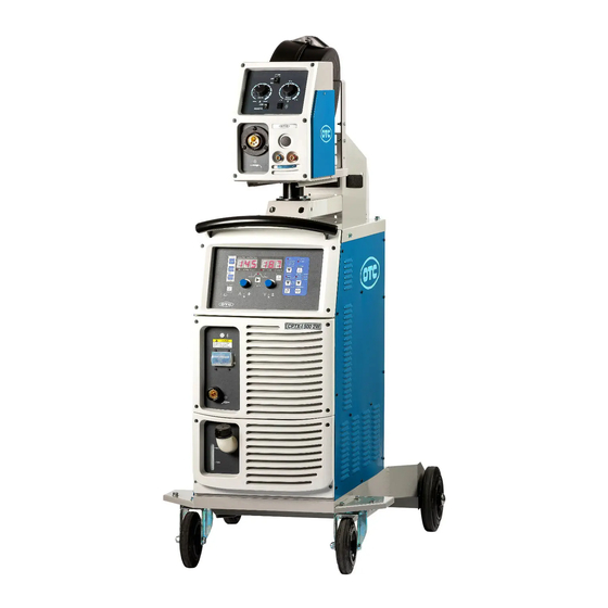
CPTX-I 400 2W
CPTX-I 500 2W
WELDING PRODUCTS DIVISION
MANUAL NO:C1035/C1036-02
MODEL: CPVX-400 C1035
CPVX-500 C1036
August, 2020
Advertisement
Table of Contents

Related Manuals for Daihen OTC CPTX-I 400 2W


Summary of Contents for Daihen OTC CPTX-I 400 2W
- Page 1 Do not allow untrained persons to install, operate or maintain this equipment. Contact your distributor if you do not fully understand this manual. DAIHEN Corporation WELDING PRODUCTS DIVISION Upon contact, advise MODEL and MANUAL NO. August, 2020...
-
Page 2: Table Of Contents
TABLE OF CONTENTS 1. SAFETY INFORMATION ......................2 2. ARC WELDING SAFETY PRECAUTIONS .................. 2 3. GENERAL NOTICE OF OPERATION ..................7 4. STANDARD CONFIGURATION AND ACCESSORIES ............... 9 5. NAME OF EACH PART ....................... 11 6. NECESSARY POWER SOURCE EQUIPMENT ............... 12 7. -
Page 3: Safety Information
1. SAFETY INFORMATION The following safety alert symbols and signal words are used throughout this manual to identify various hazards and special instructions. WARNING gives information regarding possible personal injury or loss WARNING of life. CAUTION refers to minor personal injury or possible equipment CAUTION damage. - Page 4 2. ARC WELDING SAFETY PRECAUTIONS (continued) ELECTRIC SHOCK can kill. Touching live electrical parts can cause fatal shocks or severe burns. The electrode and work circuits are electrically live whenever the output is on. The power line and internal circuits of this equipment are also live when the line disconnect switch is on.
- Page 5 2. ARC WELDING SAFETY PRECAUTIONS (continued) WELDING can cause fire and explosion. Sparks and spatter fly off from the welding arc. The flying sparks, hot metal, spatter, hot base metal and hot equipment can cause fire and explosion. Accidental contact of electrode or welding wire to metal object can cause sparks, overheating, or fire.
- Page 6 2. ARC WELDING SAFETY PRECAUTIONS (continued) CYLINDER can explode if damaged. A shielding gas cylinder contains high-pressure gas. If damaged, a cylinder can explode. Since gas cylinders are normally part of the welding process, be sure to handle them carefully. 1.
- Page 7 2. ARC WELDING SAFETY PRECAUTIONS (continued) WARNING ● Do not alter or remodel our products. ● You may get injured or have your equipment damaged because of fire, failure or malfunction caused by altering or remodeling the products. ● The warranty does not cover any altered or remodeled products PRINCIPAL SAFETY STANDARDS Arc welding equipment –...
-
Page 8: General Notice Of Operation
3. GENERAL NOTICE OF OPERATION 3.1 Rated Duty Cycle CAUTION Use this welding power source at or under the rated duty cycle. Exceeding the rated duty ⚫ cycle limitation may result in damage to the welding machine. Built-up dust on the transistor or the cold plate on the rectifier may affect the ⚫... - Page 9 3. GENERAL NOTICE OF OPERATION (Continued) 3.2 Static External Characteristics This welding power source is constant -voltage source, the static external characteristics as shown in the figure below. CPTX-I 500 2W CPTX-I 400 2W Output Current (A) 3.3 Gas mixture ratio and wire extension Gas mixture ratio has affections to welding, may causing the difference between output and set value.
-
Page 10: Standard Configuration And Accessories
4. STANDARD CONFIGURATION AND ACCESSORIES 4.1 Standard Configuration ⚫ The devices shown in the boxes are standard composition. Other parts must be prepared by the customers. ⚫ Standard cable length is 2/5/10m. You can select extension cable as optional accessary. Please refer to section 11.4.1. - Page 11 4. STANDARD CONFIGURATION AND ACCESSORIES (Continued) 4.3 Items to be Prepared by User (1) Shielding Gas Prepare carbon dioxide or mixed gases (in accordance with the welding method). ⚫ Carbon Dioxide (CO gas) : The CO gas used for welding shall be a conforming product with a purity above 99.5% and a moisture content below 0.05%.
-
Page 12: Name Of Each Part
5. NAME OF EACH PART 5.1 Welding power source ●Name of Each Part of CPTX-I 400/500 2W -11-... -
Page 13: Necessary Power Source Equipment
6. NECESSARY POWER SOURCE EQUIPMENT 6.1 Welding Power Source Equipment (commercial power supply) WARNING ⚫ When the welding machine is used in s uch a humid environment as construction site, on the steel plate, or on steel structure, install a leakage breaker. CAUTION ⚫... -
Page 14: Transport And Installation
7. TRANSPORT AND INSTALLATION 7.1 Transport WARNING Follow the instructions below to avoid accident and product damage when carrying the welding power source. ⚫ Do not touch the live electrical parts inside or outside the welding power source. ⚫ Be sure to disconnect the line disconnect switch before carrying the welding power source. - Page 15 7. TRANSPORT AND INSTALLATION (Continued) CAUTION Follow the instructions below when selecting an installation place for the welding power source. ⚫ Do not install the welding power source in a place subject to direct sunlight and rain. ⚫ Place the welding machine on a strong and stable surface. ⚫...
-
Page 16: Connection Procedure And Ground For Safety Use
8. CONNECTION PROCEDURE AND GROUND FOR SAFETY USE WARNING Follow the instructions below to avoid electric shock. Do not touch the live electrified parts, as this will result in a fatal shock and sever burn. ⚫ Do not touch the live electrical parts of the welding machine. ⚫... - Page 17 8. CONNECTION PROCEDURE AND GROUND FOR SAFETY USE (Continued) For MAG/MIG welding use 8.2.1 Connect in the numerical order. (1) Ground the base metal. (If required by the local law or codes) (2) Connect the welding cable between the base metal and output terminal (base metal⊝) of the power source.
- Page 18 8. CONNECTION PROCEDURE AND GROUND FOR SAFETY USE (Continued) For DC STICK welding use 8.2.2 Connect in the numerical order. (1) Ground the base metal. (If required by the local law or codes) (2) Connect the welding cable between the base metal and output terminal (base metal⊝) of the power source.
- Page 19 8. CONNECTION PROCEDURE AND GROUND FOR SAFETY USE (Continued) 8.3 Connection of the Gas Hose WARNING You may suffer from danger of suffocation caused by lack of oxygen when shield gas keep drifting in a closed place. Be sure to turn off the shield gas at the main when the welding power source is not in use.
- Page 20 8. CONNECTION PROCEDURE AND GROUND FOR SAFETY USE (Continued) 8.4 Grounding and Connecting of Input Power Source WARNING Follow the instructions below to avoid electric shock. Touching the live electrical parts may result in a fatal electric shock and severe burn.
- Page 21 8. CONNECTION PROCEDURE AND GROUND FOR SAFETY USE (Continued) Shell must be grounded MANDATORY Section area: must exceed 6mm². If ungrounded, the inner circuit of the power source can form voltage with ⚫ capacitance between the shell or with stray capacitance(input side conductor and shell metal may form intermetallic).
-
Page 22: Welding Preparation
9. WELDING PREPARATION 9.1 Preparing the Projective Equipment WARNING To protect you and others from gas generated from welding, fumes, and lack of oxygen, wear protective equipment. ⚫ To avoid gas poisoning and danger of suffocation, wear a gas mask or adequately ventilate when the welding machine is used in the place regulated by local law. - Page 23 9. WELDING PREPARATION (Continued) 9.2 Operation of Switches and Controlling the Gas Regulator CAUTION ⚫ Keep your face away from the outlet when turning on gas at the main of the gas cylinder, as a burst of high-pressure gas may result in physical injuries. ※...
- Page 24 (1)Use coolant Please use DAIHEN’S genuine coolant. Because the DAIHEN’S genuine coolant is mixture of the pure water and anti-freeze liquid in special portion to prevent from freezing and rusting due to the germs ※Notice) Please do not use the dirty water, industrial water and low quality coolant. In these cases, the blocking might occur in torch.
- Page 25 9. WELDING PREPARATION (Continued) 9.5 Welding Conditions When setting to the improper welding conditions, the following troubles will occur. Cause Trouble ・Long Arc length ・Wide bead width Wire extension is too long. ・Poor shield current increase ・ Note 1 ・Short arc length Wire extension is too short.
- Page 26 9. WELDING PREPARATION (Continued) 9.5.1 CO Welding conditions for CO (for reference only) (1) Example Welding Conditions of Horizontal Fillet Plate Wire Welding Welding Travel thickness length diameter current voltage speed flow rate t (mm) ℓ (mm) Ø (mm) (cm/min) (L/min) 2.5~3.0 0.9, 1.0...
- Page 27 9. WELDING PREPARATION (Continued) (3) Example Welding Conditions of I Shape Butt without Backing Plate Plate Root Wire Number Welding Welding Travel thickness diameter current voltage speed flow rate t (mm) g (mm) Ø(mm) layers (cm/min) (L/min) 0.9, 1.0 70~80 17~18 45~55 0.9, 1.0...
- Page 28 9. WELDING PREPARATION (Continued) (5) Example Welding Conditions of Lap Fillet 10~15° 25~35° Plate Wire Welding Welding Travel Mark thickness diameter current voltage speed flow rate position Ø (mm) t (mm) (cm/min) (L/min) 0.8~1.0 80~100 18~19 45~55 10~15 0.8~1.2 100~120 18~20 45~55 10~15...
- Page 29 9. WELDING PREPARATION (Continued) 9.5.2 Example Welding Conditions for CO Welding with Flux-cored Wires (1) Example Welding Conditions of Horizontal Fillet Wire Welding Welding Travel length diameter current voltage speed ℓ (mm) (mm) (cm/min) Ø 9.4.3 Example Welding Conditions of MAG Short Arc Material: Soft steel, Gas: Mixture gas 80% Ar+20% CO (10~15 L/min) Plate...
-
Page 30: Operation
10. OPERATION Use ”Quick Manual” in the section 14. For reference. Operation Panel [14] [9] [13] [12] [4] [8] [6] [1] [10][3] [11] [2] GAS select key ARC CONTROL key WIRE TYPE select key SYNERG/INDIV key WIRE DIAMETER select key [10] GAS CHECK key WELDING CURRENT adjusting knob... - Page 31 10. OPERATION (Continued) CAUTION ⚫ This welding machine should be operated by persons only after reading and understanding contents of this owner’s manual and having knowledge and skills for handling the welding machine safely. ⚫ Use this welding power source at or under the rated duty cycle. Exceeding the rated duty cycle limitation may result in damage to the welding machine.
- Page 32 10. OPERATION (Continued) When setting a combination is not existing in the table, abnormality of setting welding method will occur, the digital meter “------” blinks, and the welding power source will stop operation automatically. In addition, the LED corresponding to the wrong wire diameter or shielding gas will also blink. For example, the current welding mode is “SOLID”, “MAG”, “Ø1.0”, when the WIRE TYPE is changed from “SOLID wire”...
- Page 33 10. OPERATION (Continued) 10.1.2 Setting of Parameter Welding voltage can be set directly by Welding current can be set directly by WELDING VOLTAGE adjusting knob [5]. WELDING CURRENT adjusting knob [4]. Select a parameter (display switches clockwise) Part for welding parameter setting Select a welding condition by DISPLAY CHANGE key[7], then the digital meter will display the corresponding condition value selected, and the LED corresponding to the condition will light up simultaneously.
- Page 34 10. OPERATION (Continued) 10.1.3 Setting of Crater Fill Functions A crater is a depression left at the termination point of the Crater weld. As it may cause cracks and welding defects, a crater Bead treatment called crater-filler is used to fill in the depression. Molten Pool When giving a crater treatment, set the CRATER FILLER[6] key to “ON”...
- Page 35 10. OPERATION (Continued) INITIAL CRATER Timing chart condition Torch switch Pre-flow time Anti-stick(burn-back)time No-load Gas flow voltage Post-flow time Welding voltage Slow-down speed Main current Wire feed speed Crater current Welding current Main welding Crater Torch switch Pre-flow time Anti-stick(burn-back)time Gas flow No-load voltage...
- Page 36 10. OPERATION (Continued) INITIAL CRATER Timing chart condition Within 2 secs Torch switch Pre-flow time Post-flow time No-load voltage Gas flow Wedging voltage Slow-down speed Anti-stick(burn-back)time Main current Wire feed speed Crater current Welding current MAIN WELDING CRATER CRATER CRATER Within 2 secs REPEAT Torch switch...
- Page 37 10. OPERATION (Continued) 10.1.4 Setting of Arc Spot Welding To carry out arc spot welding, select the “· · · ·” mode by CRATER FILLER key[6], and set spot welding current by CURRENT adjusting knob[4] and spot welding voltage by VOLTAGE adjusting knob[5].
- Page 38 10. OPERATION (Continued) 10.1.6 Adjustment of Welding Voltage Using the VOLT. CONTROL key[9] allows you to select one of the following voltage adjustment methods. The state of VOLT. CONTROL is changed in the following order each time the key is pressed. INDIVIDUAL→...
- Page 39 10. OPERATION (Continued) 10.1.8 Gas Check ( ) Function This function is used when opening the valve of the shielding gas and when adjusting the gas flow rate. When pressing the GAS CHECK key [10] once, the GAS CHECK lamp lights up and allows gas to flow.
- Page 40 10. OPERATION (Continued) 3) Display of Welding Results After Completion of Welding After completion of welding, the average output current and voltage of the last one second blink for about 20 seconds (however, the output condition of crater filler are ignored). The welding operator can verify the welding conditions according to such display after completion of welding, and such results can also be used as approximate values for condition adjustment.
- Page 41 10. OPERATION (Continued) ● When making the INDIVIDUAL adjustment When “INDIVIDUAL” is set (at the operation panel), welding current and voltage can be set individually. ● When making the SYNERGIC adjustment When the “SYNERGIC” adjustment is set, welding voltage is automatically adjusted only by turning the WELDING CURRENT knob[4].
- Page 42 10. OPERATION (Continued) ● Usage of Internal Function (1) Push and hold down DISPLAY CHANGE key[7] for a few seconds to switch to the internal function mode. The left digital meter will display a function number, and the right digital meter will light up to display the function status corresponding to the function number.
- Page 43 OPERATION (Continued) (2) Fine adjustment of anti-stick(burn-back) Voltage : F2 Anti-stick(burn-back) voltage means the voltage which is output when processing is carried out to prevent wire from sticking to the base metal at the end of welding. Anti-stick(burn-back) voltage is preset to proper conditions according to welding method and wire diameter at shipment, but it can be finely adjusted by setting F2.
- Page 44 OPERATION (Continued) Perform connection according to the figure below for inputting current setting signal and voltage setting signal by means of external voltage. Use a power source with a capacity greater than 0.5mA for E1 and E2. MAX 0.5mA MAX 0.5mA CON2 Welding voltage Welding current...
- Page 45 10. OPERATION (Continued) 10.2.1 Setting of Internal Function (continued) (5) Switch of external setting voltage range: F5 When using this function, the F4 must be set to “1” to switch to “auto” mode. ※ F5:OFF: default factory setting, the external supply voltage range of 0V to 15V. ※...
- Page 46 10. OPERATION (Continued) (8) Setting of result display time: F8 After completion of welding, the average output current and voltage of the last 1 second will be displayed flickeringly for about 20 seconds. Result display time can be set by using “F8”, wherein the left digital meter displays setting value and the “sec”...
- Page 47 10. OPERATION (Continued) (13) Penetration Control function: F13 For conventional CO /MAG welding, as the wire extension changes, welding current changes and base metal penetration depth and bead width change. By setting the PENETRATION CONTROL function to “ON”, wire feed rate is automatically adjusted so that constant current is always obtained even when wire stick-out varies.
- Page 48 10. OPERATION (Continued) (19) Pump energy saving function:F19 Default setting is [OFF]. When welding is finished, the welding machine is in the state of standby, and after around 20 minutes, the pump will stop automatically. The pump will start automatically when the next welding begins. When setting to ON, the pump continue to operate and does not stop when the welding machine stops.(energy saving function stops).
- Page 49 10. OPERATION (Continued) 10.2.3 Password Lock Function The primary purpose of the Key lock is to avoid changing welding conditions accidentally. In other words, everybody can un-lock it easily. On the other hand, this Key Lock with the Password make possible to avoid any change by those who does not know the password. The basic operation is the same as the standard Key Lock.
- Page 50 10. OPERATION (Continued) After switching to the password setting mode, the left digital meter will display “Loc”, the right digital meter will display “000” with the hundreds digit blinking. In this status, the hundreds digit can be set through the parameter adjusting knobs ([4],[5]). For example, the setting method for password “123”...
- Page 51 10. OPERATION (Continued) [2] Method for Releasing a Password Lock (1) When in the password lock state, after long pressing the ENTER key[14] to release the lock, the digital meters will display “PAS PAS” for 2 seconds before switching to the password input mode.
- Page 52 10. OPERATION (Continued) ●Operation Procedure for Password Lock Function Press ENTER key and turn on the power switch simultaneously. Release the Is a password password lock. already set? Set the hundreds digit of password by the parameter setting knobs. Press DISPLAY CHANGE key.
- Page 53 10. OPERATION (Continued) 10.2.4 JOB MEMORY Function The set welding conditions can be stored in the internal memory of the welding power source by using the memory function for welding condition, and the stored data can be read at any time to reproduce the welding conditions.
- Page 54 10. OPERATION (Continued) [1] SAVE Function Welding conditions being currently in use are stored in the JOB MEMORY inside the welding power source. ● Memory Method (1) Press SAVE key [13] to switch to a memory mode. If the specified condition number has memory data stored, the LEDs corresponding to Crater Filler, Welding Method, etc.
- Page 55 10. OPERATION (Continued) [2] LOAD Function To read out the welding conditions stored in the JOB MEMORY of the welding power source. The welding condition being used will be overwritten by the welding Note: condition to be read. Store the current useful welding condition to be used in the future by a condition number before reading.
- Page 56 10. OPERATION (Continued) ● Operation Procedure for Memory Mode Press SAVE key. To cancel Set a condition number by the adjusting knob. Press SAVE key. Press ENTER key. To cancel Confirm parameter value by DISPLAY CHANGE key. Reset a condition number To memorize data by the JOB No.
- Page 57 10. OPERATION (Continued) [3] Deletion of Memory The welding conditions stored can be deleted. You can delete all stored welding conditions at one time or delete them one by one. ● Deletion Method (1) Turn off the power switch, and then turn on the power switch with LOAD key[12] and SAVE key[13] pressed down at the same time.
- Page 58 10. OPERATION (Continued) 10.2.5 Recovery method for Initial Values The welding condition being used (including internal functions) can restore to their initial values completely without any effect to the stored welding conditions. To restore the initial values, first turn off the power switch, then press (keep pressing) DISPLAY CHANGE key [7] and GAS CHECK key[10] at the same time, and then turn on the power switch.
-
Page 59: Applied Function
11. APPLIED FUNCTION WARNING Observe the following to prevent electrical shock. ⚫ Do not touch charging parts inside or outside the welding power source. ⚫ Grounding to the case of the welding power source should be performed by persons qualified electric work and according to the laws and regulations in your area. - Page 60 11. APPLIED FUNCTION (Continued) Signals Name and Functions about 12P Terminal Block Pin No. Signal Name Function READY Terminals for standby signal of welding power source. (output) When there is no Open Phase, Operation Stop, Output Over –(2) Welding Current or Abnormal Temperature and the power switch is ON, this power source signal is valid (internal TR breakover).
- Page 61 11. APPLIED FUNCTION (Continued) 11.2 Combining with an Automatic Machine When combining with an automatic machine, connect the welding power source to an auto-welding machine through external connection using the internal 12P terminal block (TM4), the socket for remote control box and the socket for wire feeder . Refer to section “11.1 External Connection inside Terminal Block”...
- Page 62 11. APPLIED FUNCTION (Continued) 11.3 Auto-stop function of blower Cooling blower can automatically stop 10 minutes after the finishing of welding work and automatically start at next welding work. In addition, when blower is switched on it will begin rotating, but power-saving function will automatically start after 10 minutes of non-operation.
- Page 63 11. APPLIED FUNCTION (Continued) 1)Cable Applicable Remarks Machine Model CPTX-I 400 2W Model 606650 606651 606652 606653 CPTX-I 500 2W 11.4.2 MAG Flow meter (for MAG welding) WARNING ⚫ Use a special MAG gas flow regulator when performing MAG (80% Ar, 20% CO ) welding.
-
Page 64: Maintenance And Troubleshooting
12. MAINTENANCE AND TROUBLESHOOTING WARNING To avoid electric shocks, follow the below instructions. Do not touch the live electrical parts inside or outside the welding machine. ⚫ Turn off all of the line disconnect switches before touching the parts inside the welding ⚫... - Page 65 12. MAINTENANCE AND TROUBLESHOOTING (Continued) 12.1 Carrying out Maintenance on the Welding Power Source Periodically check the welding power source to ensure the safety of the equipment and the efficiency of work. ● Check the following daily: – No strange vibration, buzzing noise, and burning smell are generated from the welding power source.
- Page 66 12. MAINTENANCE AND TROUBLESHOOTING (Continued) 12.2 Precautions for Replacement of the Printed Circuit Board( Continued) 2) Verify that the plug-in numbers printed on the circuit boards are in accordance with those on the bunched wires, and then plug them in place firmly after confirmation. Wrong insertion or connection may damage the circuit boards and even the entire machine.
- Page 67 12. MAINTENANCE AND TROUBLESHOOTINGR (Continued) 12.4 How to Solve an Error WARNING Observe the following to prevent electrical shock. When touching charging parts, critical electric shock and burn may occur. ● Do not touch live electrical parts inside or outside the welding machine. ●...
- Page 68 12. MAINTENANCE AND TROUBLE SHOOTING (Continued) 3) “E-100” blinking -Control power supply error- When the control power source has an abnormality, “E-100” in the display will blink, and the welding power source will automatically stop operation. Check the CN9 on the circuit board P30110P and the connecting wire of the auxiliary transformer, and then turn on the power supply again to remove this abnormality.
- Page 69 12. MAINTENANCE AND TROUBLESHOOTING (Continued) 10) “E-700” blinking - Output Over Current error – If over-current time exceeds the max. value or the secondary side has a continuous short-circuit during welding, “E-700” will be displayed flickeringly, and the welding power source will automatically stop operation.
- Page 70 12. MAINTENANCE AND TROUBLESHOOTING (Continued) 12.5 Troubleshooting When an error code is displayed, refer to Section 12.4“How to solve an error”. Check the troubleshooting information listed below before contacting your dealer for service. ⚫ Trouble (Phenomenon) Cause Solution Never turn it on again. Contact your dealer. The Power switch tripping.
- Page 71 12. MAINTENANCE AND TROUBLESHOOTING (Continued) Trouble Cause of Malfunction and Treatment (Phenomenon) Abnormality Trouble with the inverter main Shut off the power supply and circuit. contact your dealer. After pressing the welding torch switch, gas flows out without no-load voltage. After inspecting P30256P and Trouble with the control circuit.
- Page 72 12. MAINTENANCE AND FAULT REPAIR (Continued) 12.6 Schematic diagram -71-...
- Page 73 12. MAINTENANCE AND TROUBLE SHOOTING (Continued) 12.7 Parts Layout Front Panel Back Panel PCB1 PCB2 PCB5 R1~4 C5~8 PCB3 PCB6 Over chassis -72-...
- Page 74 12. MAINTENANCE AND TROUBLE SHOOTING (Continued) PCB4 (5) Right Side Left Side R5,6 THP1(Below) R7,8 Inverter Primary Circuit -73-...
- Page 75 12. MAINTENANCE AND TROUBLE SHOOTING (Continued) Inverter Secondary Circuit Inverter Secondary Circuit (CPTX-I 400 2W) (CPTX-I 400 2W) -74-...
-
Page 76: Parts List
13. PARTS LIST 13.1 Parts List ● Please contact your dealer to order parts. (See the back cover for telephone number, fax number, and mailing address.) 1) Parts list for power source CPTX-I CPTX-I 400 2W 500 2W Symbol DV Code Part No. - Page 77 PARTS LIST (Continued) CPTX-I CPTX-I 400 2W 500 2W Symbol DV Code Part No. Description Specification Amount Amount R9,10 606908 100-0858 CEMENT RESISTOR RX27N-4V-40W-5.1RJ 606909 100-0672 CEMENT RESISTOR RX27-4V-40W-1R-J 606910 QW-W00160 TRANSFORMER QW-W00160 606911 QW-W00152B TRANSFORMER QW-W00152B 606912 QW-W00123 TRANSFORMER QW-W00123 606913 QW-W00128...
-
Page 78: Specifications
14. SPECIFICATIONS 14.1 Specifications Product Name CPTX-I 400 2W CPTX-I 500 2W Number of phases Rated frequency 50/60Hz 50/60Hz Rated input voltage 400V 400V Input voltage range 400V±10% 400V±10% 23.0KVA 22.0KW Rated input 16.2KVA 15.4KW Rated input current 24.6A 36.2A Rated output current 400A 500A... - Page 79 14. SPECIFICATIONS (Continued) 14.2 External View 1520 -78-...
- Page 80 14. SPECIFICATIONS (Continued) 14.3 Initial Value and Setting Range ● Initial Value and Setting Range of Parameters Setting range Initial value CPTX-I 400 2W CPTX-I 500 2W Current 100 A 30–450A 30-550A ·Initial condition ·Main welding condition Voltage 19 V 12–45V 12-50V ·Crater-fill condition...
- Page 81 14. SPECIFICATIONS (Continued) The operation time of pump after welding 20 – 60 min finish Pump save energy function ON (valid) / OFF(invalid) ● Operation panel [14] [9] [13] [12] [4] [8] [6] [1] [10][3] [11] [2] GAS select key WIRE TYPE select key WIRE DIAMETER select key CURRENT adjusting knob...
- Page 82 14. SPECIFICATIONS (Continued) ● Quick manual Refer to Section 10.1 “Basic Settings” and Section 10.2 “Applied setting” for detailed setting. Note: Turn the knob to the right to increase value, or Before Using the Welding Power Source ⚫ to the left to decrease value. In addition, faster rotational speed will make the increment or 1.
- Page 83 Storage of Welding Condition 1) Press the SAVE key to switch to Press the LOAD key a memory mode. The right display meter will display a condition Set the welding condition number Discontinue number and the left display meter by the adjusting knob. will display the welding current stored by the condition number.
-
Page 84: Service And Support
15. SERVICE AND SUPPORT Please contact your dealer for service. (See the back cover for telephone number, fax number, and mailing address.) Note: See section“12. MAINTENANCCE AND TROUBLE SHOOTING” before contacting your dealer for service. When contacting your dealer for service, you are required to provide the following information: Name ⚫... - Page 85 Phone: +1-937-667-0800, Fax: +1-937-667-0885 OTC DAIHEN EUROPE GmbH Krefelder Strasse 677, D-41066 Mönchengladbach, Germany Phone: +49-2161-694970, Fax: +49-2161-6949761 DAIHEN VARSTROJ welding cutting and robotics d.d. Industrijska ulica 4, 9220 Lendava - Lendva, Slovenija Phone: +386-25-788-826, Fax: +386-25-751-277 OTC Industrial (Shanghai) Co.,Ltd.
Need help?
Do you have a question about the OTC CPTX-I 400 2W and is the answer not in the manual?
Questions and answers