Table of Contents
Troubleshooting

Related Manuals for Daihen Welbee WB-A350P


Summary of Contents for Daihen Welbee WB-A350P
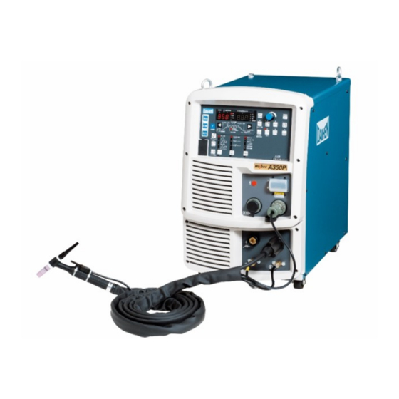
- Page 1 Welding power source A350P Welbee Inverter OWNER'S MANUAL Model: WB-A350P Ensure to read this instruction manual thoroughly for safe and proper use of the product. October , 2018 Manual No. : P30249-2 DAIHEN Corporation...
-
Page 3: Forward
Preliminaries Forward Thank you for your purchase of OTC's welding power source. This Owner's Manual (hereafter referred to as "this manual") explains the following points for safe use of the product. • Caution regarding the product • Welding operation/setting method •... -
Page 4: Important Information
Important Information Use of the Product This product is a power supply unit designed and manufactured for use in arc welding. Do not use the product for any other purposes. Safe Use of the Product For safe use of the product (hereafter referred to as welding power source), ensure to follow the instructions below: •... -
Page 5: Service And Support
Service and Support See the back cover for contact numbers and mailing addresses. When contacting your dealer for service, you are required to provide the following information: • Name, address, telephone number • Product model, manufacture year, serial number, and software version number (Refer to the diagram below for product information. -
Page 6: Table Of Contents
ABLE OF ONTENTS TABLE OF CONTENTS CHAPTER 4 CONNECTION Forward ........i Important Information. - Page 7 ABLE OF ONTENTS 6.6 Setting Welding Conditions ..6-13 8.5 Insulation Resistance Measurement and Withstand Voltage Test....8-6 6.6.1 Setting welding parameter .
- Page 8 ABLE OF ONTENTS (MEMO)
-
Page 9: Chapter 1 Safety Information
Chapter 1 Safety Information This chapter explains the precautions on the welding power source and welding operation. 1.1 Warning Symbols The following safety warning symbols and signs are used throughout the manual to ensure proper operation of the product and to prevent from various hazards that cause serious injury and damages. Indication and explanation for the symbols are as follows: Make sure to fully understand the content before beginning operation. -
Page 10: Precautions For Power Supply And Electric Shock
HAPTER AFETY NFORMATION AFETY RECAUTION • For those with pacemaker, avoid being close to the machine during operation or work area until obtaining physician's approval. Machine at operation will generate magnetic field nearby that may cause influence upon the working of pacemaker. •... -
Page 11: Precautions For Air Discharge And Use Of Respiratory Protective Equipment
HAPTER AFETY NFORMATION AFETY RECAUTION 1.2.3 Precautions for air discharge and use of respiratory protective equipment To prevent suffocation or gas poisoning in the welding operation, ensure to follow the instructions below: • When welding is required in tank, boiler, reaction tower, or hold of a ship, closed space, or any other places of poor ventilation, ensure to provide ventilation equipment. -
Page 12: Precautions For Flammable Materials
HAPTER AFETY NFORMATION AFETY RECAUTION 1.2.4 Precautions for flammable materials To prevent fire, explosion and rupture, ensure to follow the instructions below: • Remove all flammables within 10 m (33 ft) of the welding arc so that sparks and spatter do not strike flammable materials. If this is not possible, tightly cover them with noncombustible covers. -
Page 13: Precautions For Gas Cylinder And Gas Regulator
HAPTER AFETY NFORMATION AFETY RECAUTION 1.2.5 Precautions for gas cylinder and gas regulator To prevent falling of gas cylinder, gas regulator explosion and accident caused by gas, ensure to follow the instructions below: • Use only correct shield gas cylinders according to the related laws, regulations and customer's standard. -
Page 14: Precautions For Disassembling And Modifying The Welding Power Source
HAPTER AFETY NFORMATION AFETY RECAUTION 1.2.7 Precautions for disassembling and modifying the welding power source To prevent electrical shock, fire, injury from malfunction and error in the welding power source, ensure to follow the instructions below: • Do not disassemble/modify the welding power source. Disassembling/modifying by customer is out of the warranty scope. -
Page 15: Precautions For High-Frequency Wave
HAPTER AFETY NFORMATION AFETY RECAUTION 1.2.10 Precautions for high-frequency wave Observe the following safety measures to avoid the electromagnetic interference: • Note that the following facilities or equipment nearby may cause high-frequency wave to invade and cause electromagnetic interferences: Input cable, signal cable, phone cable; Radio, television;... -
Page 16: Principal Safety Standards
HAPTER AFETY NFORMATION RINCIPAL AFETY TANDARDS 1.3 Principal Safety Standards Arc welding equipment – Installation and use, Technical Specification IEC 62081, from International Electro technical Commission Arc welding equipment Part 1: Welding power sources IEC 60974-1, from International Electro technical Commission Safety in Welding and Cutting, ANSI Standard Z49.1, from American Welding Society. -
Page 17: Chapter 2 Product Specification And Configuration
Chapter 2 Product Specification and Configuration This chapter explains the specification, name of each parts and configuration of the welding power source. 2.1 Specification This section explains the specification and external dimension of the welding power source. 2.1.1 Specifications This chapter explains the specification of the welding power source. Welbee Inverter A350P Specification/Model AC TIG welding... -
Page 18: External Dimensions
HAPTER RODUCT PECIFICATION AND ONFIGURATION PECIFICATION 2.1.2 External dimensions This section explains the external dimensions of the welding power source. 15.6" (395 mm) 28.0" (710 mm) 14mm 12.6" 18.1" (460 mm) 3.9" (100 mm) (320 mm) 2.1.3 Rated duty cycle This section explains the rated duty cycle of the welding power source. -
Page 19: Product Configuration
HAPTER RODUCT PECIFICATION AND ONFIGURATION RODUCT ONFIGURATION • Use the welding power source within its usable range by observing the duty cycle for the welding current. • Use the welding power source within the lowest rated duty cycle of combined accessories such as welding torches. <Relationship between welding current and duty cycle>... -
Page 20: Accessory (Supplied)
HAPTER RODUCT PECIFICATION AND ONFIGURATION RODUCT ONFIGURATION Welding power source Base metal Ground a base metal if required by local law. Supplied unit Optional Name Remarks (*1) accessories To be prepared by the customer. Gas regulator 2.2.3 Accessory (not supplied)) ○... -
Page 21: Accessory (Not Supplied)
HAPTER RODUCT PECIFICATION AND ONFIGURATION RODUCT ONFIGURATION 2.2.3 Accessory (not supplied) This section explains the accessories to be prepared by the customer before operating the welding power source. Prepare the following: • Gas regulator For the gas regulator, make sure to use a device for compressed gas cylinder that conforms to the specific application of the shield gas. - Page 22 HAPTER RODUCT PECIFICATION AND ONFIGURATION RODUCT ONFIGURATION 2.2.4.2 Welding torch Model AWD-17 AWD-26 AWD-18 150 A 200 A 350 A Rated current 130 A 160 A 270 A Cooling method Air-cooled Air-cooled Water-cooled Rated duty cycle 50 % 50 % 100 % 0.5 mm to 0.5 mm to...
- Page 23 HAPTER RODUCT PECIFICATION AND ONFIGURATION RODUCT ONFIGURATION • Extension cables, hoses, etc. (for torch) Item name Part No. Q'ty Remarks Extension torch cable H954B00 13.1 ft (4 m) BAWE-1504 Torch switch control cable (2-core) P1043S00 13.1 ft (4 m) Part for extending the cable length [13.1 ft (4 m)] of AW (P)-17 torch to Adapter P1600N02...
- Page 24 HAPTER RODUCT PECIFICATION AND ONFIGURATION RODUCT ONFIGURATION • Connection method to use by extending torch cable – For water-cooled torch: Connect the hoses and cables of the optional accessories as follows. * Be careful not to connect the water supply hose and the condensate hose oppositely. * See the instruction manual of the cooling water circulation device (PU-701) when using the cooling water circulation device (PU-701).
- Page 25 HAPTER RODUCT PECIFICATION AND ONFIGURATION RODUCT ONFIGURATION 2.2.4.5 Tungsten electrode Use the tungsten electrode with 2% ceria (marked in gray) or the tungsten electrode with 2% lantana (marked in yellow). For AC TIG welding, the pure tungsten electrode (marked in green) can also be used. Select the diameter of the electrode depending on the welding current, referring to the table below.
- Page 26 HAPTER RODUCT PECIFICATION AND ONFIGURATION RODUCT ONFIGURATION 2.2.4.6 Dedicated connector (base metal side) Use this connector to connect the cable (base metal side) and the cable (STICK welding holder side) with the welding power source. Type Part No. Applicable cable diameter Rated current DIXSKK50/70 4734-025...
-
Page 27: Part Names
HAPTER RODUCT PECIFICATION AND ONFIGURATION AMES 2.3 Part Names This section explains the part names of the welding power source. 2.3.1 Front panel The section explains the front section of the welding power source. Operation panel 6.2 Function on Operation Panel) Main power lamp Power switch Socket for analog remote control... - Page 28 HAPTER RODUCT PECIFICATION AND ONFIGURATION AMES 2-12...
-
Page 29: Chapter 3 Transportation And Installation
Chapter 3 Transportation and Installation This chapter explains the necessary equipment, installation environment and transportation method for installing the welding power source. 3.1 Required Equipment This section explains the necessary power supply equipment for installing the welding power source and equipment for preventing lack of oxygen and dust hazard during welding. -
Page 30: Ventilation Equipment/Partial Exhaust Facility
HAPTER RANSPORTATION AND NSTALLATION EQUIRED QUIPMENT 3.1.1.1 Use of the engine generator and auxiliary power • To prevent the welding power source from being damaged or arc loss, follow the instructions below. When using an engine generator for the welding power source, pay attention to the following. •... -
Page 31: Installation Environment
HAPTER RANSPORTATION AND NSTALLATION NSTALLATION NVIRONMENT 3.1.2.2 Partial exhaust facility To prevent any health damage due to poisonous gas or particle substances (fume) emitted in the welding operation, provide partial exhaust facility. • When it is difficult to provide a partial exhaust facility or the ventilation or exhaust facility does not give sufficient performance, ensure to use the respiratory protective equipment. -
Page 32: Electromagnetic Interference
HAPTER RANSPORTATION AND NSTALLATION RANSPORTATION ROCEDURE 3.2.2 Electromagnetic interference To prevent electromagnetic troubles, read the following. Also, if electromagnetic troubles occur, check the following again. • Change the installation place of the welding power source. • Mount an input cable in the grounded metallic conduit. •... -
Page 33: Transportation With Lifting Lug
HAPTER RANSPORTATION AND NSTALLATION RANSPORTATION ROCEDURE 3.3.1 Transportation with lifting lug This section explains the procedure for transportation with lifting lug such as a crane. For preventing falling of the welding power source and resulting accidents, be sure to observe the following: •... -
Page 34: Manual Transportation With Carts
HAPTER RANSPORTATION AND NSTALLATION RANSPORTATION ROCEDURE 3.3.2 Manual transportation with carts This section explains the manual procedure for transportation using equipment such as a cart. • When lifting the welding power source, make sure to hold the bottom of the welding power source by more than one person. -
Page 35: Chapter 4 Connection
Chapter 4 Connection This chapter explains the procedure for connecting the welding power source. 4.1 Precautions for Connection Procedure and Grounding This section explains the precautions for connection and grounding procedure. For protection from serious injury or fire, observe the following: For protection from electric shock, observe the following points: •... -
Page 36: Connecting The Welding Power Source
HAPTER ONNECTION ONNECTING THE ELDING OWER OURCE 4.2 Connecting the Welding Power Source This section explains the procedure for connecting the welding power source. Follow the steps below for connection of the welding power source. • Do not turn on the input power of the welding power source until confirming the completion of connection work. -
Page 37: Connection Of Cable (Base Metal Side)
HAPTER ONNECTION ONNECTING THE ELDING OWER OURCE 4.2.1 Connection of cable (base metal side) This section explains the procedures for connecting the base metal side cable. In order to connect the base metal side cable with the welding power source, a dedicated connector must be installed at the end of the base metal side cable. -
Page 38: Connection Of Tig Welding Torch
HAPTER ONNECTION ONNECTING THE ELDING OWER OURCE 4.2.2 Connection of TIG welding torch This section explains the connection procedures for the TIG welding. Torch switch Torch switch cable Condensed water hose Torch power Fix with attached bands cable Torch switch Welding power source Torch... - Page 39 HAPTER ONNECTION ONNECTING THE ELDING OWER OURCE 4.2.2.1 Precautions for connections for AC TIG welding When using the welding power source for AC TIG welding, keep the cable as short as possible. If you really need to use an extension cable, use caution on the following points. •...
- Page 40 HAPTER ONNECTION ONNECTING THE ELDING OWER OURCE Divide surplus cables to A and B and wind them in the same manner, times of winding, and diameter. Top view Side view Pile the bundle A on the bundle B. Pile them so that their winding directions are opposite. ●...
-
Page 41: Connection Of Dc Stick Welding Torch
HAPTER ONNECTION ONNECTING THE ELDING OWER OURCE 4.2.3 Connection of DC STICK welding torch This section explains the connection procedures for the STICK welding. Prepare a welding rod holder. ( 2.2.3 Accessory (not supplied)) NOTE • A dedicated connector must be installed at the end of the cable on the STICK welding holder side. -
Page 42: Connection Of Shield Gas
HAPTER ONNECTION ONNECTING THE ELDING OWER OURCE 4.2.4 Connection of shield gas This section explains the procedure for connecting the the shield gas. • Be sure to observe the following points to prevent from suffocation due to gas leakage or explosion. –... -
Page 43: Connection Of Water Hose With Cooling Water Circulation Device
HAPTER ONNECTION ONNECTING THE ELDING OWER OURCE 4.2.5 Connection of water hose with cooling water circulation device This section explains the procedure to connect the cooling water circulation device and the water hose. Also, refer to the instruction manual of the cooling water circulation device. •... -
Page 44: Grounding And Connection Of
HAPTER ONNECTION ROUNDING AND ONNECTION OF NPUT OWER UPPLY 4.3 Grounding and Connection of Input Power Supply This section explains the procedure for performing grounding work, connecting the welding power source and input power supply (power supply at facility side). •... -
Page 45: Confirmation Of Connection
HAPTER ONNECTION ONFIRMATION OF ONNECTION 4.4 Confirmation of Connection This section explains the point of confirmation after completing all of the connections. Check for the following after the connection is complete. • No looseness in the cable connections If looseness is found, tighten it to secure the connection. •... -
Page 46: Connection Of Voltage Reducing Device
HAPTER ONNECTION ONNECTION OF OLTAGE EDUCING EVICE 4.5 Connection of Voltage Reducing Device 4.5.1 Installation to welding power source This section explains the procedure for installing the voltage reducing device to the welding power source. Eye bolts Mounting bracket Spring washer Hexagonal nut Hexagonal bolt (M8 ×... -
Page 47: Connection Of Output Cable
HAPTER ONNECTION ONNECTION OF OLTAGE EDUCING EVICE 4.5.2 Connection of output cable This section explains the procedure for connecting the output cable. NOTE • The welding rod holder, the cable (welding rod holder side), and the cable (base metal side) must be prepared by the customer. -
Page 48: Grounding And Connection Of Input Cable
HAPTER ONNECTION ONNECTION OF XTERNAL QUIPMENT 4.5.3 Grounding and Connection of Input Cable This section explains the procedure for performing grounding work and input cable. • When voltage reducing device and the welding power source are used in a humid environment such as construction site, or location with highly conducting material such as steel plate or on steel structure, install a leakage breaker. - Page 49 HAPTER ONNECTION ONNECTION OF XTERNAL QUIPMENT 4.6.1.1 Wiring for connecting external equipment The welding power source is equipped with terminal block for external connection inside the cover for external connection at the rear. When connecting to the automatic machine, use this terminal block for external connection.
- Page 50 HAPTER ONNECTION ONNECTION OF XTERNAL QUIPMENT • Output signal of the external connection terminal block Welding power Output signal is open collector output. Ensure to keep the source side maximum rated power of the transistor. Maximum rated power of transistor READY: DC50 V/100 mA OUT EXT1 to 4: DC50 V/100 mA Transistor...
- Page 51 HAPTER ONNECTION ONNECTION OF XTERNAL QUIPMENT • The control cable drawn out from the terminal for external connection should be kept away from the welding power cable or the torch cable as much as possible. Otherwise, failure may occur due to noise during use. •...
- Page 52 HAPTER ONNECTION ONNECTION OF XTERNAL QUIPMENT 4-18...
-
Page 53: Chapter 5 Welding Operation
Chapter 5 Welding Operation This chapter explains the procedures from preparation to completion of the welding operation. 5.1 Precaution at Welding Operation This section explains the safety precautions for welding operation. 5.1.1 Precautions for air discharge and use of respiratory protective equipment To prevent suffocation or gas poisoning in the welding operation, ensure to follow the instructions below:... -
Page 54: Precaution For Protective Equipment
HAPTER ELDING PERATION RECAUTION AT ELDING PERATION 5.1.2 Precaution for protective equipment For protection from arc ray generated from welding, spatter and spattering dross and hearing disorder from noise, observe the following: • Wear safety goggles with sufficient blocking effect or face shield in the work area and the surrounding. -
Page 55: Precautions For High-Frequency Wave
HAPTER ELDING PERATION HECK BEFORE ELDING 5.1.4 Precautions for high-frequency wave Observe the following safety measures to avoid the electromagnetic interference: • Note that the following facilities or equipment nearby may cause high-frequency wave to invade and cause electromagnetic interferences: Input cable, signal cable, phone cable;... -
Page 56: Power On And Gas Supply
HAPTER ELDING PERATION OWER UPPLY 5.3 Power ON and Gas Supply This section explains how to supply power and shield gas. • Handle the gas cylinder according to the related laws or regulations as well as the internal standard of the customer. Note that the gas cylinder contains a high-pressure gas. -
Page 57: Check And Setting Of Welding Condition
HAPTER ELDING PERATION HECK AND ETTING OF ELDING ONDITION Turn the flow rate adjustment knob to "OPEN", and adjust the flow rate of shield gas. Press the GAS CHECK key. The LED of the GAS CHECK key lights off, to stop gas check. ⇒... -
Page 58: Performing Welding Operation
HAPTER ELDING PERATION ERFORMING ELDING PERATION 5.4.2.2 Deactivating erroneous operation prevention function Press and hold the ENTER key for approximately three seconds or more again. The LED of the ENTER key lights off, which deactivates the erroneous operation prevention function. ⇒... -
Page 59: Operation During Welding
HAPTER ELDING PERATION ERFORMING ELDING PERATION 5.5.2 Operation during welding This section explains the operation to adjust the welding current as necessary during welding. Welding current can be adjusted during each sequence (initial current, welding current, or crater current) TIPS •... -
Page 60: Operation At Welding End
HAPTER ELDING PERATION ERFORMING ELDING PERATION 5.5.3 Operation at welding end This section explains the supply stop procedure of power/shield gas after the welding end. Main valve GAS CHECK key Flow rate Welding power adjustment knob source SHUT Shut off Power switch Welding power source... -
Page 61: Chapter 6 Welding Condition
Chapter 6 Welding Condition This chapter explains the functions on the operation panel as well as how to set the welding conditions. 6.1 List of Welding Conditions This section explains the parameters/functions settable in the welding power source. 6.1.1 Parameter (Welding parameter) Parameter Set Range Initial Value... -
Page 62: Function
HAPTER ELDING ONDITION IST OF ELDING ONDITIONS 6.1.2 Function Function Initial value Setting parameter CRATER-FILL OFF/ON/ON (repeat)/Arc Spot Welding method AC TIG/AC-DC TIG/DC TIG/AC STICK/DC STICK AC TIG AC waveform Standard Standard/Soft/Hard Initial current ON/OFF Lift start ON/OFF Pulse ON/OFF Slope ON/OFF Torch current... - Page 63 HAPTER ELDING ONDITION IST OF ELDING ONDITIONS Function Name Setting range Initial value Explanation Memory You can switch operation as follows when Pulse is set ON and the current adjustment function by the torch switch is enabled. Switchover of current 1: Changes pulse current only without changing adjustment operation at 1 to 2...
- Page 64 HAPTER ELDING ONDITION IST OF ELDING ONDITIONS Function Name Setting range Initial value Explanation Memory Sets the static characteristics in AC STICK welding AC STICK welding - mode. switchover of OFF/ON — OFF: Constant voltage characteristics characteristics ON: Drooping characteristics AC STICK welding - Set the current change amount when switchover of adjustment of drooping...
- Page 65 HAPTER ELDING ONDITION IST OF ELDING ONDITIONS Function Name Setting range Initial value Explanation Memory Arc loss detection time Arc start error detection time WCR output ON Used when connecting with automatic machine OFF (fixed) — delay time made by other manufacturer. WCR output OFF delay time Analog setting switch...
-
Page 66: Function On Operation Panel
HAPTER ELDING ONDITION UNCTION ON PERATION ANEL 6.2 Function on Operation Panel This section explains the function of displays and keys arranged on the operation panel. DC NO-LOAD VOLTAGE WARNING V/Φ SYNERG. FREQ. sec. JOB No. WELD PULSE FREQ. UP SLOPE DOWN SLOPE MONITOR AC BALANCE... - Page 67 HAPTER ELDING ONDITION UNCTION ON PERATION ANEL Name Function Sets the welding time when "ARC SPOT" is selected by the CRATER-FILL key. ( 6.6.5 spot time) SPOT TIME key Pressing this key makes the LED lit, enabling to adjust the welding time by the parameter adjustment knob.
-
Page 68: Welding Conditions
HAPTER ELDING ONDITION ELDING ONDITIONS 6.3 Welding Conditions This section explains basic welding conditions with useful functions. 6.3.1 Basic welding conditions This section explains the basic welding conditions. To carry out the welding operation, the followings should be considered: • Plate thickness and materials of welding material •... -
Page 69: Preparing Welding Conditions
HAPTER ELDING ONDITION REPARING ELDING ONDITIONS 6.4 Preparing Welding Conditions This section explains the setting process of basic welding conditions. Check welding material suitable for the welding condition 10.3 Materials for Setting Welding Conditions) ↓ Start setting 6.6.2 Start setting (Touch/High-frequency)) ↓... -
Page 70: Memory Registration Of Welding Conditions
HAPTER ELDING ONDITION EMORY UNCTION OF ELDING ONDITIONS NOTE • When the analog remote control (option) is connected, the set values of the analog remote control apply to the welding current (base current) and pulse current values of the main welding condition even if the registered welding condition is loaded. -
Page 71: Read Out Of Welding Conditions
HAPTER ELDING ONDITION EMORY UNCTION OF ELDING ONDITIONS Press the ENTER key. The welding condition is registered with the selected JOB No., and the storage function mode is ⇒ terminated. The registered welding condition can be read out for use. 6.5.2 Read out of welding conditions This section explains how to read out the welding conditions registered in the memory. -
Page 72: Deletion Of Memory Registration
HAPTER ELDING ONDITION EMORY UNCTION OF ELDING ONDITIONS Press the ENTER key. The welding condition is registered with the selected JOB No., and the read mode is terminated. ⇒ The registered welding condition can be loaded to use for operation. 6.5.3 Deletion of memory registration This section explains how to delete the welding conditions registered to the memory. -
Page 73: Setting Welding Conditions
HAPTER ELDING ONDITION ETTING ELDING ONDITIONS Press the ENTER key. The welding condition of the selected JOB No. is ⇒ deleted, and "End" is displayed on the right/left WARNING DC NO-LOAD VOLTAGE digital meters. Φ sec. JOB No. Check that "End" is displayed on the left/right digital meters and turn off the power switch. The power LED switch goes off. -
Page 74: Start Setting (Touch/High-Frequency)
HAPTER ELDING ONDITION ETTING ELDING ONDITIONS 6.6.1.2 Welding parameter setting This section explains how to set the welding parameters (gas discharge time, welding current) according to the welding sequence. Parameter adjusting knob DC NO-LOAD VOLTAGE WARNING V/Φ SYNERG. FREQ. sec. JOB No. - Page 75 HAPTER ELDING ONDITION ETTING ELDING ONDITIONS Press the torch switch while the electrode is apart from the base metal. High frequency sparks fly to generate arc between the base metal and the electrode. NOTE • If arc does not start within five seconds after high frequency sparks begin to fly, generation of high frequency sparks and output voltage will stop automatically.
-
Page 76: Crater Setting
HAPTER ELDING ONDITION ETTING ELDING ONDITIONS 6.6.3 Crater setting This section explains the details of crater treatment and torch switch operation. There are modes listed below for the crater setting. For initialization current, select availability by the INITIAL CURRENT SELECT key. Mode Initial condition Description... - Page 77 HAPTER ELDING ONDITION ETTING ELDING ONDITIONS 6.6.3.2 Crater “ON” (no initial current) Select "CRATER-FILL ON" with the CRATER-FILL key to turn off the LED of the INITIAL CURRENT key. • Carry out twice the ON/OFF operation of the torch switch and carry out the welding operation. In the second ON operation, the welding sequence is carried out by the crater current.
-
Page 78: Slope Setting
HAPTER ELDING ONDITION ETTING ELDING ONDITIONS 6.6.3.4 CREATER-FILL ON (repeat) Select "CRATER-FILL ON (repeat)" with the CRATER-FILL key. • During welding, welding is self-held even after the torch switch is turned off. Turning on the torch switch again switches the welding sequence to the crater treatment. During the crater treatment, the torch switch has to be held on. -
Page 79: Arc Spot Time
HAPTER ELDING ONDITION ETTING ELDING ONDITIONS 6.6.5 Arc spot time This section explains the details of arc spot and torch switch operation. Selecting "ARC SPOT" by the CRATER-FILL key allows the machine in the main mode. • Once current flows with the torch switch turned on, the current continues to flow during the Arc Spot period (including the down-slope time in the Slope ON mode) even after the torch switch is turned off. -
Page 80: Pulse Setting
HAPTER ELDING ONDITION AC TIG W AC-DC TIG W ETTINGS FOR ELDING AND ELDING 6.6.6 Pulse setting It is called "Pulse" to change the welding current periodically for the purpose to stabilize arc, control penetration shape, and control heat input. Pulse aims at solidifying arc and increasing arc stability in the large current period, and controls penetration shape and heat input by the small and large current ratio. -
Page 81: Functions Of Ac Tig Welding And Ac-Dc Tig Welding
HAPTER ELDING ONDITION AC TIG W AC-DC TIG W ETTINGS FOR ELDING AND ELDING 6.7.1 Functions of AC TIG welding and AC-DC TIG welding This is a TIG welding method that takes full advantage of the bipolar characteristics of the “+” electrode which obtains cleaning action and the “-”... -
Page 82: Setting Cleaning Width
HAPTER ELDING ONDITION AC TIG W AC-DC TIG W ETTINGS FOR ELDING AND ELDING 6.7.4 Setting cleaning width Set the strength of the cleaning action during AC TIG welding. When either one of the initial condition, welding condition and crater condition is selected, press the CLEANING WIDTH key. -
Page 83: Setting Ac-Dc Switchover Frequency
HAPTER ELDING ONDITION AC TIG W AC-DC TIG W ETTINGS FOR ELDING AND ELDING 6.7.5 Setting AC-DC switchover frequency Set the AC-DC switchover frequency for AC-DC TIG welding. When either one of the initial condition, welding condition and crater condition is selected, press the AC- DC SWITCHOVER FREQUENCY key. -
Page 84: Adjusting Current With Torch Switch
HAPTER ELDING ONDITION DJUSTING CURRENT WITH TORCH SWITCH 6.8 Adjusting current with torch switch The welding current may be increased or decreased by the torch switch operation. Turn ON/OFF this function with the TORCH CURRENT ADJUSTMENT key. The LED at the upper left of the key is lit when this function is "ON". -
Page 85: Welding Setting Guide
HAPTER ELDING ONDITION ELDING ETTING UIDE 6.9 Welding Setting Guide The Welding Setting Guide is a function in which the welding machine automatically determines appropriate welding conditions such as (Welding current, Initial current (when initial current is selected), Crater current (when CRATER-FILL ON is selected), Pre-flow time and Post-flow time, and Up-slope time and Down-slope time) by selecting the electrode diameter, the base metal material, the weld joint shape, and the base metal plate thickness. -
Page 86: Details Of Welding Setting Guide
HAPTER ELDING ONDITION ELDING ETTING UIDE Repeat the operations in Steps 2 and 3 to set the set values of setting item Nos. (S1-S4). Tap the WELDING SETTING GUIDE key. Appropriate each parameter value the welding machine has determined based on the set values is ⇒... -
Page 87: Revising And Exiting Welding Setting Guide
HAPTER ELDING ONDITION ELDING ETTING UIDE 6.9.2.4 S4: Base metal plate thickness The plate thickness of the base metal can be set by setting the left digital meter to "S4". The plate thickness can be set in 0.1 mm unit and the setting range is determined as follows depending on the set base metal material and welded joint. -
Page 88: Affixing Guide Plate For Welding Settings
HAPTER ELDING ONDITION ETTING NTERNAL UNCTIONS 6.9.4 Affixing guide plate for welding settings Affix the guide plate for welding settings as shown below. DC NO-LOAD VOLTAGE WARNING V/Φ SYNERG. FREQ. sec. JOB No. WELD PULSE FREQ. UP SLOPE DOWN SLOPE MONITOR AC BALANCE INITIAL CURR. - Page 89 HAPTER ELDING ONDITION ETTING NTERNAL UNCTIONS Depress the F (Function) key for one second or more. The function No. is displayed on the left digital ⇒ meter in a flashing mode. The setting value of each function No. is displayed ⇒...
-
Page 90: Detailed Information On Internal Functions
HAPTER ELDING ONDITION ETTING NTERNAL UNCTIONS 6.10.2 Detailed information on internal functions This section explains the detailed information of internal functions in the order of function No. 6.10.2.1 F1: Fine-adjustment of starting current Fine-adjusts the starting current at the time of TIG welding start. The output value of the starting current can be adjusted in the range of 10 to 200%, assuming the standard starting current as 100%. - Page 91 HAPTER ELDING ONDITION ETTING NTERNAL UNCTIONS 6.10.2.2 F2: Chenge in sequence at arc spot This function can break arc even in the Arc Spot period when the torch switch is set to "OFF" in the Arc Spot mode. When this function is set to "ON" (enabled), hold the torch switch ON during the Arc Spot process. •...
- Page 92 HAPTER ELDING ONDITION ETTING NTERNAL UNCTIONS 6.10.2.4 F4: Auto/Manual mode When using the welding power source with a robot and/or automated machine, the I/O (interface) of the welding power source can be set to be suited for the application. In the settings "0" to "2", the welding sequence will be as follows. The settings "3" and "4" are for the modes only for our robot.
- Page 93 HAPTER ELDING ONDITION ETTING NTERNAL UNCTIONS 6.10.2.5 F5: Maximum external command voltage Set the maximum value of the voltage command inputted from the outside when using the welding power source by setting the internal function F4 (Auto/Manual mode) to "1" (Automatic machine 1 mode).
- Page 94 HAPTER ELDING ONDITION ETTING NTERNAL UNCTIONS 6.10.2.7 F7: Pulse peak ratio adjustment This function sets the ratio of the pulse width in one cycle during pulse output. Set the peak time (pulse width) to the pulse cycle shown in the figure below by the percentage. •...
- Page 95 HAPTER ELDING ONDITION ETTING NTERNAL UNCTIONS 6.10.2.12 F12: Current increase and decrease by double-clicking This function sets the current increase or decrease value by double-clicking when the welding current is increased or decreased by the torch switch operation. This function is available when the TORCH CURRENT ADJUSTMENT key is set to "ON".
- Page 96 HAPTER ELDING ONDITION ETTING NTERNAL UNCTIONS 6.10.2.17 F17: Switchover of memory condition interlocking function (when connected with the filler control device) When connected with the filler control device (HC-71D), welding condition memory function of the welding power source and the wire feed condition memory function of the filler control device can be interlocked, shearing the memory condition number.
- Page 97 HAPTER ELDING ONDITION ETTING NTERNAL UNCTIONS 6.10.2.22 F23: Sleep mode switching time When the welding power source is not operated for a fixed period of time, it can be turned into the sleep mode. • [0]: disables the function. • [1] to [10]: enables the function. Set the transition time to the sleep mode in the range of 1 to 10.
- Page 98 HAPTER ELDING ONDITION ETTING NTERNAL UNCTIONS 6.10.2.24 F29 to F32: External input terminal setting Set the function of external input terminals. (when using robot or automatic machines) • F29: set the function of IN-EXT1 ("5" to "9") on the external connection terminal block TM3. •...
- Page 99 HAPTER ELDING ONDITION ETTING NTERNAL UNCTIONS The external input terminal without the setting "3" is regarded as signal OFF. Accordingly, for the function (external input terminal) which does not require the "ON" status for the JOB No. to read can be set to other functions. Example 1) In reading out the welding condition of the JOB No.3;...
- Page 100 HAPTER ELDING ONDITION ETTING NTERNAL UNCTIONS • Before 100 ms of the torch switch ON (start signal "ON"), set the welding condition to "3" for F29 to F32 to read out the welding JOB No. • To switch plural signals at the same time, carry out the operation within 40 ms. •...
- Page 101 HAPTER ELDING ONDITION ETTING NTERNAL UNCTIONS 6.10.2.28 F36: STICK welding torch switch function Enables to start and stop welding with the torch switch in the AC STICK welding mode and DC STICK welding mode. Since the no-load voltage is output when the torch switch is pressed, arc is started by contacting the welding rod with the base metal when no-load voltage output is being output.
- Page 102 HAPTER ELDING ONDITION ETTING NTERNAL UNCTIONS 6.10.2.31 F39/F40: Current display adjustment (Gain/offset) Set the adjustment value (gain/offset) when the current display value on the left digital meter is different from the actual current value. The current value displayed on the digital meter is obtained by software processing of the average value of outputs;...
- Page 103 HAPTER ELDING ONDITION ETTING NTERNAL UNCTIONS 6.10.2.34 F44: Reading welding conditions with remote control Sets whether to read the welding condition registered to the memory by the analog remote control (optional) or not. This function is effective when the internal function F4 (Auto/Manual mode) is set to "0".
- Page 104 HAPTER ELDING ONDITION ETTING NTERNAL UNCTIONS 6.10.2.35 F45/F46/F47: Special crater sequence (effective/initial standard time setting/ crater standard time setting) Incorporates initial condition and crater condition in the "No crater" sequence. • Setting the internal function F45 to [ON] enables to carry out the initial welding/crater treatment set by F46/F47 even in the welding of "No crater"...
- Page 105 HAPTER ELDING ONDITION ETTING NTERNAL UNCTIONS 6.10.2.37 F49: Setting of current value (initial current) The current value of the initial current can be set in percentage based on the current value of the welding condition. • Setting range of current value (initial current): 10 % to 300 % 6.10.2.38 F50: Setting of current value (crater current) The current value of the crater current can be set in percentage based on the current value of the welding condition.
- Page 106 HAPTER ELDING ONDITION ETTING NTERNAL UNCTIONS 6.10.2.43 F61: Fine adjustment of electrode formation Fine adjusts the shape of the electrode tip in the electrode formation function. Fine-adjust the formation time by the grinding angle of the electrode. • If the grinding angle is sharp, set to negative. •...
-
Page 107: Operation Of Analog Remote Control (Optional)
HAPTER ELDING ONDITION PERATION OF NALOG EMOTE ONTROL PTIONAL 6.11 Operation of Analog Remote Control (Optional) This section explains the functions of knobs and buttons arranged for the analog remote controller (optional) as well as their operation. Since the setting at the analog remote control is preferred when connected, it is not possible to set this condition on the operation panel of welding power source. - Page 108 HAPTER ELDING ONDITION PERATION OF NALOG EMOTE ONTROL PTIONAL 6-48...
-
Page 109: Chapter 7 Administrator Functions
Chapter 7 Administrator Functions This chapter explains the functions used by administrators such as protection and initialization of welding conditions. 7.1 Protection of Welding Conditions This chapter explains the protection function (password function) of welding conditions. When the function is enabled, 5.4.2 Preventing erroneous operation on operation panel (Erroneous operation prevention function)a password will be requested to disable the erroneous operation prevention... - Page 110 HAPTER DMINISTRATOR UNCTIONS ROTECTION OF ELDING ONDITIONS Turn off the power switch. Press and hold the F (function) key and the ENTER key simultaneously and turn on the power switch. Hold the two keys pressed down until "Loc" is ● displayed on the left digital meter.
-
Page 111: Disabling Erroneous Operation Prevention
HAPTER DMINISTRATOR UNCTIONS ROTECTION OF ELDING ONDITIONS 7.1.2 Disabling erroneous operation prevention This section explains how to disable the password-protected erroneous operation prevention function. • To change the input of the password on the way, move the digit position by pressing the [ ] or [ ] key. •... -
Page 112: Welding Result Control Function
HAPTER DMINISTRATOR UNCTIONS ELDING ESULT ONTROL UNCTION 7.2 Welding Result Control Function This section explains about the welding result control function. The function enables the management of the items below. Welding control Monitor Initial Setting range Explanation parameter value Cumulative number of welding points (number of times) Number of welding 0 to 999 Target value of welding points (number of times) -
Page 113: Details Of Welding Control Items
HAPTER DMINISTRATOR UNCTIONS ELDING ESULT ONTROL UNCTION With the parameter adjusting knob and the WELD MONITOR key, select the desired monitor No. Turning the parameter adjusting knob will change ● the tens place digit of monitor No. (Example: "P10" - >... - Page 114 HAPTER DMINISTRATOR UNCTIONS ELDING ESULT ONTROL UNCTION Set value Operation The count value is cleared when the target is achieved (*1) Operation is continued after the target is achieved (*2) Enable Enable Enable Enable Disabled Disabled The count value is cleared when the power is turned on *1: When an alarm is displayed, pressing any key of the operation panel can also clear the count value.
- Page 115 HAPTER DMINISTRATOR UNCTIONS ELDING ESULT ONTROL UNCTION • P33 (Setting of voltage upper limit) • P34 (Setting of voltage lower limit) Set the allowable tolerance range of the welding voltage from 0 to 100V. • P35 (WARNING judgment time) Set the time to judge an event as an error in the range from 0 to 100 seconds when the average current/ voltage (average per second) during welding is outside the allowable tolerance range.
- Page 116 HAPTER DMINISTRATOR UNCTIONS ELDING ESULT ONTROL UNCTION 7.2.2.5 Alarm indication at the time of WARNING detection (Welding Monitor "P35" "P36") If the average current or average voltage becomes out of the specified range, the difference between the average value and the specified value will flash. •...
-
Page 117: Data Backup (Utilization Of Data)
• There is software allowing you to easily display waveforms and edit welding conditions. You can download it from our home page. URL: http://www.daihen.co.jp/products/welder/software/en.html 7.3.1 Setting of welding conditions/internal functions The following contents can be stored in the "DAIHEN_OTC_WELDING_PRAMETER.CSV" file. - Page 118 HAPTER DMINISTRATOR UNCTIONS ACKUP TILIZATION OF DATA Parameter of JOB No.1 Parameter value "-" is shown for unused JOB Nos. Column Item Description Unit Column Item Description Unit -255 to Welding setting job_num JOB No. 155, syn_uslp_tim guide 0.1 (s) 1 to 100 Up-slope time Welding setting...
-
Page 119: Simplified Data Log Function
HAPTER DMINISTRATOR UNCTIONS ACKUP TILIZATION OF DATA Column Item Description Unit Column Item Description Unit Welding setting guide TS click current 0/1 (OFF/ syn_s1_dia 1 ( ) TsCrickIset S1: Electrode adjustment diameter Current increase/ Welding setting decrease syn_s2_mtrl guide CriIsetStep1 0.1 (A) (*4) value by single- S2: Material... -
Page 120: Failure Log Function
HAPTER DMINISTRATOR UNCTIONS ACKUP TILIZATION OF DATA The data types/sampling speed should be specified in the internal function F52/F53 (data log function). ( 6.10 Setting Internal Functions) Simplified data log will be created below the "DAIHEN_OTC_Welbee\DAT\DAT00001" folder. A csv file will be created per welding. When DAIHEN_OTC_Welbee\DAT\DAT00001 folder is already existing, "DAT00002"... -
Page 121: Welding Result Control Function
HAPTER DMINISTRATOR UNCTIONS ACKUP TILIZATION OF DATA 7.3.4 Welding Result Control Function The following contents can be saved in the file "DAIHEN_WELDING_MONITOR_DATA_MACHINE_***.CSV ". • Welding machine identification Number • Cumulative values of Welding result control function The values of internal function F77(Welding result control function identifications numbers) enters into "***"... -
Page 122: Importing Backup Data
HAPTER DMINISTRATOR UNCTIONS ACKUP TILIZATION OF DATA Turn the parameter adjusting knob counterclockwise to display "USb" on the left digital meter. Select the data to back up. Turn the parameter adjusting knob further ● counterclockwise to display the data to backup on the right digital meter. -
Page 123: Initializing Welding Conditions And Internal Functions
HAPTER DMINISTRATOR UNCTIONS NITIALIZING ELDING ONDITIONS AND NTERNAL UNCTIONS Press the SAVE key. The LED of SAVE key lights up. ⇒ SAVE SAVE Turn the parameter adjusting knob counterclockwise to display "USb" on the left digital meter. Select the data to import. Turn the parameter adjusting knob further ●... -
Page 124: Checking Software Version
HAPTER DMINISTRATOR UNCTIONS HECKING OFTWARE ERSION Turn off the power switch. Press and hold the F (function) key and GAS CHECK key simultaneously and turn on the power switch. Hold the two keys pressed down until "End" is ● displayed on the left/right digital meters. Initialization starts. -
Page 125: Chapter 8 Maintenance And Inspection
Chapter 8 Maintenance and Inspection This chapter explains the daily and periodical inspection of the welding power source. 8.1 Precautions for Maintenance and Inspection This section explains the precautions for maintenance and inspection work. To prevent electric shock or burn injury, ensure to follow the instructions below: •... - Page 126 HAPTER AINTENANCE AND NSPECTION RECAUTIONS FOR AINTENANCE AND NSPECTION To prevent damage and problem of the welding power source and loss of the data, ensure to follow the instructions below: • The welding conditions (electronic data) stored by this function are susceptible to occurrence of static electricity, impact, repair, etc., and there is a possibility that the stored contents may be changed or lost.
-
Page 127: Daily Inspection
HAPTER AINTENANCE AND NSPECTION AILY NSPECTION 8.2 Daily Inspection This chapter explains the daily inspection of the welding power source. Perform daily inspection for the following items in the table. Front and rear panel of the welding power source is made from polycarbonate resin. To prevent from electric shock or fire caused by the damage on polycarbonate resin, ensure to follow the instructions below. -
Page 128: Periodical Inspection
HAPTER AINTENANCE AND NSPECTION ERIODICAL NSPECTION 8.3 Periodical Inspection This section explains the periodical inspection of the welding power source. Check the items in the table below every three (3) to six (6) months. • Before performing maintenance and inspection, read the instructions in "8.1 Precautions for Maintenance and Inspection"... -
Page 129: Periodical Replacement Parts
HAPTER AINTENANCE AND NSPECTION ERIODICAL EPLACEMENT ARTS 8.4 Periodical Replacement Parts This section explains the parts to be replaced periodically. • Printed circuit board PCB7 ( 10.1 Parts List) The printed circuit board PCB7 inside the welding power source has a high voltage electrolysis capacitor. The high voltage electrolysis capacitor supplies stable direct current to the inverter circuit, but its performance will degrade year by year. -
Page 130: Insulation Resistance Measurement And Withstand Voltage Test
HAPTER AINTENANCE AND NSPECTION NSULATION ESISTANCE EASUREMENT AND ITHSTAND OLTAGE 8.5 Insulation Resistance Measurement and Withstand Voltage Test If insulation resistance measurement and withstand voltage test is necessary, please contact your dealer. • The customer MUST NOT perform the withstand voltage test. If withstand voltage test is necessary, ensure to contact your dealer. -
Page 131: Chapter 9 Troubleshooting
Chapter 9 Troubleshooting This chapter explains the typical troubleshooting for the welding power source. The cause of problems can be categorized as below: • Mechanical problems (e.g., problems of driving mechanism of the filler wire feeder) • Electric and control problems •... - Page 132 HAPTER ROUBLESHOOTING CTION IN ASE OF RROR Error code Error cause Action and how to cancel error 000 There is no load between the • Identify the cause of no load between the STOP terminals (3-4) of the terminal STOP terminals (*1) block TM3 for external connection.
-
Page 133: Troubleshooting
HAPTER ROUBLESHOOTING ROUBLESHOOTING Error code Error cause Action and how to cancel error Temperature of re-ignition • Leave it untouched (with the power on), operate the cooling fan for 10 control circuit has exceeded minutes or more, and then turn OFF the power switch. allowable range. - Page 134 HAPTER ROUBLESHOOTING ROUBLESHOOTING Problem Possible cause Corrective action Connection of the torch cable is Securely connect the torch cable. loose. The torch switch is broken. Check that the torch switch works normally. High-frequency discharge occurs, but arc is not generated. Electrode has turned in white.
-
Page 135: Chapter 10Reference Materials
Chapter 10 Reference Materials This chapter contains the parts list of welding power source, and reference materials for setting the welding conditions. 10.1 Parts List This section shows the parts list of welding power source. • When placing an order, provide your dealer with the necessary information: the model name of welding power source, the name of the part to be replaced, and the part number (or specifications if part has no number). - Page 136 HAPTER EFERENCE ATERIALS ARTS Code Part No. Product Name Specifications Q’ty Remarks R20 to 23 4508-317 Carbon resistor RD1/2S 3k J 4509-038 Fixed Metal Oxide Film Resistor RS3B 200k 100-3131 Cement resistor 20XXL 20kOHMJ 1 4509-704 Carbon resistor RD1/4W 1k J 4504-944 Winding resistor KNP1W 10 J 100-1430...
-
Page 137: Reference Drawing
HAPTER EFERENCE ATERIALS EFERENCE RAWING • Analog remote control (K5023L00) parts list (Optional) Code Part No. Product Name Specifications Qʼty R29, 30 4501-039 Variable resistor RV24YN20SB 5K 100-0487 Carbon resistor RD20S 12 J 4730-005 Metal connector plug DPC25-4A 4735-007 Knob K-2195 (Large) 3361-655 Cosmetic screw N-3 M5 L = 10 (Black) 10.2 Reference Drawing This section contains the schematic diagram and the parts layout drawing of the welding power source. -
Page 138: Schematic Diagram
HAPTER EFERENCE ATERIALS EFERENCE RAWING 10.2.1 Schematic diagram 10-4... - Page 139 HAPTER EFERENCE ATERIALS EFERENCE RAWING 10-5...
-
Page 140: Parts Layout Drawing
HAPTER EFERENCE ATERIALS EFERENCE RAWING 10.2.2 Parts layout drawing 10-6... -
Page 141: Materials For Setting Welding Conditions
HAPTER EFERENCE ATERIALS ATERIALS FOR ETTING ELDING ONDITIONS 10.3 Materials for Setting Welding Conditions This section provides reference information for setting the welding conditions. 10.3.1 Guide for changing welding conditions This section gives examples of the problems that can occur due to improper welding conditions. Problem Symptom •... - Page 142 HAPTER EFERENCE ATERIALS ATERIALS FOR ETTING ELDING ONDITIONS 10.3.2.1 TIG welding condition (for reference) • General TIG welding condition (used with Pulse set to "OFF".) 90° Electrode Number Thickness Filler wire Current Argon gas flow rate Bevel Material diameter [in. (mm)] [in.
- Page 143 HAPTER EFERENCE ATERIALS ATERIALS FOR ETTING ELDING ONDITIONS Electrode Number Thickness Filler wire Current Argon gas flow rate Bevel Material diameter [in. (mm)] [in. (mm) ] [CFH (L/min)] shape [in. (mm) ] layers 20ga. 0 to 1/16" (0 to 1/16" (1.6) 50 to 60 0.18 to 0.21 (5 to 6) (a), (b)
- Page 144 HAPTER EFERENCE ATERIALS ATERIALS FOR ETTING ELDING ONDITIONS – For welded joint with different heat capacity Pulse condition Travel Filler wire Number speed feed speed Pulse Base Pulse Material Joint shape Frequency [IPM [IPM current current width layers (Hz) (cm/min)] (cm/min)] Copper 23.6 (60)
- Page 145 HAPTER EFERENCE ATERIALS ATERIALS FOR ETTING ELDING ONDITIONS AC TIG pulse welding conditions • Pulse condition Filler wire Thickness Pulse Base Pulse Diameter Feed speed Material Joint shape Frequency [in. [IPM [in. (mm)] current current width (Hz) (mm)Φ] (cm/min)] 20ga. 1/16"...
- Page 146 HAPTER EFERENCE ATERIALS ATERIALS FOR ETTING ELDING ONDITIONS Welding condition table when thickness of plates are different (for reference only) • Mild steel – T fillet joint Plate thickness (1) Plate thickness (2) Plate thickness (2) Welding current Filler wire dia. Argon flow rate [in.
- Page 147 HAPTER EFERENCE ATERIALS ATERIALS FOR ETTING ELDING ONDITIONS – Butt joint Plate thickness (1) Plate thickness (2) Plate thickness (2) Welding current Filler wire dia. Argon flow rate [in. (mm)] [in. (mm)] [in. (mm)] [in. (mm) ] [CFH (L/min)] 20ga. (1.0) 16ga.
- Page 148 HAPTER EFERENCE ATERIALS ATERIALS FOR ETTING ELDING ONDITIONS • Stainless steel – T fillet joint Plate thickness (1) Plate thickness (2) Plate thickness (2) Welding current Filler wire dia. Argon flow rate [in. (mm)] [in. (mm)] [in. (mm)] [in. (mm) ] [CFH (L/min)] (1.5) 3/32"...
- Page 149 HAPTER EFERENCE ATERIALS ATERIALS FOR ETTING ELDING ONDITIONS – Lap joint Plate thickness (1) Plate thickness (2) Plate thickness (2) Welding current Filler wire dia. Argon flow rate [in. (mm)] [in. (mm)] [in. (mm)] [in. (mm) ] [CFH (L/min)] 20ga. (1.0) 16ga.
- Page 150 HAPTER EFERENCE ATERIALS ATERIALS FOR ETTING ELDING ONDITIONS – Corner joint Plate thickness (1) Plate thickness (2) Plate thickness (2) Welding current Filler wire dia. Argon flow rate [in. (mm)] [in. (mm)] [in. (mm)] [in. (mm) ] [CFH (L/min)] 20ga. (1.0) 16ga.
Need help?
Do you have a question about the Welbee WB-A350P and is the answer not in the manual?
Questions and answers