Table of Contents
Advertisement
Available languages
Available languages
Quick Links
MOTOCOLTIVATORE
SERIE 280
Prima di iniziare ad operare con la macchina, leggere attenta-
mente le istruzioni per l'uso.
Before starting to work with the machine, operation read the
instructions for use.
(F.I.)
IT
USO E MANUTENZIONE
EN
OPERATING AND MAINTENANCE
ISTRUZIONI ORIGINALI
con traduzioni delle istruzioni originali
Cod. 18711903
Advertisement
Chapters
Table of Contents

Related Manuals for Fort 280 Series


Summary of Contents for Fort 280 Series
- Page 1 MOTOCOLTIVATORE SERIE 280 (F.I.) USO E MANUTENZIONE OPERATING AND MAINTENANCE Prima di iniziare ad operare con la macchina, leggere attenta- ISTRUZIONI ORIGINALI mente le istruzioni per l’uso. con traduzioni delle istruzioni originali Before starting to work with the machine, operation read the Cod.
- Page 2 Fig. 1...
- Page 3 Fig. 2 0,5 - 2 mm Fig. 3 Fig. 4 Fig. 5 Fig. 6...
- Page 4 Fig. 9 Fig. 7 Fig. 8...
- Page 5 Fig. 10 USO E MANUTENZIONE ..................6 USE AND MAINTENANCE ...................21...
-
Page 6: Table Of Contents
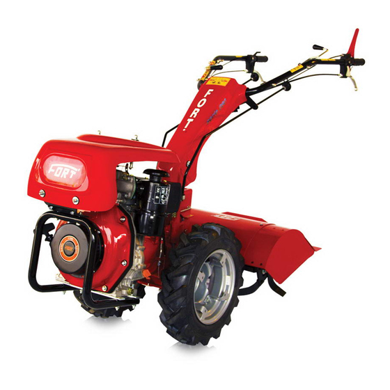
ITALIANO INDICE DESCRIZIONE FIGURE Fig. 1 - Vista d’insieme del motocoltivatore. 1) Targhetta di identificazione. SEZIONE 1. Descrizione e caratteristiche della 2) Gruppo propulsore. Per le sue caratteristiche, macchina vedere libretto di istruzioni allegato. 1.1 Presentazione ........... 7 3) Cambio di velocità. 4) Ruote motrici. 1.2 Garanzia ............7 5) ... -
Page 7: Presentazione
Ditta 1.1 PRESENTAZIONE Costruttrice. Questo manuale riporta le informazioni, le istruzioni e quanto ritenuto necessario per la conoscenza, il buon 1.2 GARANZIA uso e la normale manutenzione del motocoltivatore La Ditta Costruttrice garantisce i suoi prodotti nuovi modello «280», in seguito chiamata anche macchina, di fabbrica per un periodo di 12 (dodici) mesi dalla prodotta dalla «FORT» di Sossano (Vicenza) Italia, in data di acquisto. seguito chiamata anche Ditta Costruttrice. Il motore è garantito secondo condizioni e termini Quanto riportato non costituisce una descrizione com- stabiliti dal Costruttore dello stesso. pleta dei vari organi nè una esposizione dettagliata del Verificare, all’atto del ricevimento, che la macchina loro funzionamento, l’utilizzatore però troverà quanto sia integra e completa. -
Page 8: Identificazione Della Macchina
ITALIANO sori o applicazioni non forniti o testati dalla Ditta prima di qualsiasi intervento o utilizzo della stessa Costruttrice; (anche prima del disimballaggio). - qualora, in seguito a riparazioni eseguite dall’utente senza il consenso della Ditta Costruttrice o a causa 1.4 DESCRIZIONE DELLA MACCHINA E del montaggio di pezzi di ricambio non originali, IMPIEGO PREVISTO la macchina dovesse subire variazioni e il danno Il motocoltivatore modello «280» è una macchina dovesse essere imputabile a tali variazioni; marcata «CE» in conformità con le norme dell’Unio- - qualora non fossero state seguite le istruzioni ne ... -
Page 9: Impiego Non Previsto Della Macchina
ITALIANO L’operatore inoltre, deve utilizzare la macchina mobili e dispositivi di sicurezza. La Ditta Costrut- tenendo presente le norme vigenti in materia di trice pertanto declina ogni responsabilità nel caso prevenzione infortuni, condizioni di utilizzo e ca- di danni provocati in seguito alla manomissione dei ratteristiche della macchina stessa. -
Page 10: Sicurezza
ITALIANO Frizione: multidisco a secco con comando alle SEZIONE 2 stegole. Sicurezza e prevenziones Trasmissione: ad ingranaggi in bagno d’olio Cambio: - 3 marce avanti + 3 RM (versione fresa) 2.1 SICUREZZA - 3 marce avanti + 3 RM (versione falce) L’addetto deve essere istruito sui rischi derivanti da Presa di forza: indipendente con attacco rapido. infortuni, sui dispositivi predisposti per la sicurezza Senso di rotazione P.T.O.: orario (versione fresa) dell’operatore e sulle regole antinfortunistiche generali antiorario (versione falce) previste dalle direttive e dalla legislazione del Paese Dispositivi di sicurezza: di utilizzo della macchina. Nel realizzare la macchina, - Frizione speciale di sicurezza che consente i movi- sono state previste tutte le potenziali situazioni di menti della macchina e l'azionamento degli utensili ... -
Page 11: Norme Di Sicurezza Generali
ITALIANO la macchina. 2.2 SEGNALI DI SICUREZZA • CENTRO DI ASSISTENZA AUTORIZZATO: Il Centro La macchina è stata realizzata adottando tutte le possibili di Assistenza autorizzato è la struttura, legalmente soluzioni per la salvaguardia e la sicurezza di chi vi opera. autorizzata dalla Ditta Costruttrice, che dispone Nonostante ciò la macchina può presentare rischi resi- di personale specializzato e abilitato ad effettuare dui; quei rischi cioè che non è stato possibile eliminare tutte le operazioni di assistenza, manutenzione e completamente in certe condizioni di utilizzo. riparazione, anche di una certa complessità, che Questi potenziali rischi vengono indicati sulla mac- si rendono necessarie per il mantenimento della china ... -
Page 12: Trasporto
ITALIANO è obbligatorio l’uso di indumenti protettivi, guanti esigenze definite dalla Ditta Costruttrice. Usare antitaglio, scarpe antiscivolo e antischiacciamento. esclusivamente ricambi originali. - Rispettare le leggi in vigore nel Paese in cui viene - Quando si opera su terreni cedevoli, in prossimità utilizzata la macchina, relativamente all’uso ed allo di scarpate, fossati o su terreni in pendenza, proce- smaltimento dei prodotti impiegati per la pulizia e dere con la massima cautela e a bassa velocità, per la manutenzione. Smaltire eventuali rifiuti speciali evitare l’eventuale ribaltamento della macchina. tramite le apposite ditte autorizzate allo scopo con - Qualora la macchina fosse destinata ad operare rilascio della ricevuta dell’avvenuto smaltimento. in prossimità di strapiombi pericolosi, è tassati- - È assolutamente vietato azionare o far azionare la vamente obbligatorio, prima di iniziare il lavoro, macchina da chi non ha letto ed assimilato quanto ... -
Page 13: Prima Dell'uso
ITALIANO In caso di immagazzinaggio, non sovrapporre più di Prima di effettuare il caricamento verificare che all’in- tre imballi dello stesso tipo (1+2). terno del cassone del mezzo di trasporto vi sia spazio Evitare di porre sopra il singolo imballo un carico su- sufficiente per accogliere la macchina da trasferire. periore ai 200 Kg (con base di appoggio non inferiore a quella dell’imballo stesso). Per esigenze di trasporto, la macchina viene con- PERICOLO segnata con le stegole posizionate sopra il cofano L’area su cui si intende caricare la macchina, deve motore, le leve innesto presa di forza e selezione essere in piano per evitare possibili spostamenti marce ... -
Page 14: Regolazione Delle Stegole
ITALIANO 4.1.1 REGOLAZIONE DELLE STEGOLE 4.1.2 RUOTE Se la macchina viene consegnata imballata, le stegole La macchina viene fornita con una coppia di ruote che di guida sono poste sopra il motore. possono essere a disco fisso o con disco registrabile Per l’utilizzo, regolarle in altezza e posizionarle in a seconda di quanto richiesto dal cliente. Solitamente funzione all’attrezzatura da applicare ed alla statura le ruote non sono montate sulla macchina. dell'operatore. Per montare le ruote, è necessario: Regolazione in altezza: - Sollevare la macchina (vedi cap. «3.1 Traspor- Spingere verso il basso la leva (13 Fig. 1) e mantenerla to»). in posizione di sbloccaggio, regolare le stegole all’al- - Introdurre le ruote sull'albero (4 Fig. 3) - una per tezza voluta, quindi rilasciare la leva e fare inserire il ... -
Page 15: Verifiche Preliminari
ITALIANO - Sollevare la leva (1 Fig. 6) e verificarne il corretto trollare sempre: scatto di bloccaggio (il fermo deve abbassarsi di - che l’olio motore sia a livello (vedere libretto di 7-8 mm e la leva rimanere sollevata). istruzioni motore); - Quando si azionerà per la prima volta la presa - che il filtro aria motore sia pulito; di forza, dopo aver sostituito un’attrezzatura, - che nel serbatoio vi sia sufficiente carburante. azionare molto lentamente la leva di comando Per il tipo di carburante, fare riferimento al libretto ... -
Page 16: Avanzamento - Innesto Marce
ITALIANO 4) Portarsi a lato della macchina, afferrare il Se dopo più tentativi il motore non si avvia, rivol- manettino della cordicella di avviamento motore gersi al servizio assistenza. (14 Fig. 1) e tirare lentamente fino a quando non Durante il lavoro, impugnare saldamente le stegole si riscontra una certa resistenza. A questo punto per evitare che la macchina possa sfuggire di mano tirare con uno strappo forte e deciso. -
Page 17: In Lavoro
ITALIANO avanti a retromarcia; quindi per movimentare la su tratti inclinati poichè lo spostarsi del baricentro macchina in retromarcia, azionare la leva di co- da una parte all’altra può creare sobbalzi al mezzo, mando frizione come descritto al paragrafo 4.3. compromettendone così l’equilibrio. - Accelerare, con cautela, fino al regime di giri desi- derato. 4.4.2 STAZIONAMENTO - Per interrompere la retrocessione rilasciare la leva frizione. ATTENZIONE Evitare assolutamente di stazionare il veicolo su ATTENZIONE terreni cedevoli, in vicinanza di scarpate, fossati o EVITARE NEL MODO PIù... -
Page 18: Arresto Del Motore
ITALIANO Innesto e disinnesto Una macchina pulita e ben tenuta darà sempre il Per inserire la presa di forza, procedere nel seguente massimo della resa. modo: - Con leva di comando frizione libera e macchina SEZIONE 5 ferma, portare il motore al minimo di giri agendo Manutenzione ordinaria sulla leva acceleratore (9 Fig. 1). - Tirare o spingere l’asta (12 Fig. 1) a seconda della posizione in cui si trova. 5.1 GENERALITà - Abbassare molto lentamente la leva di comando Per come è stato concepito, il motocoltivatore, non ... -
Page 19: Regolazione Comando Frizione
ITALIANO tuzione dell’olio del cambio (usare esclusivamente 5.4 MANUTENZIONE STRAORDINARIA olio EP320). Le operazioni di manutenzione straordinaria non sono La sostituzione deve essere fatta a macchina calda, contemplate in questo manuale: devono comunque facendo defluire l’olio usato dal foro di scarico (2 Fig. essere effettuate esclusivamente dalla Ditta Costrut- 3) posto sotto la macchina. trice o da personale specializzato e autorizzato dalla Terminato lo scarico dell’olio, rimettere il tappo di stessa. scarico ed inserire il nuovo olio nella quantità di 1,3 kg attraverso il foro del tappo (3 Fig. 3). Dopo 5.5 MESSA A RIPOSO l’immissione e anche periodicamente, controllare il ... -
Page 20: Possibili Inconvenienti E Loro Soluzione
ITALIANO 5.8 POSSIBILI INCONVENIENTI E LORO C) La macchina fatica ad avanzare o ha poca resa alla PTO: RISOLUZIONE 1) Controllare la distanza tra vite di controllo e la leva; A) Il motore non parte: eseguire nell’ordine i seguenti eventualmente registrarla come descritto al punto controlli: 5.3.1. 1) che il livello del carburante raggiunga almeno la 2) Controllare che l’accessorio sia inserito corretta- metà del serbatoio; mente nell’attacco rapido della PTO. 2) che il rubinetto del carburante sia aperto e che 3) ... - Page 21 ENGLISH DESCRIPTION OF FIGURES TABLE OF CONTENTS Figure 1 - Overview of the tiller. 1) Nameplate. SECTION 1. Description and specifications of the 2) Power unit. Due to its characteristics, see the in- machine struction manual attached. 1.1 Foreword. ............22 3) Transmission. 1.2 Warranty ............22 4) Drive wheels. 5) Steering handles. 1.2.1 ...
-
Page 22: Section 1. Description And Specifications Of The Machine
The engine is warranted in compliance with the terms the mower, model «280», hereinafter also called and conditions established by the Manufacturer machine or vehicle, manufactured by «FORT» from himself. Sossano (Vicenza), Italy, hereinafter also referred to We suggest checking the integrity of the machine as Manufacturer. when you receive it. What is herewith written is neither a complete descrip- Any claim shall be made in writing within 8 (eight) ... -
Page 23: Identification Of The Machine
ENGLISH tested by the Manufacturer were assembled on the an integral part of the machine and they must be machine; carefully read before carrying out any intervention or - in case, further to repairs carried out by the user before using it (even before unpacking it). without the Manufacturer’s permission or in case, due to the assembly of non-genuine spare parts, 1.4 DESCRIPTION OF THE MACHINE AND the machine undergoes changes and the damage AUTHORIZED USE is attributable to such changes: The mower model «280» is a machine «EC» marked - in case the instructions listed in this manual are in compliance with the regulations of the European not complied with; Union listed in the Directive 2006/42/EC, 2004/108/ - if some exceptional events should happen. EC, as described in the declaration of conformity at- Moreover, the warranty does not include the damages tached to each machine. resulting form negligence, carelessness, bad use and ... -
Page 24: Unauthorized Use Of The Machine
ENGLISH 1.4.2 UNAUTHORIZED USE OF THE MACHINE laboratory in compliance with the EN ISO 3746/1996 Standard and the recorded levels were the follow- ing: DANGER - THE MACHINE SHALL NOT BE USED IN ENVIRON- ENGINE Sound pressure Sound MENTS WHERE VAPORS OR EXPLOSIVE FLAM- level at the power level MABLE GAX MIXTURES MAY DEVELOP driver's seat LwA (dB) directive... -
Page 25: Safety
ENGLISH Safety devices: operator’s safety and on the general accident preven- - A special safety clutch that makes the machine tion regulations provided for by the legislation of the movements and work tool operation possible by Country where the machine is being used. means of a non-release lever positioned on the While designing the machine, all the potential danger- handlebars (7 Fig.1). When this lever is released, ous situations were foreseen and consequently the all the machine functions stop without turning the proper protections were adopted. Anyhow, the level engine off. of accidents caused by the careless and improper use - The clutch control lever has a special automatic of the machine is still high. -
Page 26: General Safety Regulation
ENGLISH operations, also the most difficult ones, which are conditions of use. necessary for perfectly maintaining the machine These potential hazards are indicated on the machined with adhesives (pictograms) that briefly point out the 2.1.2 GENERAL SAFETY REGULATIONS several unsafe and dangerous situations. WARNING WARNING The non-compliance with what is written in «Section Keep the adhesive signs clean and replace them im- 2 - Safety and prevention» and the tampering of the mediately when they are detached or damaged. -
Page 27: Section 3: Transport
ENGLISH and understood what is written in this manual, or operator. by unskilled personnel or by personnel in poor - It is forbidden to transport loads weighing higher physichophysical conditions and, anyhow, by than the machine max. carrying capacity. persons less than 18 years old. - It is absolutely forbidden to touch the running - Before starting the machine, check that the safety parts or to come between them. (in particular the devices are perfectly intact. crawlers) by keeping at a safety distance. - Before starting to work for the first time, know - ... -
Page 28: Section 4: Use
ENGLISH clable and therefore, after using them, they shall be the ramps and to walk on the ramps safely. delivered to special centres in compliance with the Once the machine is loaded onto the means of trans- law in force in the country where the machine will port, make sure it is well locked in its position. be used. -
Page 29: Wheels
ENGLISH Then release the lever ( 8 Fig. 1). There will be one the direction of advance of the machine, otherwise position to the right , 1 left position and a central reverse the wheels. location (a machine already installed). Rotate the handlebars 180 degrees 4.1.3 INSTALLATION GEARBOX ROD AND CLUTCH To be able to apply interchangeable equipment ENGAGEMENT fronts (eg mower , snow blower , etc. . ) , You must For reasons of packing the rods above, are dropped place the handlebars above the bonnet , proceed as from their control levers (1 and 2 Fig. 7), after plac- follows: ing the handlebars to fit your needs, insert the rods 1) Remove the spring pins ( 5 Fig. 7) that lock when into the holes of support (7 Fig. 7) and then tuck the the shift rods and shift PTO engaged . tail in their seats (3 and 4 Fig. 7) and then lock them ... -
Page 30: Preliminary Checks
ENGLISH N.B. It is strictly forbidden to connect any inter- tank shall not be filled up to the full capacity of the changeable attachment not in compliance with the tank to prevent overflow. safety and health regulations in force and therefore without the «EC»... -
Page 31: Forward Movement - Shifting
ENGLISH 5) Release the rope while it rewinds. In case the In case you find it difficult to engage the gear engine does not start, repeat the operation. desired, arrange with your left hand to gently ENGINE WITH ELECTRIC START press down on the control clutch lever with your If the machine is equipped with engine with electric right hand while pulling or pushing the gears start: ... -
Page 32: Use Of The Machinee On Slopes
ENGLISH 4.4.1 USE OF THE MACHINES ON SLOPES 4.6 POWER TAKEOFF - When running on slopes, use only slow travel It works independently from the gearbox with the speeds by driving at the minimum. machine either moving or stopped. - Never cross more than 30% steep slopes; never With the engine at 3600 rpm / min, you get: cross slopes with disengaged clutch or gearbox in - Version mower 1100 rev / min and the counter- neutral, use the braking effect of the engine. -
Page 33: After Use
ENGLISH 4.8 AFTER USE still hot, discharging the used oil through the exhaust hole (2 Fig. 3) situated under the machine. After using the machine, park it on a flat ground inside After draining the oil, put back the drain plug and put and clean it thoroughly. in 1.3 kg of new oil through the hole in the plug (3 A clean and well-maintained machine will always work Fig. 3). Check the oil level after filling and also peri- at its max. capacity. odically by means of the screw (1 Fig. 3). The correct level should graze the hole of the screw itself. This SECTION 5 operation must be carried out with the machine in Routine maintenance the horizontal position. 5.1 GENERAL INFORMATION 5.3.1 ADIUSTMENT OF THE CLUTCH CONTROL Periodically check that: As it was designed, the mower does not need special - In the free position, the clutch control lever (7 Fig. maintenance. Anyhow, in order to have the machine ... -
Page 34: Setting At Rest
ENGLISH 5.5 SETTING AT REST 4) that the electrical cable placed in the accelerator to shut off the motor is not grounded, even when In case you foresee a long period of inactivity for the the lever is in position; machine, it is necessary: 5) the fuel reaches the carburetor or the injector; - To clean thoroughly all dirt on the machine. 6) the vent on the fuel cap is not clogged; - To check the correct tightening of the screws. 7) the filter on the carburetor inlet is clean (if any); - To check and replace, if necessary, the damaged 8) the carburetor jet is clean. In order to check it, or worn parts. unscrew it and if dirty, clean it by means of an air - To coat the ruined or abraded parts with an antitrust jet; varnish. 9) the spark plug makes sparks (gasoline engines). ... -
Page 35: Dichiarazione Di Conformità
- Directiva 2004/108/CE Riferimenti normativi utilizzati: UNI EN 12100, EN 13857, Se han utilizado los siguentes documentos normativos: EN 1033, EN 709+ A4. UNI EN 12100, EN 13857, EN 1033, EN 709+ A4 EC Declaration of conformity Declaração CE de conformidade The company FORT S.r.l. Unipersonale declares on its A firma FORT S.r.l. Unipersonale declara sob a sua pró- own responsibility that the machine below listed com- pria responsabilidade que a máquina abaixo indicada plies with following regulations: está conforme as seguintes disposições legislativas: - Regulation 2006/42/CE & smi - Directiva 2006/42/CE & smi... - Page 36 FORT Srl Unipersonale - 36040 SOSSANO (Vicenza) Italia - Via Seccalegno, 29 Tel. (+39) 0444 788000 - Fax (+39) 0444 788020 www.fort-it.com e-mail: info@fort-it.com...
Need help?
Do you have a question about the 280 Series and is the answer not in the manual?
Questions and answers