
Related Manuals for All Weather Inc 2030

Summary of Contents for All Weather Inc 2030
- Page 1 Model 2030 Micro Response Anemometer User’s Manual Rev. B All Weather Inc. • 1065 National Drive • Sacramento, CA 95834 • USA • 800.824.5873 • www.allweatherinc.com...
- Page 2 Copyright © 2009–2021, All Weather, Inc. All Rights Reserved. The information contained herein is proprietary and is provided solely for the purpose of allowing customers to operate and/or service All Weather, Inc. manufactured equipment and is not to be released, reproduced, or used for any other purpose without written permission of All Weather, Inc.
- Page 3 Model 2030 Micro Response Anemometer User's Manual Revision History Revision Date Summary of Changes 2011 Mar 11 Initial release 2021 Apr 2 Updated Specifications to current format...
-
Page 4: Table Of Contents
Model 2030 Micro Response Anemometer User's Manual TABLE OF CONTENTS 1. INTRODUCTION ......................1 2. INSTALLATION ......................2 2.1 Assembly ..........................2 2.2 Site Selection ........................2 2.3 Mounting..........................3 2.4 Orientation ..........................3 2.5 Wiring ..........................4 3. THEORY OF OPERATION ..................5 4. CALIBRATION ......................6 5. -
Page 5: Introduction
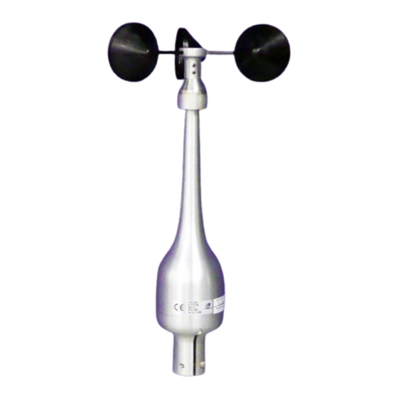
Model 2030 Micro Response Anemometer User's Manual 1. INTRODUCTION The Model 2030 Micro Response Anemometer is a highly responsive three-cup anemometer that uses a photon-coupled chopper to produce an output pulse with a frequency proportional to wind speed. • The threshold of the anemometer is 1 mile per hour. -
Page 6: Installation
2.1 ASSEMBLY With the exception of installing the cup assembly, the Model 2030 Micro Response Anemometer is ready for mounting. Install the cup assembly as described in the steps below. Loosen the two set screws with a 1/16" Allen wrench, and slide the cup assembly over the anemometer shaft. -
Page 7: Mounting
Crossarm without any additional accessories. The crossarm is generally used to mount one each Model 2030 Anemometer and a Model 2020 Vane to form a wind speed and direction measurement set. If the Model 2030 Anemometer is to be mounted separately, a Model 20231 Mast Adapter should be ordered as an accessory. -
Page 8: Wiring
Model 2030 Micro Response Anemometer User's Manual 2.5 WIRING Figure 1 shows the sensor wiring when connecting to the Model 1190 DCP, as used in AWOS systems. Cable number 20306 can be ordered from All Weather, Inc. for direct connection. The cable comes with a mating connector at the sensor end and bare wires for connection at the DCP's terminal block TB2. -
Page 9: Theory Of Operation
Model 2030 Micro Response Anemometer User's Manual 3. THEORY OF OPERATION A light emitting diode in combination with a light sensitive transistor is mounted directly to the anemometer connector. A slotted wheel connected to the anemometer shaft rotates with the shaft and interrupts the light beam between the light emitting diode and the phototransistor. -
Page 10: Calibration
Calibration data in Table 2 were compiled from tests in which the anemometer was operated in a wind tunnel equipped with NIST-traceable measuring instruments. Table 2. Model 2030 Anemometer Calibration Table Frequency Shaft Speed Wind Speed Wind Speed... - Page 11 Model 2030 Micro Response Anemometer User's Manual Table 3. Wind Speed Conversion Factors miles per hour knots meters per second feet per second mph x 0.868 = knots knots x 1.152 = mph m/s x 2.237 = mph ft/s x 0.682 = mph mph x 0.447 = m/s...
-
Page 12: Maintenance
The bearings can be replaced in the field or the anemometer can be returned to All Weather Inc. for servicing. To inspect the bearings, turn the anemometer cup assembly to check that it turns freely and smoothly. -
Page 13: Maintenance Kit
A maintenance kit (P/N M488141) is available for the Model 2030 that provides the parts necessary for basic upkeep of the instrument. The kit includes those parts that are the most susceptible to wear, such as bearings and set screws. To order this kit, contact All Weather Inc. and specify Part Number M488141. -
Page 14: Annual Maintenance
Model 2030 Micro Response Anemometer User's Manual 5.5.4 Annual Maintenance During annual maintenance, perform the following procedures in addition to those outlined for monthly and quarterly maintenance. 1. Set the DCP's LCD display to display wind speed, and verify that the displayed wind speed is reasonable. -
Page 15: Specifications
Model 2030 Micro Response Anemometer User's Manual 6. SPECIFICATIONS Parameter Specification Sensor Type 3-cup assembly, carbon graphite composite, 2" diameter cups Transducer Light Chopper Light Source Excitation 12 V DC, 25 mA 30 pulses/rev, Output 900 Hz @ 88.8 mph Range 0–75 m/s (0–168 mph, 0–156 kt) -
Page 16: Warranty
User's Manual 7. WARRANTY Unless specified otherwise, All Weather Inc. (the Company) warrants its products to be free from defects in material and workmanship under normal use and service for one year from date of shipment, subject to the following conditions: a. -
Page 17: Drawings
Model 2030 Micro Response Anemometer User's Manual 8. DRAWINGS The following pages include reference drawings to assist in installation and maintenance of this instrument. - Page 21 All Weather Inc. 1065 National Drive, Suite 1 Sacramento, CA 95834 2030-001 Fax: 916.928.1165 Revision B Phone: 916.928.1000 April, 2021 Toll Free: 800.824.5873...
Need help?
Do you have a question about the 2030 and is the answer not in the manual?
Questions and answers