
Related Manuals for All Weather Inc 8339

Summary of Contents for All Weather Inc 8339
- Page 1 Model 8339 Cloud Height Indicator Laser Ceilometer User’s Manual Rev. M All Weather Inc. • 1065 National Drive • Sacramento, CA 95834 • USA • 800.824.5873 • www.allweatherinc.com...
- Page 2 Copyright © 2013–2021, All Weather, Inc. All Rights Reserved. The information contained herein is proprietary and is provided solely for the purpose of allowing customers to operate and/or service All Weather, Inc. manufactured equipment and is not to be released, reproduced, or used for any other purpose without written permission of All Weather, Inc.
- Page 3 Enhanced description of grounding requirements during installation. Added cross-reference to status codes in Section 2.3.2 and simplified lens cleaning to 2014 Nov 20 clean water 2016 May 26 Updated 8339-F-019/8339-G-019 wiring diagrams to add wire colors 2021 Feb 5 Added RS-485 surge suppression...
-
Page 4: Table Of Contents
3.3.1 Communication Parameters ....................16 3.3.2 Data Format ........................16 3.4 8339 ASOS ICD ........................17 3.4.1 Communication Parameters ....................17 3.4.2 8339 ASOS ICD Command Set ..................17 4. UNPACKING AND INSTALLATION .................. 27 4.1 Unpacking ..........................27 4.2 Installation ..........................27 4.2.1 Mechanical Mounting ....................... - Page 5 Model 8339 Ceilometer User’s Manual 6.1.2 Blower Check — Monthly ....................35 6.1.3 Desiccant Replacement — Triannually ................35 6.1.4 Blower Housing Cleaning — Annually ................36 6.2 Fuse Replacement ........................36 7. TROUBLESHOOTING ...................... 37 7.1 Using the Status Message ......................37 8.
- Page 6 Failure to do so may damage the system. If fuses blow repeatedly, a serious condition is indicated. Equatorial An equatorial filter that prevents damage to the laser from exposure to direct sunlight is installed on every 8339 Ceilometer. This filter causes no Filter degradation in performance.
-
Page 7: Overview
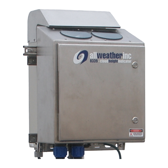
The 8339 is enclosed in a NEMA 4X electro-polished 304 stainless steel package that will stand up to the harshest environmental conditions from corrosive marine air to blowing desert sand. The 8339 is designed to last. -
Page 8: Accessories
Model 8339 Ceilometer User’s Manual 1.2 ACCESSORIES The following accessories are available for the Model 8339 Ceilometer. Part Number Description 83395-00 Battery Backup Kit 83396-00 100–120 V AC Heater/Blower for use with 8339-F 83397-00 200–240 V AC Heater/Blower for use with 8339-G... -
Page 9: Theory Of Operation
In other words, that distance where 95% of the initial laser beam has been extinguished by scattering. The 8339 works in accordance with the principal of optical radar, or LIDAR. A laser pulse is emitted at a maximum rate of 1 kHz vertically into the atmosphere, and the resulting backscattering is analyzed for water density. -
Page 10: Functional Description
Some clouds are much more difficult to detect than others, due, for example, to poorly defined borders or a sparse composition. The proprietary algorithms used in the 8339 are adaptive to these conditions, allowing the Ceilometer to provide accurate information even in difficult circumstances. -
Page 11: Modules
User’s Manual 2.3 MODULES The Model 8339 Ceilometer is made up of the following major modules. The Optical Module (M403434-01) contains the laser, the receiver, and the dirty window detector electronics, as well as the condenser lenses, interference filter, and high voltage switching regulators. - Page 12 Model 8339 Ceilometer User’s Manual The optical module consists of two 4" aspherical condenser lenses mounted atop a brazed aluminum cylinder frame. The module attaches to the base of the Ceilometer with four connectors that are easily removed in the field.
- Page 13 Model 8339 Ceilometer User’s Manual Externally Visible Ceilometer Status LEDs A small circuit board is mounted inside the top of the Ceilometer enclosure, and is visible from outside the unit through the transmitter window. Three LEDs on this board indicate Ceilometer status.
-
Page 14: Data Acquisition Board
Table 2. System Operating Parameters Parameter Possible Settings Default Setting Output Interval 30, 60, 120 sec. 30 sec. All Weather, Inc. 8339 format; All Weather, Inc. 8339 format; Data Format 25,000', auto output 25,000', auto output Control Local, remote Local... - Page 15 Model 8339 Ceilometer User’s Manual A row of red LEDs along the edge of the board indicates the status of the Ceilometer. Their functions are shown in Table 3. A status message outputs more detailed status codes (Table 23) for troubleshooting.
-
Page 16: Fault Detection
30 second reporting 60 second reporting 120 second reporting 8339 Native Format 8329 Format 8339 ASOS Format 8339 Sky Condition Format 300 Baud 1200 Baud 4800 Baud 9600 Baud 2.4 FAULT DETECTION When a fault is detected during the Ceilometer’s self-testing, a fault message is output over the communication line. -
Page 17: Data Communication
Handshaking None 3.1.2 Data Format The 8339 Native Data format is output from the Ceilometer in a data string consisting of eight fields. Table 6. 8339 Native Data Output Data Format Output Data String TR1 AAAAAA HHHHH TTTT HHHHH TTTT HHHHH TTTT HHHHH TTTT VVVV RRRRR... -
Page 18: Poll Commands
Cloud height in feet TTTT Penetration depth in feet VVVV Vertical visibility RRRRR Range setting in feet CCCC CRC 16 CHIIDN? <ADDR><CR><LF> – Identification Poll Command Output Data String AWI 8339/8340 Ceilometer X.YY CCCC Character Sequence Meaning X.YY Ceilometer version CCCC CRC 16... - Page 19 Model 8339 Ceilometer User’s Manual CHICONFIG<ADDR><CR><LF> – Configuration Request Poll Command Returns the active configuration that is stored in flash followed by a CRC 16 Return String 000799a58f00003000ef0bb862620308275d11090080205740015a5ae60100ffffff CCCC Character Sequence Meaning Sample string Active configuration stored in flash memory...
-
Page 20: 8339 Sky Condition Format
User’s Manual 3.2 8339 SKY CONDITION FORMAT The 8339 Sky Condition Format provides real-time reports of cloud bases and depths as well as the Sky Condition based on the NWS ASOS Sky Condition algorithm. The Sky Condition algorithm uses a weighted average of 30-second cloud hit reports over a 10-minute period to determine the cloud cover. -
Page 21: Data Format
Model 8339 Ceilometer User’s Manual 3.2.1 Data Format The 8339 Sky Condition Format is output from the Ceilometer in a data string consisting of seven fields. Table 8. 8339 Sky Condition Output Data Format Output Data String TR1 AAAAAA HHHHH TTTT HHHHH TTTT HHHHH TTTT HHHHH TTTT VVVV RRRRR ,SKYCOND... -
Page 22: 8329 Format
The Model 8339 Ceilometer may replace an Model 8329 Ceilometer in an existing AWOS. The 8329 Format enables the Model 8339 Ceilometer to continue report data using the 8329 format used by the Model 8329 Ceilometer without making changes to the AWOS. -
Page 23: 8339 Asos Icd
The 8339 ASOS ICD meets the requirements of NWS-S100-CHI-SP1000 Sections 3.3.5 and 3.3.6. NWS-S100-CHI-SP1000 calls out the commands and the response format to be used when Ceilometers are part of an ASOS system. The 8339 implements these commands as detailed in this section. - Page 24 User’s Manual 8339 ASOS CA Command The 8339 ASOS CA command supports the ASOS regular polling for sensor data. The sensor data contains sensor status, cloud height information or hits, and monitoring data. Table 13. Responses to ASOS CA Command...
- Page 25 User’s Manual 8339 ASOS CD Command The 8339 ASOS CD command supports operator access to the extended diagnostic capabilities of the Model 8339 Ceilometer. The operator executes the command through the RS-232 or RS-485 port. The results of the diagnostic tests are presented using descriptive text and/or raw sensor values were appropriate.
- Page 26 Model 8339 Ceilometer User’s Manual Position Description Value 52–53 Optical Module Temperature XX (corresponding to hex count) Voltage 55–56 Checksum CC (Note 2) End of Text Carriage Return Line Feed Note 1: "P" (Pass) indicates all diagnostic tests have passed and the sensor is functioning normally.
- Page 27 User’s Manual 8339 ASOS CF Command The 8339 ASOS CF command returns a fixed output corresponding to the CA output and used to validate sensor operation and communication wiring. The status will always report failed and the cloud heights will be 97654.
- Page 28 8339 ASOS CH Command The 8339 ASOS CH command displays a list of all available commands, the syntax, and description. As the display is intended to be used by an operator connected via the RS-232 or RS-485 port to a laptop computer, a simple scrolling output is used.
- Page 29 User’s Manual 8339 ASOS CL Command The 8339 ASOS CL command enables automated control of heaters for keeping freezing and solid precipitation from blocking critical sensing elements. The sensor, after processing the command, will use internal algorithms to control the heater operation. The result of the command indicates the status of the heater at completion.
- Page 30 User’s Manual 8339 ASOS CM Command The 8339 ASOS CM disables automated control of heaters for keeping freezing and solid precipita- tion from blocking critical sensing elements. The sensor, after processing the command, will energize the heaters. To disable manual override of energizing the heater, a CL, CN or CR command must be sent to the Ceilometer.
- Page 31 User’s Manual 8339 ASOS CN Command The 8339 ASOS CN command disables automated control of heaters for keeping freezing and solid precipitation from blocking critical sensing elements. The sensor, after processing the command, will disable the heaters. Manual override of disabling the heaters can only be accomplished via a CL, CM or CR command.
- Page 32 User’s Manual 8339 ASOS CS Command The 8339 ASOS CS command supports operator access to diagnostic tests. The operator executes the command through the RS-232 or RS-485 port via an external laptop computer. The results of the diagnostic tests shall be presented in descriptive text using a simple scrolling format.
-
Page 33: Unpacking And Installation
+70°C during shipment and storage. 4.2 INSTALLATION The 8339 must be firmly mounted to a vertical 2½" pipe for proper operation. Any movement of the 8339 due to wind or other causes will reduce the accuracy of the Ceilometer. The Ceilometer should be installed in an open area away from trees, buildings, or other obstructions. -
Page 34: Mechanical Mounting
Model 8339 Ceilometer User’s Manual 4.2.1 Mechanical Mounting Ceilometer The Ceilometer mounts on the mast using the M488261-00 Mounting Kit. Refer to drawing M488261-00-007 at the back of this manual and to Figure 6 during installation. Mount the Ceilometer on the mast with the top of the enclosure 5'6" (167 cm) from ground level, or at least 3 ft (1 meter) above the maximum snow level using Mounting Kit M488261-00. -
Page 35: Optional Heater/Blower
Model 8339 Ceilometer User’s Manual 4.2.2 Optional Heater/Blower The optional Heater/Blower mounts on the mast using the supplied Unistrut and clamps. 1. Mount the Heater/Blower on the mast as shown in installa- tion drawing 83396-00-007 (100–120 V) or 83397-00-007 (200–240 V) at the back of this manual. -
Page 36: Ceilometer Lightning Surge Suppressor
Model 8339 Ceilometer User’s Manual 4.2.3 Ceilometer Lightning Surge Suppressor 1. Remove the cover from the Lightning Surge Suppressor. 2. Strip off about ¼" of insulation from one end of the ground wire included with the Lightning Surge Suppressor and route the green ground wire with an orange stripe through the gland to one of the ground terminal blocks as shown in Figure 8. -
Page 37: Ceilometer Data Connection
Model 8339 Ceilometer User’s Manual 4.2.4 Ceilometer Data Connection 1. Connect the M491894-00 cable from the Lightning Surge Suppressor (Figure 8) to the CEILOMETER DATA connector on the underside of the Ceilometer (see Figure 10). Figure 10. Ceilometer Connectors 2. Connect the data cable’s circular connector to the M491893-00 cable connector from the Lightning Surge Suppressor (Figure 8). -
Page 38: Ceilometer Power Connection
Ensure that the circuit breaker for the Ceilometer in the main power distribution box is in the OFF position. 1. Set the main circuit breaker in the 8339 to the OFF position (see Figure 1). 2. Connect the power cord’s circular connector to the INPUT POWER connector on the underside of the Ceilometer (see Figure 10). - Page 39 Model 8339 Ceilometer User’s Manual 4.2.6.1 Desiccant 1. The desiccant package (M028179-00) is secured inside the Ceilometer by tie-wraps. To preserve the desiccant material, the package is sealed within a plastic bag during shipment. Remove and discard the plastic bag, then replace the desiccant package in its tie-wrap holder (see Figure 10).
-
Page 40: Operation
Model 8339 Ceilometer User’s Manual 5. OPERATION 5.1 POWER UP 1. Before closing the Ceilometer door, make sure the circuit breaker switch is in the "ON" (up) position (Figure 9). 2. Apply prime power. 5.2 CHECKOUT After powering on the Ceilometer, check the status LEDs (see Figure 4) to verify proper operation. -
Page 41: Maintenance
Model 8339 Ceilometer User’s Manual 6. MAINTENANCE 6.1 PERIODIC MAINTENANCE 6.1.1 Window Cleaning — Monthly or as required Clean the transceiver windows at least once per month (more frequently if local conditions warrant), or when the status message so indicates. Note that a dirty window warning message may also appear during rain, snow, and fog conditions - whenever the internal electronics measure a certain amount of window obfuscation. -
Page 42: Blower Housing Cleaning - Annually
Model 8339 Ceilometer User’s Manual within a plastic bag during shipment. Remove and discard the plastic bag, then replace the desiccant package in its tie-wrap holder (see Figure 10). 6.1.4 Blower Housing Cleaning — Annually During annual maintenance, clean the blower housing as follows: Remove the six Phillips screws from the blower housing’s rear panel, and remove the rear... -
Page 43: Troubleshooting
Model 8339 Ceilometer User’s Manual 7. TROUBLESHOOTING 7.1 USING THE STATUS MESSAGE The first step in troubleshooting Ceilometer problems is consulting the output message’s status message. This is a six-character hexadecimal code that follows immediately after the TR1 identifier in the data string (see Data Format on page 13). - Page 44 Model 8339 Ceilometer User’s Manual One part of the self-test routine is the dirty window detector. Dirty window outputs must be evaluated with an awareness of current weather conditions, since precipitation will often trigger a dirty window alert. Unit does not operate at all; no Status LED 1.
- Page 45 Model 8339 Ceilometer User’s Manual 2. Check connections between modules (see Figure 16, Figure 17, Figure 18, and Figure 19). Remove connectors and reconnect them, then turn the system on again. 3. If both the optical module and Data Acquisition Board indicate failures, disconnect the optical module’s three cables from the Data Acquisition Board to ensure it is not causing the Data...
-
Page 46: Removal And Replacement
Model 8339 Ceilometer User’s Manual 8. REMOVAL AND REPLACEMENT 8.1 REMOVING MODULES IMPORTANT Observe ESD grounding procedures when handling modules. Do not change modules during weather events; never allow precipitation to enter the interior of the Ceilometer. Whenever a module is being changed, the prime power should be shut off remotely. The only time the remote power switch should be on with the Ceilometer door open is when checking system operation during troubleshooting. -
Page 47: Data Acquisition Board
Model 8339 Ceilometer User’s Manual 8.1.1 Data Acquisition Board Figure 17. Data Acquisition Board Removal 1. The Data Acquisition Board is mounted to the Ceilometer door. 2. Disconnect eight cables from the Data Acquisition Board. 3. Remove the six screws at the corners and sides of the board. -
Page 48: Optical Module
Model 8339 Ceilometer User’s Manual 8.1.2 Optical Module Figure 18. Optical Module Removal 1. Disconnect the ribbon cable and coaxial cable from the Data Acquisition Board. 2. Disconnect the heater cable and power supply cable from the Optical Module. 3. Remove the two screws securing the Optical Module to the enclosure. -
Page 49: Din Rail Components
Model 8339 Ceilometer User’s Manual 8.1.3 DIN Rail Components The Power Supply and Circuit Breaker are installed on a DIN rail beneath the optical module. Figure 19. DIN Rail Component Removal Follow the steps below to remove either component. Power Supply 1. -
Page 50: Replacing Modules
Model 8339 Ceilometer User’s Manual Circuit Breaker 1. Use a screwdriver to disconnect the four wires (two on the top and two on the bottom) from the Circuit Breaker. 2. Using a screwdriver, depress the tab at the bottom of the Circuit Breaker. -
Page 51: Din Rail Components
Model 8339 Ceilometer User’s Manual 8.2.3 DIN Rail Components The Power Supply and Circuit Breaker are installed on a DIN rail beneath the optical module. Follow the steps below to replace either component. 1. With the bottom of the component angled slightly out, hook the top DIN rail clip onto the DIN rail. -
Page 52: Firmware Updates
Model 8339 Ceilometer User’s Manual 9. FIRMWARE UPDATES The Ceilometer Firmware Update Tool User’s Manual (M595167-00-001) describes the tools and procedures for updating the Model 8339 Ceilometer firmware. -
Page 53: Specifications
Model 8339 Ceilometer User’s Manual 10. SPECIFICATIONS Specification Parameter 8339-F 8339-G to 25,000 ft. or to 12,500 ft Measurement Range (selectable) Resolution 12.5 ft Accuracy ±20 ft. over full range Cloud Layers up to four, base and depth Configurable to 30-, 60-, or 120-second sampling/ Measurement Cycle reporting interval;... - Page 54 Model 8339 Ceilometer User’s Manual Specification Parameter 8339-F 8339-G Mechanical Mounting Unistrut mounted on single- leg pedestal; 2½" pipe Ceilometer NEMA 4X electro-polished 304 stainless steel Enclosure Optional Heater/Blower Aluminum 19" H × 16" W × 9" D Dimensions Ceilometer (48 cm ×...
-
Page 55: Warranty
User’s Manual 11. WARRANTY Unless specified otherwise, All Weather Inc. (the Company) warrants its products to be free from defects in material and workmanship under normal use and service for one year from date of shipment, subject to the following conditions:... -
Page 56: Drawings
User’s Manual 12. DRAWINGS The following pages contain drawings to help in the installation, use, and maintenance of this instrument. Schematics 8339-F-019 8339-F Top Level Wiring Diagram 8339-G-019 8339-G Top Level Wiring Diagram M403437-04-019 Heater/Blower Wiring Diagram (100–120 V AC) M403438-04-019 Heater/Blower Wiring Diagram (200–240 V AC) - Page 57 allweatherinc...
- Page 58 allweatherinc...
- Page 66 Model 8339 Ceilometer Site Preparation...
- Page 67 CEILOMETER 25K + BLOWER (100-120VAC) CEILOMETER 25K + BLOWER (200-240VAC) CEILOMETER 40K + BLOWER (100-120VAC) CEILOMETER 40K + BLOWER (200-240VAC) Model Numbers 8339-F + 83396, 8339-G + 83397 8340-F + 83396, 8340-G + 83397 Test Report Number ALL-0502-4469-SAFETY Date of Testing...
- Page 68 CEILOMETER 25K + BLOWER (100-120VAC) CEILOMETER 25K + BLOWER (200-240VAC) CEILOMETER 40K + BLOWER (100-120VAC) CEILOMETER 40K + BLOWER (200-240VAC) Model Numbers 8339-F + 83396, 8339-G + 83397, 8340-F + 83396, 8340-G + 83397 Test Report Number ALL-0502-4468-CE Date of Testing 2005, September 20...
- Page 69 All Weather Inc. 1065 National Drive, Suite 1 Sacramento, CA 95818 8339-F-001 Fax: 916.928.1165 Revision M Phone: 916.928.1000 February, 2021 Toll Free: 800.824.5873...
Need help?
Do you have a question about the 8339 and is the answer not in the manual?
Questions and answers