Table of Contents
Advertisement
Sales Partner:
absolute-emc.com
Phone:703-774-7505
info@absolute-emc.com
Industrial Power Corruptor
User's Manual
IPC-480V-200A
IPC-480V-100A
IPC-480V-50A
IPC-240V-25A
Manual Revision 1.00
page 1
Industrial Power Corruptor Manual Rev 1.00
Power Standards Lab
1201 Marina Village Parkway #101
Alameda, California 94501 U.S.A.
TEL ++1-510-522-4400
FAX ++1-510-522-4455
www.PowerStandards.com
R
PSL
PSL
PSL
PSL
PSL
Advertisement
Table of Contents

Related Manuals for PSL IPC-480V-200A

Summary of Contents for PSL IPC-480V-200A
- Page 1 Industrial Power Corruptor Manual Rev 1.00 Power Standards Lab 1201 Marina Village Parkway #101 Alameda, California 94501 U.S.A. TEL ++1-510-522-4400 FAX ++1-510-522-4455 www.PowerStandards.com Industrial Power Corruptor User’s Manual IPC-480V-200A IPC-480V-100A IPC-480V-50A IPC-240V-25A Manual Revision 1.00 Sales Partner: absolute-emc.com Phone:703-774-7505 info@absolute-emc.com...
- Page 2 LIMITED TO, THE IMPLIED WARRANTIES OF MERCHANTABILITY AND FITNESS FOR A PARTICULAR USE. PSL shall not be liable for errors contained herein or for incidental or consequential damages in connection with the furnishing, performance, or use of this material. Printed in the United States of America.
- Page 3 Industrial Power Corruptor Manual Rev 1.00 SYMBOL TABLE Symbol Meaning Caution. Refer to this manual. Caution. Risk of electric shock. Fuse. Replace only with indicated rating and type. Alternating current Protective conductor terminal (earth) Heavy. Risk of injury. Do not attempt to lift by yourself.
-
Page 4: Table Of Contents
Table of Contents Industrial Power Corruptor Manual Rev 1.00 1. Overview ..................................6 1.1 What is an Industrial Power Corruptor? ......................... 6 1.2 What is a voltage sag? ............................6 1.3 What is a voltage swell? ............................7 1.4 Why generate sags and swells? ..........................7 1.5 Why use a multi-channel data acquisition system? .................... - Page 5 Industrial Power Corruptor Manual Rev 1.00 3.3.5 RJ-45 rear panel communications ports ..................... 30 3.3.6 Analog outputs ............................. 30 3.3.7 Motor drive for circuit breaker (optional) ..................... 31 3.3.7 Impulse generator connectors (optional) ..................... 31 3.5 Software ................................32 3.5.1 Brief description ........................... 32 3.5.2 System Requirements ..........................
-
Page 6: Overview
Industrial Power Corruptor Manual Rev 1.00 1. Overview 1.1 What is an Industrial Power Corruptor? An Industrial Power Corruptor produces bad quality electric power, reliably and repeatedly. Power from a clean source, such as your electric company, passes through your IPC. Your IPC then adds disturbances - sags, swells, interruptions, etc. -
Page 7: What Is A Voltage Swell
Industrial Power Corruptor Manual Rev 1.00 1.3 What is a voltage swell? A voltage swell is the opposite of a voltage sag. It is a brief increase in RMS voltage on the AC power circuit. Although the negative impacts of small voltage swells are rare, certain types of equipment are highly susceptible to these fluctuations. -
Page 8: Safety Features Of Your Ipc
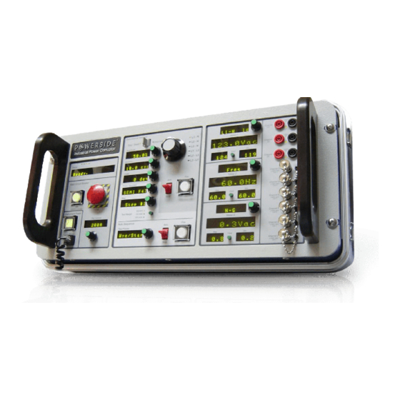
Industrial Power Corruptor Manual Rev 1.00 True (not simulated) phase-to-phase sags and swells can be generated. The front panel of your IPC is packed with an extensive array of control and monitoring functions. The Disturbance Settings section on the front panel lets you set depth, duration, angle, and phase settings for your event. -
Page 9: Testing
Industrial Power Corruptor Manual Rev 1.00 2. Testing 2.1 Testing equipment with your Industrial Power Corruptor Use your Industrial Power Corruptor to test equipment that your have designed or purchased. You can test for immunity to voltage sags or swells, measure start-up current surges, and - with the IPC's Power Flow Analysis option - verify power factor, harmonics, and power consumption. - Page 10 Industrial Power Corruptor Manual Rev 1.00 It is a very good idea to prepare a written check-list. Use it every time you begin a new test. Prior to connecting your IPC: Verify exit locations. Locate the nearest fire extinguisher. Find the nearest telephone, and identify the emergency telephone number.
-
Page 11: Unpacking Your Industrial Power Corruptor
Industrial Power Corruptor Manual Rev 1.00 2.2.3 Unpacking your Industrial Power Corruptor Your IPC is a sensitive and calibrated piece of electronic test equipment. It is also heavy, which can lead to damage if not handled with extreme care. Your IPC is shipped to you in a custom wooden crate with supportive packing. -
Page 12: Connecting Test Power
Industrial Power Corruptor Manual Rev 1.00 2.2.6 Connecting test power You will insert your IPC between your main source of power and the equipment you plan to test. On the rear of your IPC, find the 10 large gray terminal blocks, five labelled “from SOURCE”... -
Page 13: Single-Phase Power Connections
Industrial Power Corruptor Manual Rev 1.00 2.2.6.1 Single-phase power connections Warning: Death, serious injury, or fire hazard could result from improper connection of this instrument. The rear of the IPC is a high voltage, high current area. Follow industry standard safety precautions at all times. Do not make electric power connections unless you are qualified to do so. - Page 14 Industrial Power Corruptor Manual Rev 1.00 terminal block. Failure to use a wire adaptor will result in poor clamping to the conductor and dangerous access to high voltage wires/surfaces. As a standard practice, mount wire adaptors in any terminal blocks that do not have conductors inserted. This will prevent finger access to un-used terminal block contacts.
-
Page 15: Three-Phase Delta Power Connections
Industrial Power Corruptor Manual Rev 1.00 2.2.6.2 Three-phase delta power connections Warning: Death, serious injury, or fire hazard could result from improper connection of this instrument. The rear of the IPC is a high voltage, high current area. Follow industry standard safety precautions at all times. Do not make electric power connections unless you are qualified to do so. - Page 16 Industrial Power Corruptor Manual Rev 1.00 terminal blocks that do not have conductors inserted. This will prevent finger access to potentially high voltage terminal block contacts. The sag/swell events will be generated from phase-to-phase. If you want phase-to-neutral events, connect your IPC for wye installation (see next page).
-
Page 17: Three-Phase Wye (Star) Power Connections
Industrial Power Corruptor Manual Rev 1.00 2.2.6.2 Three-Phase wye (star) power connections Warning: Death, serious injury, or fire hazard could result from improper connection of this instrument. The rear of the IPC is a high voltage, high current area. Follow industry standard safety precautions at all times. Do not make electric power connections unless you are qualified to do so. - Page 18 Industrial Power Corruptor Manual Rev 1.00 If larger conductors are connected directly into the terminal blocks, O-rings or similar protective insulating devices should be used to ensure that it is impossible to touch bare conductors or terminal block contacts. The sag/swell events will be generated from phase-to-phase and phase to neutral.
-
Page 19: Types Of Testing
Industrial Power Corruptor Manual Rev 1.00 2.3 Types of testing 2.3.1 Choosing the type of test Your IPC can perform several different types of electric power tests: voltage sag and swell immunity, power supply sustain time after interruptions, unbalance response, inrush current, and power consumption / harmonics tests. -
Page 20: Power Consumption And Harmonic Testing
Industrial Power Corruptor Manual Rev 1.00 Your IPC can also control the phase angle where power is re-applied. On three-phase systems, this phase angle can be specified for any voltage conductor pair. You can specify the duration of the interruption. It should be long enough to allow the EUT's capacitors to discharge, motors to slow down, etc. -
Page 21: Technical Description Of Your Industrial Power Corruptor
Industrial Power Corruptor Manual Rev 1.00 3. Technical Description of your Industrial Power Corruptor 3.1 General description 3.1.1 Theory of Operation Your IPC is a transformer-based disturbance generator. It contains an autotransformer with multiple taps, and an extensive series of switches (electromechanical and Insulated Gate Bipolar Transistors). -
Page 22: Major Modules
Industrial Power Corruptor Manual Rev 1.00 3.1.2 Major modules Your IPC has been designed in a modular format to assist in manufacturing, quality control, and service. These primary modules are as follows: Front Panel Assembly Consists of a Display printed circuit board (PCB) and a Control PCB mounted to the front panel with labels. - Page 23 Industrial Power Corruptor Manual Rev 1.00 Transformer Assembly The custom designed multi-tapped autotransformer is used to select the depth of a sag or swell. This transformer is mounted on its own support plate that also has an insulating termination plate. The terminations from the transformer connect to this plate and in turn receive a fuse link connection to the Tap Relay Assembly.
-
Page 24: Front Panel Features
Industrial Power Corruptor Manual Rev 1.00 3.2 Front panel features The front panel of your IPC is the primary functional interface. It has been design to be as user friendly as possible, while allowing maximum functionality and information display. It is separated into 3 main sections: "... -
Page 25: Sag / Swell - Impulse Switch
Industrial Power Corruptor Manual Rev 1.00 Source: terminal block connections from the "to Load" terminal block connections. If the optional Motor Operator assembly is installed, the covered Circuit Breaker "ON" button on the front panel will function as a switch to close the circuit breaker. When this is depressed, you will hear the motor operator close the circuit breaker, and the light on the switch will turn from red to green. -
Page 26: Step Dial / Display
Industrial Power Corruptor Manual Rev 1.00 3.2.9 Step dial / display When you select a multiple-step standard recipe on the Power Standard display, this dial permits you to choose which of the steps you want to perform. This allows you to step through a multi-step test, or go back to earlier steps if desired. -
Page 27: Test Phases Dial / Display
Industrial Power Corruptor Manual Rev 1.00 3.2.13 Test Phases dial / display This is part of the Auto Sequence function. Auto sequence automatically advances you to the next step and/or phase on a multi-step test. For safety reasons, you still have to "arm" and "fire"... -
Page 28: High Voltage Input Channels
Industrial Power Corruptor Manual Rev 1.00 3.2.16 High Voltage Input Channels The pairs of banana jack connectors on the right hand side of the front panel, labeled Channel 21, Channel 22, and Channel 23 are ±600V AC or DC analog inputs. You can use these to monitor high voltage points on the equipment you are testing. -
Page 29: Rear Panel Connections
Industrial Power Corruptor Manual Rev 1.00 3.3 Rear panel connections 3.3.1 Instrument power Find the AC inlet on the lower left of the rear panel. Connect instrument power here; see specifications for acceptable voltages and frequencies. The instrument power supply automatically adjusts to the voltage and frequency. -
Page 30: Triggers In/Out Bnc Connectors (Panic, Arm, And Sag)
Industrial Power Corruptor Manual Rev 1.00 3.3.4 Triggers in/out BNC connectors (panic, arm, and sag) On the upper left corner of the rear panel there are three BNC connectors. These are 0V min, 24V max signals. Do not connect other voltages to these connectors. -
Page 31: Motor Drive For Circuit Breaker (Optional)
Industrial Power Corruptor Manual Rev 1.00 3.3.7 Motor drive for circuit breaker (optional) This convenient option lets you close the circuit breaker from the front of the IPC, avoiding the requirement to reach over to the back of the IPC (near high voltage connections) in order to manually turn the breaker on. -
Page 32: Software
The Power Flow Analysis option adds vector scopes, power waveforms, so PSL provides two additional programs. spectrum analyzers, harmonics meters, and every imaginable kind of power flow meter - kWh, power The ChannelScope is a program that lets you graph factor, kVAR, THD, and much more. - Page 33 IPC software will give you a warning message. The optional Power Flow Analysis software requires more processing power than the rest of the programs. PSL can provide a free software tool for checking your serial ports. Contact us at www.PowerStandards.com . absolute-emc.com Phone:703-774-7505 info@absolute-emc.com...
-
Page 34: Installation
Industrial Power Corruptor Manual Rev 1.00 3.5.3 Installation Insert your IPC CD-ROM. It should automatically start. (If it does not start, browse your CD-ROM and double-click on the "CDStart" application.) Click on the "Install IPC Software" link. You will probably be asked if you want to download the program, or run it or open it in its existing location. -
Page 35: Planning Your Test
You can use the "COM Port Diagnostics" program from PSL to check your com ports. Properly connected to your IPC, the software is ready to help you set up your testing session. -
Page 36: Setting Up Your Testing Session
Industrial Power Corruptor Manual Rev 1.00 3.5.4.3 Setting up your testing session Use the "Setup" pull-down menu to record all the information about your testing session. You can record information about the "Equipment Under Test", the engineers who are involved in the testing, the nominal voltages and frequencies, and more. -
Page 37: On-Screen Meter
Industrial Power Corruptor Manual Rev 1.00 3.5.5 On-screen meter Click on the "Launch meter" button. You can choose an analog or a digital meter, and you can connect it to any of your IPC's data acquisition channels. For more information about how these channels function, see the "Meters"... -
Page 38: Triggering, Selecting Channels, And Downloading
Industrial Power Corruptor Manual Rev 1.00 3.5.6 Triggering, selecting channels, and downloading Your IPC contains a 35-channel digital oscilloscope, capable of recording several seconds of high-speed data on every channel. This oscilloscope is automatically triggered whenever you use your IPC to generate a disturbance event, but you can also manually trigger it with the "Manual trigger"... - Page 39 Industrial Power Corruptor Manual Rev 1.00 which channels to download, and to re-name the channels. It is helpful to keep the channel names to 5 characters or less, for example "+24V". These new names will appear on your IPC's front panel meters, the on- screen meter, and on the ChannelScope waveforms, making it much easier to keep track of what each channel is used for.
-
Page 40: Power Flow Analysis Option
Industrial Power Corruptor Manual Rev 1.00 3.5.7 Power flow analysis option By default, your IPC operates as a disturbance generator. But by clicking the "Power Flow Analyzer" button on the opening screen, your IPC can become a sophisticated, easy-to-use power meter. -
Page 41: Power Flow Meters
Industrial Power Corruptor Manual Rev 1.00 3.5.7.1 Power flow meters The power flow meters show the present value, as well as the minimum and maximum value, for each parameter. Click on the small button between the min/max meters to reset the min/max values. All of the meters are calculated from phase-locked, 128-sample- per-cycle data. - Page 42 Industrial Power Corruptor Manual Rev 1.00 can reset this meter to zero, at any time, by pressing its "Clear" button. Useful for measuring the energy consumption of your industrial process. Amps (RMS) - The true RMS current on the phase conductor with the largest current.
-
Page 43: Oscilloscope / Spectrum Analyzer
Industrial Power Corruptor Manual Rev 1.00 3.5.7.2 Oscilloscope / spectrum analyzer Analyzing power system waveforms is easy. Just click the "Oscilloscope / Spectrum analyzer" button on the Power Flow Analysis screen. Use the box at the upper right to choose the channel, and to set the full-scale reading for both the oscilloscope and the spectrum analyzer. - Page 44 Industrial Power Corruptor Manual Rev 1.00 To see individual harmonics, click on the "Harmonics meters" button. The "copy" button places the present value in all of the harmonic meters onto your computer's clipboard, formatted as simple text. absolute-emc.com Phone:703-774-7505 info@absolute-emc.com page 44...
-
Page 45: Vector Scope
Industrial Power Corruptor Manual Rev 1.00 3.5.7.4 Vector scope Your IPC's Power Flow Analysis option includes a sophisticated, real-time vector scope. You can use this tool to verify phase rotation, and to check the angles and balance of voltages and currents. The VectorScope extracts and analyzes the fundamental voltages and currents, and their relative angles;... -
Page 46: Power Flow Recorder
Industrial Power Corruptor Manual Rev 1.00 3.5.7.5 Power flow recorder The Power Flow Recorder is probably the most powerful and useful feature of your IPC's Power Flow Analysis option. You can record all of the power flow parameters, in real time, to your computer's disk. -
Page 47: Channelscope Ii
Industrial Power Corruptor Manual Rev 1.00 3.5.8 ChannelScope II The ChannelScope II software lets you work with recorded power waveforms. You can graph them, zoom in and out, synchronize across channels, pick out values on waveforms, convert complex waveforms to RMS values, and more. - Page 48 Industrial Power Corruptor Manual Rev 1.00 Start the ChannelScope II software, then use the File menu to open the sample data file. Under the Options menu, select "Event Details". You will see the date and time the event was recorded, all of the information about the test equipment and the Equipment Under Test, and - if you entered the optional information during the download - comments about what happened during the test.
- Page 49 Industrial Power Corruptor Manual Rev 1.00 cursor in a graph, hold the left mouse button down, and slide the cursor left or right. Then align all of the graphs by clicking on the yellow cursor button. To restore the default left-right values, click on the button with the exclamation mark.
-
Page 50: Flowscope
Industrial Power Corruptor Manual Rev 1.00 3.5.9 FlowScope The FlowScope software lets you analyze and graph power flow parameters. It is optimized for analyzing industrial processes. Use your IPC's Power Flow Recorder (part of the Power Flow Analysis option) to record a data file for the FlowScope software. Two sample data files are provided with the program. -
Page 51: Appendix A - Status Messages
Industrial Power Corruptor Manual Rev 1.00 Appendix A - Status messages Armed. The IPC is armed and ready to perform the next event. Press one of the “Fire” buttons to trigger the event. Bad snubber fuse The user has attempted to start and event, but the IPC has detected that one or more of the fuses on the IGBT snubber board is open. - Page 52 Industrial Power Corruptor Manual Rev 1.00 Ready. (no AC) The IPC is ready to perform an event, but it cannot find any zero-crossings on the channel selected by the Phase Selector knob. Apply power to the IPC, or choose the correct phase. Starting up…...
- Page 53 Industrial Power Corruptor Manual Rev 1.00 Trip:src L1-L2 V Trip:src L2-L3 V Trip:src L3-L1 V The IPC tripped its main circuit breaker because the voltage between the indicated pair of terminals, on the source side, exceeded 125% of the IPC’s voltage rating. Trip:Stuck0 RLNN The IPC tripped its main circuit breaker because the one of its internal relays, indicated by NN, failed to transition from its “off”...
-
Page 54: Appendix B - Specifications - General
Industrial Power Corruptor Manual Rev 1.00 Appendix B - Specifications - general General specifications Voltage Sag/Dip and Swell testing per SEMI F47, IEC 6100-4-11, CBEMA, ITIC, MIL STD, FAA, SAMSUNG, and other international standards. With Power Flow Analysis Functional option, also performs to SEMI E6, current inrush testing, harmonic current testing, and more. - Page 55 Industrial Power Corruptor Manual Rev 1.00 Data Acquisition Internal Analog Input 13 internal voltage channels, 6 internal current channels, 3 protective earth current Channels monitoring channels. 3 front panel ±600V (AC or DC) channels, 6 front panel ±100V ( AC or DC) channels. External Analog Input Channels Three front panel meters (including min.
-
Page 56: Appendix C - Specifications - Maximum Allowable Current
Industrial Power Corruptor Manual Rev 1.00 Appendix C - Specifications - Maximum allowable current Note 1: During a sag/swell event, there is a 600-amp instantaneous trip point. On IPC’s rated for 200 amps, this trip point can be increased to 700 amps by placing the IPC into Combat Mode. Note 2: The time for this threshold is frequency-dependent. - Page 57 Industrial Power Corruptor Manual Rev 1.00 240V) for a single cycle. Here is a complete list of reasons that the IPC may trip its main circuit breaker: 1. Overcurrent on any source or load phase conductor (see discussion on previous page) 2.
-
Page 58: Appendix D - Theory Of Operation
Industrial Power Corruptor Manual Rev 1.00 Appendix D - Theory of Operation The IPC is inserted between an AC power source and Equipment Under Test (EUT). Power terminals on rear panel: The power terminals are grouped into "source" and "load" terminals. Each set of terminals can accept up to three (3) phase conductors, an optional neutral conductor, and a required protective earth conductor. - Page 59 Industrial Power Corruptor Manual Rev 1.00 the Panic signal, and the main circuit breaker is tripped. On the Power Supply board, the AC supply is fused on both line and neutral, and has MOV surge suppressors. From the Power Supply board, the AC supply then passes through a cable to the Front Panel Board, where the IPC on/off switch is located.
Need help?
Do you have a question about the IPC-480V-200A and is the answer not in the manual?
Questions and answers
Where Can I get spare Parts? We have lost the cable between device and Computer…. The RJ 45 and Sub 9d Connection? Any electrical drawing available that I can make the cable by myself?