
Related Manuals for Pertici Univer 50

Summary of Contents for Pertici Univer 50
- Page 1 Via delle Città, 41/43 50052 Certaldo (FI) - Italy Tel. +39 0571 652365 Fax +39 0571 652991 email: info@pertici.it www.pertici.it...
-
Page 3: Table Of Contents
ENG Rev 1 SINGLE MITRE SAW 50 page 1 CONTENTS 1. GENERAL INFORMATIONS ..........................3 1.1. M ............................3 ANUFACTURER 1.2. I .............................. 3 NTRODUCTION 1.3. S ........................3 TRUCTURE OF THE HANDBOOK 1.3.1. P ........................ 3 URPOSE AND CONTENTS 1.3.2. - Page 4 ENG Rev 1 SINGLE MITRE SAW 50 page 2 6.2. E ) ..................... 51 XTRAORDINARY MAINTENANCE WEEKLY 6.3. R ............................52 EPLACING BLADE 6.4. S ............................... 55 PARE PARTS ANNEX 1 ................................. 57 ANNEX 2 ................................. 60 ANNEX 3 ................................. 63 ANNEX 4 .................................
-
Page 5: General Informations
1.3. S TRUCTURE OF THE HANDBOOK PERTICI INDUSTRIES S.r.l. reserves all the legal rights on this handbook; no reproduction, partial or full, is allowed without written authorization by PERTICI INDUSTRIES S.r.l.. 1.3.1. P... -
Page 6: How To Keep This Handbook
If the machine will be sold to another firm, the customer is asked to give to PERTICI INDUSTRIES S.r.l. the address of the new owner in order to facilitate any transmissions of integrations of this manual to the new users. -
Page 7: Glossary
ENG Rev 1 SINGLE MITRE SAW 50 page 5 - not authorised modifications and/or interventions, - use of non original or non suitable spare parts for the machine. 1.3.5.G LOSSARY - DANGER, a potential source of injury or damage for the health; - DANGEROUS AREA, any area inside and/or near a machine where the presence of a person is a risk for safety and health of that person;... -
Page 8: Characteristics
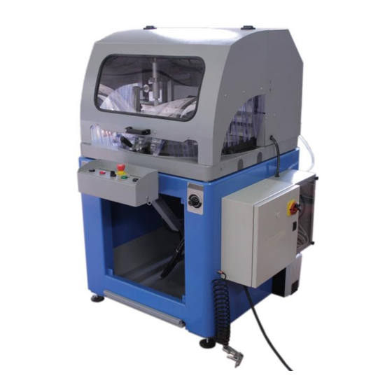
2.CHARACTERISTICS 2.1.M ACHINE DESCRIPTION The machine UNIVER 50 made by PERTICI INDUSTRIES S.r.l. is a single mitre saw and is used to cut-off profiles made of plastic materials, mainly PVC (PoliVinilCloruro), and of light alloys and similar materials. STEEL FRAME... -
Page 9: Technical Data
Widia blades, which have lower noise emission levels than normal blades. NEVER use blades with different dimensions as those specified in this handbook PERTICI INDUSTRIES S.r.l. disclaims each responsibility in case the operator does not respect what the requests of the manufacturer... -
Page 10: Cutting Capacity
ENG Rev 1 SINGLE MITRE SAW 50 page 8 N°1 Widia blade D=500 Z=120 N°2 Vertical pneumatic clamping unit N°2 Horizontal pneumatic clamping unit Lubrication unit Table 4 - Standard set-up 57334 Widia blade D=520 Z=128 57329 Widia blade D=500 Z=120 57701 Vertical pneumatic clamping cylinder 57703... - Page 11 ENG Rev 1 SINGLE MITRE SAW 50 page 9 Figure 3 – Cutting diagram 520 !!!ATTENTION!!! All the operations concering: - set-up, - maintenance, - checking must be done with the machine DISCONNECTED from electricity and pneumatic power supply ATTENTION Any modification not authorized by the manufcturer can modify and/or damage the regular functioning of the machine and anyway void the guarantee on the machine.
-
Page 12: Work Place
ENG Rev 1 SINGLE MITRE SAW 50 page 10 2.2.W ORK PLACE In normal working conditions the operator must stand always outside of the machine (see Error! Reference source not found. and below), in such a position where he/she can see the entire machine and the working table. -
Page 13: Commands Description
Before carrying out any maintenance work, make sure the machine is disconnected from all the power mains (electric and pneumatic) and dissipate the residual power. Please refer to the electrical scheme in attachment with this manual for any information concerning electrical connections Contact PERTICI INDUSTRIES S.r.l. if necessary... -
Page 14: Control Panel
Button nr. 2 – Two hand device electric Figure 7 - Control panel Before carrying out any maintenance work, make sure the machine is disconnected from all the power mains (electric and pneumatic) and dissipate the residual power. Contact PERTICI INDUSTRIES S.r.l. if necessary... -
Page 15: Working Table
Before carrying out any maintenance work, make sure the machine is disconnected from all the power mains (electric and pneumatic) and dissipate the residual power. Contact PERTICI INDUSTRIES S.r.l. if necessary... -
Page 16: Profile Cutting Angle Settings
ENG Rev 1 SINGLE MITRE SAW 50 page 14 2.4.1.P ROFILE CUTTING ANGLE SETTINGS For setting up the desired cutting angle, lift-up the upper safety guard using the handle (point 7 and point 8 in Figure 8) and follow the instructions below: - loosen the handle A - push the button B and rotate the head until you reach the desired cutting angle. -
Page 17: Cutting Unit
ENG Rev 1 SINGLE MITRE SAW 50 page 15 2.5.C UTTING UNIT This assembly consists of a cast iron structure for the transmission between the motor and the blade and a set of mountings for the cylinder that controls the blade outward movement through the rotating working table. - Page 18 500mm (standard machine) NEVER use blades with different dimensions as those specified in this handbook PERTICI INDUSTRIES S.r.l. disclaims each responsibility in case the operator does not respect what the requests of the manufacturer Contact PERTICI INDUSTRIES S.r.l. if necessary...
-
Page 19: Setting The Blade Feeding Speed
ENG Rev 1 SINGLE MITRE SAW 50 page 17 2.5.1.S ETTING THE BLADE FEEDING SPEED The feeding speed of the cutting unit can be regulated depending the material to be cut. To regulate the feeding speed (from 0 up to 0.40 m/sec) use the knob placed on the right side of the machine (RV in Figure 7). - Page 20 ENG Rev 1 SINGLE MITRE SAW 50 page 18 - remove the cover of the transmission belt CP Figure 13 – Setting the belt transmission tension - loosen the screws which locks the electric motor EM on the support - push on the motor EM until the belt reaches the desired tension level - tighten the screws of the electric motor EM - mount again the cover CP and lock it in position using its screws - assemble again the front cover of the steel frame and tighten its locking screws.
-
Page 21: Profile Clamp
Please check that all the clamping units are strongly and firmly locked in position, before using them. Please check that all the clamping units are working correctly, before any working cycle. Contact PERTICI INDUSTRIES S.r.l. if necessary... -
Page 22: Setting The Horizontal Clamping Unit
Please check that all the clamping units are strongly and firmly locked in position, before using them. !!!ATTENZION!!! To get maximum locking strength must press P1 & P2 buttons Contact PERTICI INDUSTRIES S.r.l. if necessary... -
Page 23: Setting The Vertical Clamping Unit
Check always the correct settings of the clamping units by blocking, unblocking and manually forcing he profile before cutting it. Please check that all the clamping units are strongly and firmly locked in position, before using them. Contact PERTICI INDUSTRIES S.r.l. if necessary... -
Page 24: Blade Lubrication Cooling Device
This tank must be filled with a low-fat lubricating liquid solution: loosen the tap (T), fill the tank (S) and tighten again the tap (T). We strongly suggest to use Liquid Lubrificating PERTICI that beyond to be not obnoxious has functional and chemical-physics characteristics properly created for the requested lubrication and besides it is ecologically guaranteed. - Page 25 (electric and pneumatic) and dissipate the residual power. Lubricants and oils are highly polluting substances: to dispose them call an authorised specialised firm according with the relevant rules of the Country where the machine is installed.. Contact PERTICI INDUSTRIES S.r.l. if necessary...
-
Page 26: Safety Protection Devices
Always check that guards of the cutting unit and plastic barriers are in good state. if damaged or worn, it is necessary to replace them suddenly. always check that the safety switch is in good state. If damaged or worn, It is necessary to replace it suddenly. Contact PERTICI INDUSTRIES S.r.l. if necessary... -
Page 27: Limits Of Use
2.9.1.R ECOMENDED USE The UNIVER 50 single mitre saw can be used inside industrial environment only for cutting plastic made profiles, mainly PVC and assimilable materials, and light alloy made profiles. To use the machine for CUTTING LIGHT ALLOY MADE PROFILES, it is mandatory LUBRICATE blades using the lubrication system. -
Page 28: Not Recommended Use And Warnings
2.10.C ONFORMITY TO SAFETY STANDARDS The UNIVER 50 machine has been designed and built in conformity of the following standards: 2006/42/ CEE (Directive on Machines) 2006/95/CEE (Directive on Low Voltage) 2004/108/CEE (Directive on Electromagnetic Compatibility). -
Page 29: Safety
- Safe use of the machine is guaranteed only for functions and materials described in this handbook. PERTICI INDUSTRIES S.r.l. declines any responsibility if the machine is used for not indicated scopes and not in conformity to these instructions for use PERTICI INDUSTRIES S.r.l. -
Page 30: Safe Working Operations
ENG Rev 1 SINGLE MITRE SAW 50 page 28 Before carrying out any maintenance work, make sure the machine is disconnected from all the power mains (electric and pneumatic) and dissipate the residual power, unless there are different indications. The operator must read the operation manual very carefully, before using this machine. The use of the following personal protections is also suggested for the operator: - goggles (always - for protection against dust, shavings and residues in general);... -
Page 31: Information On Residual Risks
ENG Rev 1 SINGLE MITRE SAW 50 page 29 - know perfectly all the factors influencing the exposition to dust, for example: type of the material to be cut; importance of dust extraction; correct setting of dust extraction devices; that the dust extraction plant has to be turned on before start working. It is important that: - the floor of the area around the machine has to be plain, clean and neat;... -
Page 32: Residual Risks Related To The Worked Material
(cutting tools) and throwing of machining parts (pieces, tools, chips, etc.). Check periodically the integrity of these protection devices and perform all needed maintenance operations so the machine is always in good and safe state. Contact PERTICI INDUSTRIES S.r.l. if necessary... -
Page 33: Risk Due To Noise Emission Levels
ENG Rev 1 SINGLE MITRE SAW 50 page 31 3.7. R ISK DUE TO NOISE EMISSION LEVELS The test conditions and results are given in the addendum ANNEX 5. The operator is advised to use protective equipment, such as good quality soundproof earphones. -
Page 34: Plates
ENG Rev 1 SINGLE MITRE SAW 50 page 32 3.10. P LATES The following is the data plate, which is positioned on the machine. Figure 22 –CE data plate Always check that figures, colours, words of the safety signs are in good state. If damaged or worn, It is necessary to replace them suddenly and call the responsible of the manufacturing plant of your firm. -
Page 35: Installation
Follow all possible precautions during moving and transporting operations; avoid damages and dangers to persons, machine and things. UNIVER 50 machines for condensation drainage are delivered fully greased and wrapped in heat-shrink nylon. The robust form and design of the machine guarantee that it can be transported and stored safely and without damage. -
Page 36: Storage
THERE IS THIS SYMBOL Figure 23 – Lifting with forcklift device Before moving the machine check that the load is well balanced Contact PERTICI INDUSTRIES S.r.l. if necessary 4.2. S TORAGE When the machine has to be stored and kept idle for a long time, the following measures have to be taken: - store the machine in a closed place;... -
Page 37: Prearrangements
Check that in the entire area where the machine is placed there is enough and correct lightning The areas all around the mahine must have free rooms for passage so there are not risks and/or danger for the operator and the material to be worked. Contact PERTICI INDUSTRIES S.r.l. if necessary... -
Page 38: Installation
ENG Rev 1 SINGLE MITRE SAW 50 page 36 4.5.I NSTALLATION 4.5.1.A LIGNMENT This operation is very important to obtain the same sharp and repetitive cut as the one reached during internal test. Put the positioniong feet (see Figure 24) in the relevant holes in the lower corners of the machine. -
Page 39: Pneumatic Air Connection
SINGLE MITRE SAW 50 page 37 Assemblying and levelling is performed by personnel of PERTICI INDUSTRIES S.r.l. or personnel authorised by PERTICI INDUSTRIES S.r.l.. Contact PERTICI INDUSTRIES S.r.l. if the machine will be installed in other places in the future... - Page 40 Non Do not modify or tamper with the pneumatic circuit Do not perform any setting/regulation without previous written authorization by PERTICI INDUSTRIES S.r.l. or personnel authorized by PERTICI INDUSTRIES S.r.l. Connect the pipe from the pneumatic power plant to the slide valve mounted on the FRL air treatment unit.
-
Page 41: Electric Connection
PERTICI INDUSTRIES S.r.l. or personnel authorized by PERTICI INDUSTRIES S.r.l. Contact PERTICI INDUSTRIES S.r.l. if in future the machine will be installed in other places Do not connect the machine to the main electric power supply until it is not completely assembled and placed. - Page 42 ENG Rev 1 SINGLE MITRE SAW 50 page 40 Check that the cable which connect the machine to the electric power supply is in good state and correctly positioned. The user's electric power supply plant must conform to current electricity standard of the Country where the machine is installed.
-
Page 43: Check The Correct Sense Of Rotation Of The Blade
ENG Rev 1 SINGLE MITRE SAW 50 page 41 Contact PERTICI INDUSTRIES S.r.l. if necessary 4.8.C HECK THE CORRECT SENSE OF ROTATION OF THE BLADE To check that the electric connection has been done correcty, and then that the blade turns towards the correct direction, plese follow the instruction below: A. -
Page 44: Connection To Shaving Suction System
Do not tamper with the electricl circuit Do not modify any connection inside the electric cabinet Contact PERTICI INDUSTRIES S.r.l. if necessary 4.9.C ONNECTION TO SHAVING SUCTION SYSTEM The machine has in its rear upper part a hood which can be connected to the external shaving suction system. -
Page 45: Use
The presence of water on/inside the profiles could generte damages and/or corrosion to mobiland fixed parts of the machine PERTICI INDUSTRIES S.r.l. does not give guarantee if the machine is used in these conditions. during previous working cycles PARTS OF PROFILE BAR got stuck in some mechanical parts of the machine, visible from the front transparent window panel. -
Page 46: Warnings To Guarantee Safety During Use
ENG Rev 1 SINGLE MITRE SAW 50 page 44 5.2.W ARNINGS TO GUARANTEE SAFETY DURING USE !!!ATTENTION!!! During any operation be sure that no person other than the operator is inside the dangerous area of the machine Do not remove for any reasons the safety guards and protection safety covers Do not remove or tamper with the safety guards Do not tamper with the safety protection devices Check periodically the integrity of the safety guards of the cutting area and... -
Page 47: Functional Cycle
ENG Rev 1 SINGLE MITRE SAW 50 page 45 Take maximum care when the cutting unit is working - Never leave cut workpieces on the working table; remove them immediately after the machining to avoid having pieces of section bar lying around on the working table The minimum amount cut off in bar offcut operations = not less than 50 mm 5.3.F UNCTIONAL CYCLE... - Page 48 ENG Rev 1 SINGLE MITRE SAW 50 page 46 Check that the air pressure value, as indicated in the manometer, is about 8 (bar/atm) when the machine is not working 3. TURN THE MAIN POWER SWITCH in the electric cabinet to POSITION I (ON) Figure 33 –...
- Page 49 ENG Rev 1 SINGLE MITRE SAW 50 page 47 The CLAMPING CYLINDERS WORK WITH DOUBLE PRESSURE VALUES: a lower value for first positioning, an higher value for definitive blocking. 6. MOVE DOWN the upper safety cover Figure 36 – Close the upper safety cover 7.
-
Page 50: Emergency Devices
48 9. UNBLOCK THE PROFILE BAR turning the selector SBS counterclockwise Figure 38 – Profile bar unblocking Contact PERTICI INDUSTRIES S.r.l. if necessary 5.4.E MERGENCY DEVICES Push the emergency red button PE1 (see Figure 39) at any time to stop any movement of the machine Figure 39 –... - Page 51 Be sure to operate fully in safe mode To TURN ON THE MACHINE AGAIN, pull-up the emergency red button PE1; at the same time the red light LE will stop lightning. Contact PERTICI INDUSTRIES S.r.l. if necessary...
-
Page 52: Maintenance
DO NOT DISCONNECT the machine from the compressed air power circuit is this is not requested The UNIVER 50 mitre single saws do not require any special maintenance operations. The technical design, materials used and protective paints have been specially developed and selected to reduce maintenance work. -
Page 53: Routine Maintenance ( Daily )
Check the liquid level: if necessary add lubricant Tank of lubrication liquid for blade " Alcut Plus " made by PERTICI INDUSTRIES S.r.l. Table 8 - Routine maintenance plan EVERY DAY AT THE END OF WORK - lock the main switch of electric power - disconnect the pneumatic air power supply 6.2. -
Page 54: Replacing Blade
The new blade must be of good quality NEVER use blades with different dimensions as those specified in this handbook PERTICI INDUSTRIES S.r.l. disclaims each responsibility in case the operator does not respect what the requests of the manufacturer ATTENTION The blade has not a brake: its stop is NOT immediate but it needs some time for a complete stop. - Page 55 ENG Rev 1 SINGLE MITRE SAW 50 page 53 REPLACING BLADE: Disconnect the machine from electric power supply. A1. Remove front safety cover. Figure 41 – Remove front safety cover to have acess to blade A2. Block the end part of the shaft using key number 19, use key number 45 to loosen the screw 1.
- Page 56 B3. Check that the blade is of good quality. B4. Check that the blade is correctly mounted. ATTENTION!!!!!! ALWAYS re-assemble the safety protection covers and tighten their screws bfore turning on again the machine Contact PERTICI INDUSTRIES S.r.l. if necessary...
-
Page 57: Spare Parts
ENG Rev 1 SINGLE MITRE SAW 50 page 55 Figure 44 – Re-assemblethe front safety cover 6.4.S PARE PARTS To classify and identify the different components to be considered as spare parts refer to all technical tables enclosed in this manual and to the respective lists. - Page 58 ENG Rev 1 SINGLE MITRE SAW 50 page 56...
-
Page 59: Annex 1
ENG Rev 1 SINGLE MITRE SAW 50 page 57 ANNEX 1 COMMERCIAL COMPONENTS... - Page 60 ENG Rev 1 SINGLE MITRE SAW 50 page 58 DRAWING OF COAXIAL UNIT...
- Page 61 ENG Rev 1 SINGLE MITRE SAW 50 page 59 LEGENDA OF DEPICTED PARTS: DESCRIZIONE CODICE OR 2025 OR 4093 OR 115 OR 3225 OR 3112 OR 3125 GUARNIZIONE 1501 - 0400 GASKET JOINT JUNTA DICTUNG USZCZELKA ASR 5735 B3 1212 P5008 DEM63 DI 050 GUIDA...
-
Page 62: Annex 2
ENG Rev 1 SINGLE MITRE SAW 50 page 60... - Page 63 ENG Rev 1 SINGLE MITRE SAW 50 page 61 ANNEX 2 EXPLODED DRAWING OF MECHANICAL PARTS...
- Page 64 ENG Rev 1 SINGLE MITRE SAW 50 page 62 DRAWINGS AND LISTS ARE TO BE UPDATED...
-
Page 65: Annex 3
(C 2) and the place taken by the wire inside the connectors (12) LIST OF ELECTRICAL COMPONENTS THE LIST OF COMPONENTS IS BROKEN DOWN AS FOLLOWS: RIF. (REFERENCE) (PAGE) DESCRIZIONE (DESCRIPTION OF MATERIAL) NUM. (NUMBER OF ITEMS) TIPO (MATERIAL TYPE OR MANUFACTURER CODE) FORNITORE (PRODUCER OF MATERIAL) NS.CODICE (PERTICI CODE) - Page 66 ENG Rev 1 SINGLE MITRE SAW 50 page 64 RIF. This column contains the components references used in the wiring diagram, in alphnumerical order (eg. C1, F2). If the component consists of several parts, the reference will be given on the corresponding number of lines, describing the single part of the component on each of the lines.
-
Page 67: Annex 4
ENG Rev 1 SINGLE MITRE SAW 50 page 65 ANNEX 4 PNEUMATIC CIRCUIT INDEX................FUNCTIONAL DIAGRAM……….…………...……………. Drawing... - Page 68 ENG Rev 1 SINGLE MITRE SAW 50 page 66 FUNCTIONAL LAY-OUY On each page, the coordinates of a symbol can be found with the horizontal letters vertical number...
-
Page 69: Annex 5
ENG Rev 1 SINGLE MITRE SAW 50 page 67 ANNEX 5 NOISE TESTS The results of the measurements made are given in the following tables: ACOUSTIC RADIATION PRESSURE LEVEL LpAm dB(A): 95,7 ACOUSTIC POWER LEVEL dB(A): 111,8 ACOUSTIC PRESSURE LEVEL IN OPERATOR'S POSITION dB(A): 94.3 The test conditions and instruments used are described in the TECHNICAL BOOKLET corresponding to this manual.
Need help?
Do you have a question about the Univer 50 and is the answer not in the manual?
Questions and answers
Blade turns but won't lift
The blade on the Pertici Univer 50 may not lift due to several possible reasons:
1. Power Issue – Ensure the machine is connected to the correct electric and pneumatic power sources. Any disconnection may prevent the blade from lifting.
2. Residual Energy – If there is any residual energy in the system, it should be fully dissipated before operation.
3. Hydraulic-Pneumatic Cylinder – The blade movement is powered by a hydraulic-pneumatic cylinder. If there is an issue with air or hydraulic pressure, the blade may not lift.
4. Control Device Malfunction – The machine uses a two-handed control device (buttons SB1 and SB2) to operate the blade. If the controls are not functioning properly, the blade may not respond.
5. Mechanical Obstruction – Check for any physical blockage or mechanical issue preventing movement within the cutting unit.
6. Incorrect Phase Connection – If the electric motor is not functioning correctly due to incorrect phase wiring, the blade movement may be affected.
To resolve the issue, verify power connections, check the hydraulic-pneumatic system, ensure the control buttons function properly, and inspect for mechanical obstructions.
This answer is automatically generated
manca lo schema elettrico del tipo “univer 50”
The electrical diagram for the Pertici Univer 50 is included as an attachment with the manual.
This answer is automatically generated